EP1157944A2 - Can for one or two-components products with dispensing tube - Google Patents
Can for one or two-components products with dispensing tube Download PDFInfo
- Publication number
- EP1157944A2 EP1157944A2 EP01112455A EP01112455A EP1157944A2 EP 1157944 A2 EP1157944 A2 EP 1157944A2 EP 01112455 A EP01112455 A EP 01112455A EP 01112455 A EP01112455 A EP 01112455A EP 1157944 A2 EP1157944 A2 EP 1157944A2
- Authority
- EP
- European Patent Office
- Prior art keywords
- dispensing
- dispensing spout
- spout
- component
- particular according
- Prior art date
- Legal status (The legal status is an assumption and is not a legal conclusion. Google has not performed a legal analysis and makes no representation as to the accuracy of the status listed.)
- Granted
Links
Images


Classifications
-
- B—PERFORMING OPERATIONS; TRANSPORTING
- B65—CONVEYING; PACKING; STORING; HANDLING THIN OR FILAMENTARY MATERIAL
- B65D—CONTAINERS FOR STORAGE OR TRANSPORT OF ARTICLES OR MATERIALS, e.g. BAGS, BARRELS, BOTTLES, BOXES, CANS, CARTONS, CRATES, DRUMS, JARS, TANKS, HOPPERS, FORWARDING CONTAINERS; ACCESSORIES, CLOSURES, OR FITTINGS THEREFOR; PACKAGING ELEMENTS; PACKAGES
- B65D83/00—Containers or packages with special means for dispensing contents
- B65D83/14—Containers or packages with special means for dispensing contents for delivery of liquid or semi-liquid contents by internal gaseous pressure, i.e. aerosol containers comprising propellant for a product delivered by a propellant
- B65D83/28—Nozzles, nozzle fittings or accessories specially adapted therefor
- B65D83/30—Nozzles, nozzle fittings or accessories specially adapted therefor for guiding the flow of spray, e.g. funnels, hoods
- B65D83/303—Nozzles, nozzle fittings or accessories specially adapted therefor for guiding the flow of spray, e.g. funnels, hoods using extension tubes located in or at the outlet duct of the nozzle assembly
-
- B—PERFORMING OPERATIONS; TRANSPORTING
- B65—CONVEYING; PACKING; STORING; HANDLING THIN OR FILAMENTARY MATERIAL
- B65D—CONTAINERS FOR STORAGE OR TRANSPORT OF ARTICLES OR MATERIALS, e.g. BAGS, BARRELS, BOTTLES, BOXES, CANS, CARTONS, CRATES, DRUMS, JARS, TANKS, HOPPERS, FORWARDING CONTAINERS; ACCESSORIES, CLOSURES, OR FITTINGS THEREFOR; PACKAGING ELEMENTS; PACKAGES
- B65D83/00—Containers or packages with special means for dispensing contents
- B65D83/14—Containers or packages with special means for dispensing contents for delivery of liquid or semi-liquid contents by internal gaseous pressure, i.e. aerosol containers comprising propellant for a product delivered by a propellant
- B65D83/68—Dispensing two or more contents, e.g. sequential dispensing or simultaneous dispensing of two or more products without mixing them
- B65D83/682—Dispensing two or more contents, e.g. sequential dispensing or simultaneous dispensing of two or more products without mixing them the products being first separated, but finally mixed, e.g. in a dispensing head
Definitions
- the invention initially relates to a two-component can for the introduction of foam in the construction area an dispensing spout having an opening.
- the latter can go through Do not drain from resting on the dispensing spout.
- An introduction of further support means, such as a kinked cardboard strip is not necessary.
- the local foam can be introduced specifically.
- Even with one Foaming, for example, horizontal joints results themselves by designing the Output nozzle the beneficial effect that by a for laterally extending the dispensing spout Output the local foam a targeted, for example punctiform adhesion of the same between the parts of the building can be achieved. So about that also by means of the dispensing spout designed according to the invention a door frame or a window frame for the first Fixation at points using two-component foam be fixed without the risk of the Foam drips off in the course of the introduction.
- the exit direction a blunt with the longitudinal extension of the dispensing spout Angle, for example an angle of 95 ° to 160 ° is preferred Includes 135 °.
- the exit direction with the longitudinal extent encloses a right angle. So with one horizontal alignment of the dispensing spout for backfilling a vertical joint preferred the dispensing opening aligned vertically upwards.
- the donation opening to both sides, d. H. two opposite Openings are formed, which is particularly the case with an introduction of foam in horizontal joints as proves advantageous.
- the donation opening can be done here through a the spout jacket in a right Aligned to the longitudinal extent of the dispensing spout Opening to be formed, this when closed End face of the free, the two-component can opposite end of the dispensing spout.
- that the donation opening sideways by less than that Measure a diameter of the dispensing spout over it protrudes.
- the measure with which the donation opening laterally over the dispensing spout protrudes for example, a third of the Correspond to the nozzle diameter. It is also an advantage if the donation opening area of the cross-sectional area of the outlet spout passage area.
- the donation opening with the outer surface of the dispensing spout So can also use a 90 ° elbow at the end of the dispensing spout be provided, the perpendicular to the spout longitudinal extension aligned donation opening with closes an apex of the dispensing spout wall.
- the donation opening within the contour of the uninfluenced Outside surface of the dispensing spout is formed.
- the V-neck is chosen so that it is starting from the nozzle wall up to approximately the longitudinal axis of the nozzle extends, further the V-legs one Include angles from 60 ° to 120 °, preferably 90 °. Regardless of the design and number of Donation openings are generally closed Upstream end of the dispensing spout.
- the dispensing spout is elongated is, the length of the dispensing spout being more than that Is five times the diameter of the dispensing spout. So is for example with an outer diameter of 8 mm given an inner diameter of 6 mm, the spout length is, for example, 250 mm.
- the donation opening the dispensing spout can be circular in the usual way his. Alternatively, however, there is also training with an oval opening.
- the dispensing spout according to the invention can have a length, which allows them to be placed directly on the can. However, training is also conceivable, in which the dispensing spout is formed from the insertion part, to arrange them to a usual straight line Dispensing tubes.
- the dispensing spout be a tapered one Neck area with one for plug securing External ribbing.
- the tapered neck area in the longitudinal direction tapers conically.
- the invention relates to a one-component can for the introduction of grout in the construction area with a dispensing spout having a dispensing opening.
- Such one-component cans are in shape, for example of cartridges for the insertion of silicone or acrylic known.
- the invention suggests improvement the manageability the design of the dispensing spout according to the features of one or more of claims 1 to 9 before.
- the invention further relates to a donation opening dispensing spout for an input or Multi-component box for introducing local foam into the Construction area.
- spouts are known and have an elongated, tubular shape, with opposing openings.
- the exit direction relative to a longitudinal extension of the dispensing spout is angled.
- the local foam can be introduced in a targeted manner.
- the dispensing spout forms, especially at foaming of vertical joints through the angled Exit direction a support element within the Fugue, which drains the inserted local foam counteracts.
- the exit direction with the longitudinal extension a right one Includes angle.
- foaming vertical joints preferably detects the donation opening above.
- the end of the dispensing spout over a 90 ° elbow into the donation opening transforms.
- the donation opening laterally by less than the measure of one Diameter protrudes beyond this.
- the donation opening within the contour the uninfluenced outer surface of the dispensing spout with the dispensing opening preferably being V-shaped is incised.
- the invention further proposes that the Output spout is elongated, the Length of the spout more than five times the diameter the dispensing spout is.
- the donation opening of the Output spout can be circular in the usual way his. Alternatively, however, there is also training with an oval opening.
- the dispensing spout according to the invention can have a length, which allows them to be placed directly on the can. However, training is also conceivable, in which the dispensing spout is formed from the insertion part, to arrange them to a usual straight line Dispensing tubes.
- the dispensing spout be a tapered one Neck area with one for plug securing External ribbing.
- the tapered neck area in the longitudinal direction tapers conically.
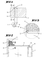
- FIG. 1 shows a two-component box 1 with one, one Dispensing opening 2 having tubular dispensing spout 3 for the introduction of foam 4 in the construction area. Shown is the introduction of the local foam 4 in a Vertical joint 5 between a door frame and a subsequent one Masonry 7.
- the dispensing spout 3 shown in FIGS. 1 to 3 first embodiment is below based on the Individual representations in FIGS. 4 to 6 explained in more detail.
- the dispensing spout 3 is elongated, wherein the length 1 of the dispensing nozzle 3 more than five times of the diameter d of the dispensing nozzle 3. So is a diameter d of approx. 8 mm is provided for a Length 1 from 200 to 300 mm, for example 250 mm.
- the Inner diameter d ' is in the illustrated embodiment approx. 6 mm.
- the dispensing nozzle 3 merges into a 90 ° elbow 11, which is another, straight Spout section 12 connects.
- the dispensing opening is 2 positioned such that the exit direction r of the Local foam with the longitudinal extension of the dispensing spout 3 encloses a right angle.
- the one at the free end of the spout section 12 formed dispensing opening 2 protrudes laterally by a dimension a beyond the dispensing spout 3, this dimension a is smaller than the diameter d the output spout 3.
- a protrusion measure a of approx. 2 to 3 mm.
- Due to the 90 ° bend of the dispensing opening according to the invention 2 acts to the longitudinal extent of the dispensing spout 3 the dispensing spout 3 in particular when it is introduced of foam 4 in a vertical joint 5 as a inserted local foam 4 supporting, a drain same preventing element (see. Fig. 3).
- An alternative embodiment of the dispensing spout is 7 and 8, in which is equal to The embodiment described above has the free end 10 the dispensing nozzle 3 merges into a 90 ° elbow 11.
- the donation opening 2 is immediately in the Area of the free arch end formed so that this with the outer surface of the dispensing nozzle 3 in the opening plane at the apex line of the dispensing spout wall completes.
- the dispensing spout 3 can also have a dispensing opening 2, which are provided within the contour the uninfluenced outer surface of the dispensing spout 3 is trained.
- the donation opening 2 is this closed end 13 of the outlet nozzle 3 upstream and formed by a V-shaped incision.
- the V-shaped incision is chosen so that the V-leg about an angle of 90 ° include, with a valley line 14 the dispensing spout 3 about in the area of the body's longitudinal axis.
- the exit direction is also in this embodiment r of the local foam relative to the longitudinal extent the dispensing spout 3 angled by approximately 90 °.
- Output spout 3 is a fourth embodiment of an inventive one Output spout 3 shown, in which two opposite, one on the right Including angle to the longitudinal extent of the dispensing nozzle 3 Donation openings 2 are provided.
- Such Output spouts 3 can advantageously be used for Introduction of foam 4 in horizontal, for example Serve joints.
- the embodiment is the dispensing spout 3 as a plug-in part for placement on a standard, straight-line dispensing tube educated.
- the output nozzle 3 has this Execution from a tapered, preferably to the Internal cross-section of a straight-line dispensing tube adapted neck area 20, which in addition for locking with a screw-shaped External ribbing 21 is provided.
- the Output spout 3 in this version ends in a cranked section 22 at its free end the dispensing opening 2 is formed.
- the latter is here so that it is aligned with the outer surface of the Dispensing nozzle 3 in terms of opening level at the level of a vertex line the larger diameter spout wall completes.
- the exit direction closes accordingly r with the longitudinal extension of the dispensing nozzle 3 obtuse angle alpha, in the embodiment shown Is 135 °.
- the donation opening is oval 2.
- the tapered neck region 20 extends in the longitudinal direction be conically tapered.
- the illustrated embodiments of the dispensing spout 3 are in the same way, joint material such as.
Abstract
Description
Die Erfindung betrifft zunächst eine Zwei-Komponenten-Dose zur Einbringung von Ortschaum im Baubereich mit einer, eine Spendeöffnung aufweisenden Ausgabetülle.The invention initially relates to a two-component can for the introduction of foam in the construction area an dispensing spout having an opening.
Bei einem Einbringen von Bauschaum, insbesondere Zwei-Komponenten-Schaum, in einen Spalt, beispielsweise zwischen einer Türzarge oder einem Fensterrahmen und dem anschließenden Mauerwerk, ergibt sich in der Praxis die Problematik, dass der Bauschaum abtropft und nicht zugleich an der Stelle haften bleibt, an der dieser eingebracht werden soll. Um diesem Tropfen entgegen zu wirken, ist es bekannt, einen gefalteten Pappstreifen oder dergleichen in die Fugen einzustecken und hiernach den Schaum oberhalb diese Pappstreifens einzudüsen. Durch den nach oben ragenden Falz des Pappstreifen verteilt sich hiernach der Schaum einerseits gegen den Fensterrahmen oder dergleichen und andererseits gegen das Mauerwerk. Nach einem Aushärten des Schaumes wird der überstehende Abschnitt des Pappstreifens zusammen mit dem ausgequollenen und erhärteten Schaum abgeschnitten.When building foam, in particular two-component foam, is introduced, in a gap, for example between a door frame or a window frame and the subsequent masonry results in practice the problem that the building foam drips and not at the same time sticks to where it is should be introduced. To counter this drop act, it is known a folded cardboard strip or the like in the joints and after that inject the foam above this cardboard strip. Due to the upward fold of the cardboard strip The foam is then distributed against the one hand Window frames or the like and on the other hand against the masonry. After the foam has hardened the protruding section of the cardboard strip together cut off with the swollen and hardened foam.
Im Hinblick auf den zuvor beschriebenen Stand der Technik wird eine technische Problematik der Erfindung dahin gesehen, eine Zwei-Komponenten-Dose zur Einbringung von Ortschaum insbesondere hinsichtlich einer vereinfachten Handhabung zu verbessern.In view of the prior art described above becomes a technical problem of the invention seen there, a two-component box for insertion of foam in particular with regard to one to improve simplified handling.
Diese Problematik ist zunächst und im Wesentlichen durch den Gegenstand des Anspruches 1 gelöst, wobei darauf abgestellt ist, dass die Austrittsrichtung relativ zu einer Längserstreckung der Ausgabetülle abgewinkelt ist. Im Gegensatz zum bekannten Stand der Technik, bei welchem die Austrittsrichtung des Ortschaumes in Längserstreckung der in der Regel röhrchenartigen Ausgabetülle verläuft, erfolgt erfindungsgemäß die Ausgabe des Ortschaumes in einem Winkel zur Tüllenlängserstreckung, so dass bei einem üblichen waagerechten Einführen der Ausgabetülle in die auszuschäumende Fuge der ausgedüste Schaum in die gewünschte Richtung verbracht wird. Hierbei erfüllt die Ausgabetülle bei einer nach oben abgewinkelten Austrittsrichtung insbesondere bei einem Ausschäumen von Vertikalfugen die Aufgabe einer Stützung des eingebrachten Schaumes. Letzter kann durch Aufliegen auf der Ausgabetülle nicht mehr abtropfen. Ein Einführen weiterer Abstützmittel, wie beispielsweise einen abgeknickten Pappstreifen, ist nicht erforderlich. Zufolge dieser erfindungsgemäßen Ausgestaltung ist der Ortschaum gezielt einbringbar. Auch bei einem Ausschäumen von beispielsweise waagerechten Fugen ergibt sich durch erfindungsgemäße Ausgestaltung der Ausgabetülle der vorteilhafte Effekt, dass durch ein zur Längserstreckung der Ausgabetülle seitlich ausgerichtetes Ausgeben des Ortschaumes eine gezielte, beispielsweise punktförmige Anhaftung desselben zwischen den Bauwerksteilen erzielt werden kann. So kann darüber hinaus mittels der erfindungsgemäß ausgebildeten Ausgabetülle eine Türzarge oder ein Fensterrahmen zur ersten Fixierung punktweise mittels Zwei-Komponenten-Schaum fixiert werden, ohne dass die Gefahr entsteht, dass der Schaum im Zuge des Einbringens abtropft. Diesbezüglich wird weiter vorgeschlagen, dass die Austrittsrichtung mit der Längserstreckung der Ausgabetülle einen stumpfen Winkel, bspw. einen Winkel von 95° bis 160° bevorzugt 135° einschließt. In einer vorteilhaften Weiterentwicklung des Erfindungsgegenstandes ist vorgesehen, dass die Austrittsrichtung mit der Längserstreckung einen rechten Winkel einschließt. Demnach ist bei einer waagerechten Ausrichtung der Ausgabetülle zur Verfüllung einer Vertikalfuge die Spendeöffnung bevorzugt senkrecht nach oben weisend ausgerichtet. Darüber hinaus ist es auch denkbar, dass zugleich die Spendeöffnung zu beiden Seiten hin, d. h. zwei gegenüberliegende Öffnungen ausgebildet sind, was sich insbesondere bei einem Einbringen von Ortschaum in Horizontalfugen als vorteilhaft erweist. Die Spendeöffnung kann hierbei durch eine den Ausgabetüllenmantel in einem rechten Winkel zur Längserstreckung der Ausgabetülle ausgerichteten Durchbrechung ausgebildet sein, dies bei geschlossener Stirnfläche des freien, der Zwei-Komponenten-Dose abgewandten Endes der Ausgabetülle. Bevorzugt wird eine Ausgestaltung, bei welcher das Ende der Ausgabetülle über ein 90°-Bogenstück in die Spendeöffnung übergeht. Zudem ist in einer beispielhaften Ausgestaltung vorgesehen, dass die Spendeöffnung seitlich um weniger als das Maß eines Durchmessers der Ausgabetülle über diese hinausragt. Bevorzugt schließt sich an das endseitige 90°-Bogenstück ein gerades Tüllenstück an. Das Maß mit welchem die Spendeöffnung seitlich über die Ausgabetülle hinausragt kann beispielsweise einem Drittel des Tüllendurchmessers entsprechen. Von Vorteil ist auch, wenn die Spendeöffnungsfläche der Querschnittsfläche des Ausgabetüllen-Durchtrittsbereiches entspricht. In einer alternativen Ausgestaltung des Erfindungsgegenstandes kann vorgesehen sein, dass die Spendeöffnung mit der Außenfläche der Ausgabetülle abschließt. So kann auch hier ein 90°-Bogenstück am Ende der Ausgabetülle vorgesehen sein, deren senkrecht zur Ausgabentüllen-Längserstreckung ausgerichtete Spendeöffnung mit einem Scheitelpunkt der Ausgabetüllenwandung abschließt. Des weiteren kann alternativ vorgesehen sein, dass die Spendeöffnung innerhalb der Kontur der unbeeinflussten Außenfläche der Ausgabetülle ausgebildet ist. So beispielsweise, wie bereits erwähnt, in Form einer die Tüllenwandung durchsetzenden Durchbrechung. Diese kann in weiterer Ausführung V-förmig eingeschnitten sein, zur Bildung einer orgelpfeifenähnlichen Öffnung, wobei der V-Ausschnitt so gewählt ist, dass sich dieser von der Tüllenwandung ausgehend bis etwa zur Tüllenlängsachse erstreckt, wobei weiter die V-Schenkel einen Winkel von 60° bis 120° bevorzugt 90° einschließen. Unabhängig von der Ausgestaltung und auch Anzahl der Spendeöffnungen sind diese generell dem geschlossenen Ende der Ausgabetülle vorgelagert. Auch wird vorgeschlagen, dass die Ausgabetülle langgestreckt ausgebildet ist, wobei die Länge der Ausgabetülle mehr als das Fünffache des Durchmesser der Ausgabetülle beträgt. So ist beispielsweise bei einem Außendurchmesser von 8 mm ein Innendurchmesser von 6 mm gegeben, wobei die Tüllenlänge beispielsweise 250 mm beträgt. Die Spendeöffnung der Ausgabetülle kann in üblicher Weise kreisrund ausgebildet sein. Alternativ besteht jedoch auch eine Ausbildung mit einer ein Oval bildenden Spendeöffnung. Die erfindungsgemäße Ausgabetülle kann eine Länge aufweisen, die es erlaubt, diese direkt an der Dose anzuordnen. Denkbar ist jedoch auch eine Ausbildung, bei welcher die Ausgabetülle ab Einsteckteil ausgebildet ist, zur Anordnung derselben an ein übliches geradliniges Ausgaberöhrchen. Um hier eine handhabungseinfache und zugleich sichere Verbindung zu gewährleisten, wird vorgeschlagen, dass die Ausgabetülle einen verjüngten Halsbereich aufweist mit einer zur Stecksicherung dienenden Außenverrippung. Schließlich ist diesbezüglich vorgesehen, dass der verjüngte Halsbereich in Längsrichtung sich konisch verjüngt. This problem is first and foremost solved by the subject matter of claim 1, wherein is based on the fact that the exit direction is relative angled to a longitudinal extent of the dispensing spout is. In contrast to the known state of the art, in which the exit direction of the local foam in Longitudinal extension of the generally tubular delivery spout runs, the output takes place according to the invention of the local foam at an angle to the longitudinal extension of the spout, so that with a normal horizontal insertion the dispensing nozzle in the joint to be foamed out Foam spent in the desired direction becomes. Here, the output nozzle meets one after exit direction angled above, especially at foaming vertical joints is the task of a Support of the introduced foam. The latter can go through Do not drain from resting on the dispensing spout. An introduction of further support means, such as a kinked cardboard strip is not necessary. As a result of this configuration according to the invention the local foam can be introduced specifically. Even with one Foaming, for example, horizontal joints results themselves by designing the Output nozzle the beneficial effect that by a for laterally extending the dispensing spout Output the local foam a targeted, for example punctiform adhesion of the same between the parts of the building can be achieved. So about that also by means of the dispensing spout designed according to the invention a door frame or a window frame for the first Fixation at points using two-component foam be fixed without the risk of the Foam drips off in the course of the introduction. In this regard it is further suggested that the exit direction a blunt with the longitudinal extension of the dispensing spout Angle, for example an angle of 95 ° to 160 ° is preferred Includes 135 °. In an advantageous further development the subject of the invention is provided that the exit direction with the longitudinal extent encloses a right angle. So with one horizontal alignment of the dispensing spout for backfilling a vertical joint preferred the dispensing opening aligned vertically upwards. Furthermore it is also conceivable that at the same time the donation opening to both sides, d. H. two opposite Openings are formed, which is particularly the case with an introduction of foam in horizontal joints as proves advantageous. The donation opening can be done here through a the spout jacket in a right Aligned to the longitudinal extent of the dispensing spout Opening to be formed, this when closed End face of the free, the two-component can opposite end of the dispensing spout. One is preferred Design in which the end of the dispensing spout passes through a 90 ° elbow into the donation opening. In addition, in an exemplary embodiment, that the donation opening sideways by less than that Measure a diameter of the dispensing spout over it protrudes. Preferably adjoins the end 90 ° elbow to a straight grommet. The measure with which the donation opening laterally over the dispensing spout protrudes, for example, a third of the Correspond to the nozzle diameter. It is also an advantage if the donation opening area of the cross-sectional area of the outlet spout passage area. In an alternative embodiment of the subject matter of the invention can be provided that the donation opening with the outer surface of the dispensing spout. So can also use a 90 ° elbow at the end of the dispensing spout be provided, the perpendicular to the spout longitudinal extension aligned donation opening with closes an apex of the dispensing spout wall. Furthermore, it can alternatively be provided that the donation opening within the contour of the uninfluenced Outside surface of the dispensing spout is formed. For example, as already mentioned, in the form of a breakthrough penetrating the sleeve wall. This can be cut into a V-shape in another version to form an organ pipe-like opening, the V-neck is chosen so that it is starting from the nozzle wall up to approximately the longitudinal axis of the nozzle extends, further the V-legs one Include angles from 60 ° to 120 °, preferably 90 °. Regardless of the design and number of Donation openings are generally closed Upstream end of the dispensing spout. It is also suggested that the dispensing spout is elongated is, the length of the dispensing spout being more than that Is five times the diameter of the dispensing spout. So is for example with an outer diameter of 8 mm given an inner diameter of 6 mm, the spout length is, for example, 250 mm. The donation opening the dispensing spout can be circular in the usual way his. Alternatively, however, there is also training with an oval opening. The dispensing spout according to the invention can have a length, which allows them to be placed directly on the can. However, training is also conceivable, in which the dispensing spout is formed from the insertion part, to arrange them to a usual straight line Dispensing tubes. To be easy to use and ensuring secure connection at the same time suggested that the dispensing spout be a tapered one Neck area with one for plug securing External ribbing. Finally, in this regard provided that the tapered neck area in the longitudinal direction tapers conically.
Des Weitern betrifft die Erfindung eine Ein-Komponenten-Dose zur Einbringung von Fugenmasse im Baubereich mit einer, eine Spendeöffnung aufweisenden Ausgabetülle. Derartige Ein-Komponenten-Dosen sind bspw. in form von Kartuschen zur Einbringung von Silikon oder Acryl bekannt. Hier schlägt die Erfindung zur Verbesserung der Handhabbarkeit die Ausgestaltung der Ausgabetülle nach den Merkmalen einer oder mehrerer der Ansprüche 1 bis 9 vor.Furthermore, the invention relates to a one-component can for the introduction of grout in the construction area with a dispensing spout having a dispensing opening. Such one-component cans are in shape, for example of cartridges for the insertion of silicone or acrylic known. Here the invention suggests improvement the manageability the design of the dispensing spout according to the features of one or more of claims 1 to 9 before.
Die Erfindung betrifft des Weiteren eine, eine Spendeöffnung aufweisende Ausgabetülle für eine Ein- oder Mehr-Komponenten-Dose zur Einbringung von Ortschaum im Baubereich. Derartige Ausgabetüllen sind bekannt und weisen eine langgestreckte, rohrartige Form auf, mit sich gegenübliegenden Öffnungen. Um eine Ausgabetülle der in Rede stehenden Art in vorteilhafter Weise weiterzubilden, ist vorgesehen, dass die Austrittsrichtung relativ zu einer Längserstreckung der Ausgabetülle abgewinkelt ist. Zufolge dieser Ausgestaltung ist eine verbesserte Handhabbarkeit im Zuge der Einbringung von Ortschaum erreicht. Der Ortschaum ist gezielt einbringbar. Zudem bildet die Ausgabetülle, insbesondere bei einem Ausschäumen von Vertikalfugen durch die abgewinkelte Austrittsrichtung ein Abstützelement innerhalb der Fuge, was einem Abtropfen des eingebrachten Ortschaumes entgegenwirkt. In einer vorteilhaften Weiterbildung des Erfindungsgegenstandes ist vorgesehen, dass die Austrittsrichtung mit der Längserstreckung einen rechten Winkel einschließt. Bei einem Ausschäumen von Vertikalfugen weist hierbei bevorzugt die spendeöffnung nach oben. Zudem ist vorgesehen, dass das Ende der Ausgabetülle über ein 90°-Bogenstück in die Spendeöffnung übergeht. Diesbezüglich wird weiter vorgeschlagen, dass die Spendeöffnung seitlich um weniger als das Maß eines Durchmessers über diese hinausragt. Alternativ kann vorgesehen sein, dass die Spendeöffnung mit der Außenfläche der Ausgabetülle abschließt. In einer weiteren Ausführungsform des Erfindungsgegenstandes wird vorgeschlagen, dass die Spendeöffnung innerhalb der Kontur der unbeeinflussten Außenfläche der Ausgabetülle ausgebildet ist, wobei bevorzugt die Spendeöffnung V-förmig eingeschnitten ist. Unabhängig von der Ausgestaltung bzw. Anordnung der Spendeöffnung ist vorgesehen, dass diese dem geschlossenen Ende der Ausgabetülle vorgelagert ist. Weiter schlägt die Erfindung vor, dass die Ausgabetülle langgestreckt ausgebildet ist, wobei die Länge der Ausgabetülle mehr als das Fünffache des Durchmessers der Ausgabetülle beträgt. Die Spendeöffnung der Ausgabetülle kann in üblicher Weise kreisrund ausgebildet sein. Alternativ besteht jedoch auch eine Ausbildung mit einer ein Oval bildenden Spendeöffnung. Die erfindungsgemäße Ausgabetülle kann eine Länge aufweisen, die es erlaubt, diese direkt an der Dose anzuordnen. Denkbar ist jedoch auch eine Ausbildung, bei welcher die Ausgabetülle ab Einsteckteil ausgebildet ist, zur Anordnung derselben an ein übliches geradliniges Ausgaberöhrchen. Um hier eine handhabungseinfache und zugleich sichere Verbindung zu gewährleisten, wird vorgeschlagen, dass die Ausgabetülle einen verjüngten Halsbereich aufweist mit einer zur Stecksicherung dienenden Außenverrippung. Schließlich ist diesbezüglich vorgesehen, dass der verjüngte Halsbereich in Längsrichtung sich konisch verjüngt.The invention further relates to a donation opening dispensing spout for an input or Multi-component box for introducing local foam into the Construction area. Such spouts are known and have an elongated, tubular shape, with opposing openings. To an output spout of the type in question in an advantageous manner, it is intended that the exit direction relative to a longitudinal extension of the dispensing spout is angled. As a result of this configuration is a improved manageability in the course of the introduction of Local foam reached. The local foam can be introduced in a targeted manner. In addition, the dispensing spout forms, especially at foaming of vertical joints through the angled Exit direction a support element within the Fugue, which drains the inserted local foam counteracts. In an advantageous development of the Subject of the invention is provided that the exit direction with the longitudinal extension a right one Includes angle. When foaming vertical joints preferably detects the donation opening above. It is also provided that the end of the dispensing spout over a 90 ° elbow into the donation opening transforms. In this regard, it is further proposed that the donation opening laterally by less than the measure of one Diameter protrudes beyond this. Alternatively, you can be provided that the dispensing opening with the outer surface closes the dispensing spout. In another Embodiment of the subject matter of the invention is proposed that the donation opening within the contour the uninfluenced outer surface of the dispensing spout , with the dispensing opening preferably being V-shaped is incised. Regardless of the design or arrangement of the donation opening is provided that this upstream of the closed end of the dispensing spout is. The invention further proposes that the Output spout is elongated, the Length of the spout more than five times the diameter the dispensing spout is. The donation opening of the Output spout can be circular in the usual way his. Alternatively, however, there is also training with an oval opening. The dispensing spout according to the invention can have a length, which allows them to be placed directly on the can. However, training is also conceivable, in which the dispensing spout is formed from the insertion part, to arrange them to a usual straight line Dispensing tubes. To be easy to use and ensuring secure connection at the same time suggested that the dispensing spout be a tapered one Neck area with one for plug securing External ribbing. Finally, in this regard provided that the tapered neck area in the longitudinal direction tapers conically.
Die Erfindung ist nachstehend anhand der beigefügten Zeichnungen, welche lediglich mehrere Ausführungsbeispiele darstellt näher erläutert. Es zeigt:
- Fig. 1
- in Draufsicht eine Zwei-Komponenten-Dose mit Ausgabetülle einer ersten Ausführungsform zur Ausgabe von Ortschaum in eine Vertikalfuge zwischen einem Mauerwerk und einer Türzarge;
- Fig. 2
- den Schnitt gemäß der Linie II-II in Fig. 1;
- Fig. 3
- eine Herausvergrößerung des Bereiches III-III in Fig. 2;
- Fig. 4
- die Ausgabetülle der ersten Ausführungsform in Seitenansicht;
- Fig. 5
- die Ausgabetülle in Vorderansicht;
- Fig. 6
- den Schnitt gemäß der Linie VI-VI in Fig. 4;
- Fig. 7
- eine zweite Ausführungsform der Ausgabetülle in Seitenansicht;
- Fig. 8
- die Vorderansicht der Ausgabetülle gemäß Fig. 7;
- Fig. 9
- die Ausgabetülle in einer Seitenansicht, eine dritte Ausführungsform betreffend;
- Fig. 10
- die Vorderansicht zu Fig. 9;
- Fig. 11
- den Schnitt gemäß der Linie XI-XI in Fig. 9;
- Fig. 12
- eine perspektivische Darstellung der Ausgabetülle der dritten Ausführungsform;
- Fig. 13
- eine Seitenansicht gegen eine Ausgabetülle einer vierten Ausführungsform;
- Fig. 14
- eine Ausgabetülle als Einsteckteil in einer, eine weitere Ausführungsform betreffenden Seitenansicht;
- Fig. 15
- die Vorderansicht zu Fig. 14;
- Fig. 16
- den Schnitt gemäß der Linie XVI-XVI in Fig. 15;
- Fig. 17
- die Draufsicht zu Fig. 14;
- Fig. 18
- eine perspektivische Darstellung der Ausgabetülle.
- Fig. 1
- in plan view a two-component can with dispensing spout of a first embodiment for dispensing local foam into a vertical joint between a masonry and a door frame;
- Fig. 2
- the section along the line II-II in Fig. 1;
- Fig. 3
- an enlargement of the area III-III in Fig. 2;
- Fig. 4
- the dispensing spout of the first embodiment in side view;
- Fig. 5
- the dispensing spout in front view;
- Fig. 6
- the section along the line VI-VI in Fig. 4;
- Fig. 7
- a second embodiment of the dispensing spout in side view;
- Fig. 8
- the front view of the dispensing spout according to FIG. 7;
- Fig. 9
- the dispensing spout in a side view, relating to a third embodiment;
- Fig. 10
- the front view of Fig. 9;
- Fig. 11
- the section along the line XI-XI in Fig. 9;
- Fig. 12
- a perspective view of the dispensing spout of the third embodiment;
- Fig. 13
- a side view against a dispensing spout of a fourth embodiment;
- Fig. 14
- a dispensing spout as a plug-in part in a side view relating to a further embodiment;
- Fig. 15
- the front view of Fig. 14;
- Fig. 16
- the section along the line XVI-XVI in Fig. 15;
- Fig. 17
- the top view of Fig. 14;
- Fig. 18
- a perspective view of the dispensing spout.
Dargestellt und beschrieben ist zunächst mit Bezug zu
Fig. 1 eine Zwei-Komponenten-Dose 1 mit einer, eine
Spendeöffnung 2 aufweisenden, rohrartigen Ausgabetülle
3 zur Einbringung von Ortschaum 4 im Baubereich. Dargestellt
ist die Einbringung des Ortschaums 4 in eine
Vertikalfuge 5 zwischen einer Türzarge und einem anschließenden
Mauerwerk 7.Is shown and described initially with reference to
Fig. 1 shows a two-component box 1 with one, one
Die Ausgabetülle 3 der in den Fig. 1 bis 3 dargestellten
ersten Ausführungsform ist nachstehend anhand der
Einzeldarstellungen in den Fig. 4 bis 6 näher erläutert.The dispensing
Die Ausgabetülle 3 ist langgestreckt ausgebildet, wobei
die Länge 1 der Ausgabetülle 3 mehr als das Fünffache
des Durchmessers d der Ausgabetülle 3 beträgt. So ist
ein Durchmesser d von ca. 8 mm vorgesehen, bei einer
Länge 1 von 200 bis 300 mm, beispielsweise 250 mm. Der
Innendurchmesser d' beträgt in dem dargestellten Ausführungsbeispiel
ca. 6 mm.The dispensing
Das der Zwei-Komponenten-Dose 1 zugewandte Ende der
Ausgabetülle 3 ist angedockt an ein Ventil, insbesondere
ein Kippventil 8 der Dose 1, wozu die Ausgabetülle 3
auf einen Anschlussnippel 9 des Kippventils 8 aufgeschoben
oder auf diesen aufgeschraubt ist. Durch Kippbetätigung
des Ventils 8 wird der in der Dose 1 bevorratete
Zwei-Komponenten-Schaum über die Ausgabetülle 3 ausgedüst.The end of the two-component can 1 facing
Im freien Endbereich 10 geht die Ausgabetülle 3 über in
ein 90°-Bogenstück 11, woran sich ein weiterer, geradliniger
Tüllenabschnitt 12 anschließt.In the
Zufolge dieser Ausgestaltung ist die Spendeöffnung 2
derart positioniert, dass die Austrittsrichtung r des
Ortschaumes mit der Längserstreckung der Ausgabetülle
3 einen rechten Winkel einschließt. Die am freien Ende
des Tüllenabschnittes 12 gebildete Spendeöffnung 2 ragt
seitlich um ein Maß a über die Ausgabetülle 3 hinaus,
wobei dieses Maß a kleiner ist als der Durchmesser d
der Ausgabetülle 3. Konkret ist hier ein Überstandsmaß
a von ca. 2 bis 3 mm vorgesehen.As a result of this configuration, the dispensing opening is 2
positioned such that the exit direction r of the
Local foam with the longitudinal extension of the dispensing
Durch die erfindungsgemäße 90°-Abwinkelung der Spendeöffnung
2 zur Längserstreckung der Ausgabtülle 3 wirkt
die Ausgabetülle 3 insbesondere bei einem Einbringen
von Ortschaum 4 in eine Vertikalfuge 5 als ein, den
eingebrachten Ortschaum 4 unterstützendes, ein Abtropfen
desselben verhinderndes Element (vgl. Fig. 3).Due to the 90 ° bend of the dispensing opening according to the
Eine alternative Ausführungsform der Ausgabetülle ist
in den Fig. 7 und 8 dargestellt, bei welcher gleich der
zuvor beschriebenen Ausführungsform das freie Ende 10
der Ausgabetülle 3 in ein 90°-Bogenstück 11 übergeht.An alternative embodiment of the dispensing spout is
7 and 8, in which is equal to
The embodiment described above has the
Hier ist jedoch die Spendeöffnung 2 unmittelbar im
Bereich des freien Bogenendes ausgebildet, so dass
diese mit der Außenfläche der Ausgabetülle 3 öffnungsebenenmäßig
auf Höhe einer Scheitellinie der Ausgabentüllenwandung
abschließt.Here, however, the
Unabhängig von der Ausgestaltung der Ausgabetülle 3
gemäß der ersten oder zweiten Ausführungsform entspricht
die Fläche der Spendeöffnung 2 der inneren
Querschnittsfläche der Ausgabetülle 3.Regardless of the design of the dispensing
Gemäß der in den Fig. 9 bis 12 dargestellten Ausführungsform
kann die Ausgabetülle 3 auch mit einer Spendeöffnung
2 versehen sein, welche innerhalb der Kontur
der unbeeinflussten Außenfläche der Ausgabetülle 3
ausgebildet ist. Die Spendeöffnung 2 ist hierbei dem
geschlossenen Ende 13 der Ausgabetülle 3 vorgelagert
und durch einen V-förmigen Einschnitt gebildet.According to the embodiment shown in FIGS. 9 to 12
the dispensing
Zufolge dessen ist eine orgelpfeifenähnliche Spendeöffnung
2 gebildet. Der V-förmige Einschnitt ist so gewählt,
dass die V-Schenkel etwa einen Winkel von 90°
einschließen, wobei eine Tallinie 14 die Ausgabetülle 3
etwa im Bereich deren Körperlängsachse durchsetzt.As a result, there is an organ pipe-
Auch bei dieser Ausführungsform ist die Austrittsrichtung
r des Ortschaumes relativ zu der Längserstreckung
der Ausgabetülle 3 um ca. 90° abgewinkelt.The exit direction is also in this embodiment
r of the local foam relative to the longitudinal extent
the dispensing
In Fig. 13 ist eine vierte Ausführungsform einer erfindungsgemäßen
Ausgabetülle 3 dargestellt, bei welcher
zwei sich gegenüberliegende, jeweils einen rechten
Winkel zur Längserstreckung der Ausgabetülle 3 einschließende
Spendeöffnungen 2 vorgesehen sind. Derartige
Ausgabetüllen 3 können in vorteilhafter Weise zur
Einbringung von Ortschaum 4 beispielsweise in horizontalen
Fugen dienen. 13 is a fourth embodiment of an inventive one
In einer weiteren, in den Fig. 14 bis 18 dargestellten
Ausführungsform ist die Ausgabetülle 3 als Einsteckteil
zur Anordnung an ein übliches, geradliniges Ausgaberöhrchen
ausgebildet. Hierzu weist die Ausgabetülle 3 dieser
Ausführungsfom einen verjüngten, bevorzugt an den
Innenquerschnitt eines geradlinigen Ausgaberöhrchens
angepassten Halsbereich 20 auf, welcher darüber hinaus
zur Stecksicherung mit einer schraubengangförmigen
Außenverrippung 21 versehen ist.In another, shown in FIGS. 14 to 18
The embodiment is the dispensing
Entgegen den zuvor beschriebenen Beispielen geht die
Ausgabetülle 3 in dieser Ausführung endseitig über in
einen abgekröpften Abschnitt 22, an dessen freien Ende
die Spendeöffnung 2 ausgeformt ist. Letztere ist hierbei
so ausgerichtet, dass diese mit der Außenfläche der
Ausgabetülle 3 öffnungsebenenmäßig auf Höhe einer Scheitellinie
der durchmessergrößeren Ausgabetüllenwandung
abschließt. Dem zu Folge schließt die Austrittsrichtung
r mit der Längserstreckung der Ausgabetülle 3 einen
stumpfen Winkel Alpha ein, der in dem gezeigten Ausführungsbeispiel
135° beträgt. Durch die gewählte Öffnungsebene
ergibt sich eine ovale Ausbildung der Spendeöffnung
2. Um ein Einstecken der Ausgabetülle 3 in das
geradlinige Ausgaberöhrchen weiter zu erleichtern, kann
der verjüngte Halsbereich 20 in Längsrichtung sich
konisch verjüngend ausgebildet sein.Contrary to the examples described above, the
Die dargestellten Ausführungsformen der Ausgabetülle 3
sind in gleicher Weise auch, Fugenmaterial wie bspw.
Silikon oder Acryl beinhaltenden Ein-Komponenten-Dosen
(Kartuschen) zuordbar.The illustrated embodiments of the dispensing
Alle offenbarten Merkmale sind (für sich) erfindungswesentlich. In die Offenbarung der Anmeldung wird hiermit auch der offenbarungsinhalt der zugehörigen/beigefügten Prioritätsunterlagen (Abschrift der Voranmeldung) vollinhaltlich mit einbezogen, auch zu dem Zweck, Merkmale dieser Unterlagen in Ansprüche vorliegender Anmeldung mit aufzunehmen.All of the features disclosed are (in themselves) essential to the invention. In the disclosure of the registration is hereby also the disclosure content of the associated / attached Priority documents (copy of the pre-registration) in full included, also for the purpose of features of these documents in claims of the present application to include.
Claims (29)
Applications Claiming Priority (4)
| Application Number | Priority Date | Filing Date | Title |
|---|---|---|---|
| DE20009384 | 2000-05-25 | ||
| DE20009384U | 2000-05-25 | ||
| DE20104436U DE20104436U1 (en) | 2000-05-25 | 2001-03-15 | Two-component can and dispensing spout for a two-component can |
| DE20104436U | 2001-03-15 |
Publications (3)
| Publication Number | Publication Date |
|---|---|
| EP1157944A2 true EP1157944A2 (en) | 2001-11-28 |
| EP1157944A3 EP1157944A3 (en) | 2002-07-31 |
| EP1157944B1 EP1157944B1 (en) | 2007-03-07 |
Family
ID=26056289
Family Applications (1)
| Application Number | Title | Priority Date | Filing Date |
|---|---|---|---|
| EP01112455A Expired - Lifetime EP1157944B1 (en) | 2000-05-25 | 2001-05-22 | Can for one or two-components products with dispensing tube |
Country Status (3)
| Country | Link |
|---|---|
| EP (1) | EP1157944B1 (en) |
| AT (1) | ATE356051T1 (en) |
| DE (1) | DE50112145D1 (en) |
Citations (7)
| Publication number | Priority date | Publication date | Assignee | Title |
|---|---|---|---|---|
| DE9400082U1 (en) * | 1994-01-04 | 1994-02-24 | Chen Chuan Wu | Glue application tool set for carpenters |
| JPH09154914A (en) * | 1995-12-07 | 1997-06-17 | Kanebo Ltd | Liquid delivery container |
| JPH09193976A (en) * | 1996-01-16 | 1997-07-29 | Seiichi Kitabayashi | Injection nozzle which can prevent improper injection from generating |
| JPH1066900A (en) * | 1996-08-26 | 1998-03-10 | Earth Chem Corp Ltd | Long nozzle for sprayer |
| US5868324A (en) * | 1995-11-29 | 1999-02-09 | Sony Corporation | Nozzle for soldering apparatus |
| US5921446A (en) * | 1996-04-02 | 1999-07-13 | Homax Products, Inc. | Aerosol spray texturing systems and methods |
| DE19918957A1 (en) * | 1998-04-27 | 1999-11-04 | Colux Licht & Leichtbau | Two-compartment aerosol can for fire-resistant polyurethane foam, used e.g. for filling cable ducts or fireproof doors |
-
2001
- 2001-05-22 AT AT01112455T patent/ATE356051T1/en not_active IP Right Cessation
- 2001-05-22 EP EP01112455A patent/EP1157944B1/en not_active Expired - Lifetime
- 2001-05-22 DE DE50112145T patent/DE50112145D1/en not_active Expired - Lifetime
Patent Citations (7)
| Publication number | Priority date | Publication date | Assignee | Title |
|---|---|---|---|---|
| DE9400082U1 (en) * | 1994-01-04 | 1994-02-24 | Chen Chuan Wu | Glue application tool set for carpenters |
| US5868324A (en) * | 1995-11-29 | 1999-02-09 | Sony Corporation | Nozzle for soldering apparatus |
| JPH09154914A (en) * | 1995-12-07 | 1997-06-17 | Kanebo Ltd | Liquid delivery container |
| JPH09193976A (en) * | 1996-01-16 | 1997-07-29 | Seiichi Kitabayashi | Injection nozzle which can prevent improper injection from generating |
| US5921446A (en) * | 1996-04-02 | 1999-07-13 | Homax Products, Inc. | Aerosol spray texturing systems and methods |
| JPH1066900A (en) * | 1996-08-26 | 1998-03-10 | Earth Chem Corp Ltd | Long nozzle for sprayer |
| DE19918957A1 (en) * | 1998-04-27 | 1999-11-04 | Colux Licht & Leichtbau | Two-compartment aerosol can for fire-resistant polyurethane foam, used e.g. for filling cable ducts or fireproof doors |
Non-Patent Citations (3)
| Title |
|---|
| PATENT ABSTRACTS OF JAPAN vol. 1997, no. 10, 31. Oktober 1997 (1997-10-31) & JP 09 154914 A (KANEBO LTD;KEY TRANDING CO LTD), 17. Juni 1997 (1997-06-17) * |
| PATENT ABSTRACTS OF JAPAN vol. 1997, no. 11, 28. November 1997 (1997-11-28) & JP 09 193976 A (KITABAYASHI SEIICHI;MARUICHI:KK), 29. Juli 1997 (1997-07-29) * |
| PATENT ABSTRACTS OF JAPAN vol. 1998, no. 08, 30. Juni 1998 (1998-06-30) & JP 10 066900 A (EARTH CHEM CORP LTD), 10. März 1998 (1998-03-10) * |
Also Published As
| Publication number | Publication date |
|---|---|
| ATE356051T1 (en) | 2007-03-15 |
| DE50112145D1 (en) | 2007-04-19 |
| EP1157944B1 (en) | 2007-03-07 |
| EP1157944A3 (en) | 2002-07-31 |
Similar Documents
| Publication | Publication Date | Title |
|---|---|---|
| EP1146836B1 (en) | Intervertebral implant | |
| DE19603285B4 (en) | Intramedullary nail | |
| DE3327585C2 (en) | ||
| DE69629970T2 (en) | Stiletto and its connectors | |
| DE19948409C1 (en) | Device for handling at least one guide wire for guiding an interventional medical instrument or for handling a catheter shaft in interventional medical techniques | |
| DE69824734T2 (en) | CATHETER VALVE | |
| DE2227193A1 (en) | Nasal cannula | |
| EP0399234A1 (en) | Ampoule | |
| DE3540725A1 (en) | TAMPONE INSERT | |
| EP0529341A1 (en) | Set of instruments for anaesthesia | |
| DE3217476C2 (en) | ||
| EP3157448B1 (en) | Device for introducing a medium or instrument into the human body, in particular a port or trocar for the human eye | |
| EP0501365A2 (en) | Method and device for dosing of a fluid substance from a supply container | |
| EP1157944A2 (en) | Can for one or two-components products with dispensing tube | |
| DE4320186A1 (en) | Small intestine probe | |
| DE102006033382B4 (en) | Holding and packaging device for a dental implant | |
| DE102004005866A1 (en) | Removable door locking device | |
| DE102009032188B4 (en) | Device for introducing a medium or an instrument into the human body | |
| DE60028449T2 (en) | Apparatus for intubating the tear duct | |
| DE3824244C2 (en) | Arrangement with a drainage pipe, a stylet and an auxiliary rail | |
| DE202006005629U1 (en) | Surgical connecting device for the clamping connection of first and second surgical components having a connection holder and a connection member that are free to rotate relative to each other about a longitudinal axis during | |
| EP3811914A1 (en) | Device for inserting an instrument into the human eye | |
| DE4330089C2 (en) | catheter | |
| DE2716783B2 (en) | Connection piece closed by a break-off part | |
| DE1650979C (en) | Plastic expansion dowel with bars serving as a locking device |
Legal Events
| Date | Code | Title | Description |
|---|---|---|---|
| PUAI | Public reference made under article 153(3) epc to a published international application that has entered the european phase |
Free format text: ORIGINAL CODE: 0009012 |
|
| AK | Designated contracting states |
Kind code of ref document: A2 Designated state(s): AT BE CH CY DE DK ES FI FR GB GR IE IT LI LU MC NL PT SE TR |
|
| AX | Request for extension of the european patent |
Free format text: AL;LT;LV;MK;RO;SI |
|
| PUAL | Search report despatched |
Free format text: ORIGINAL CODE: 0009013 |
|
| AK | Designated contracting states |
Kind code of ref document: A3 Designated state(s): AT BE CH CY DE DK ES FI FR GB GR IE IT LI LU MC NL PT SE TR |
|
| AX | Request for extension of the european patent |
Free format text: AL;LT;LV;MK;RO;SI |
|
| 17P | Request for examination filed |
Effective date: 20030116 |
|
| AKX | Designation fees paid |
Designated state(s): AT BE CH CY DE DK ES FI FR GB GR IE IT LI LU MC NL PT SE TR |
|
| 17Q | First examination report despatched |
Effective date: 20030625 |
|
| RAP1 | Party data changed (applicant data changed or rights of an application transferred) |
Owner name: RPM IRELAND IP LTD. |
|
| GRAP | Despatch of communication of intention to grant a patent |
Free format text: ORIGINAL CODE: EPIDOSNIGR1 |
|
| GRAS | Grant fee paid |
Free format text: ORIGINAL CODE: EPIDOSNIGR3 |
|
| GRAA | (expected) grant |
Free format text: ORIGINAL CODE: 0009210 |
|
| AK | Designated contracting states |
Kind code of ref document: B1 Designated state(s): AT BE CH CY DE DK ES FI FR GB GR IE IT LI LU MC NL PT SE TR |
|
| PG25 | Lapsed in a contracting state [announced via postgrant information from national office to epo] |
Ref country code: IE Free format text: LAPSE BECAUSE OF FAILURE TO SUBMIT A TRANSLATION OF THE DESCRIPTION OR TO PAY THE FEE WITHIN THE PRESCRIBED TIME-LIMIT Effective date: 20070307 Ref country code: FI Free format text: LAPSE BECAUSE OF FAILURE TO SUBMIT A TRANSLATION OF THE DESCRIPTION OR TO PAY THE FEE WITHIN THE PRESCRIBED TIME-LIMIT Effective date: 20070307 Ref country code: NL Free format text: LAPSE BECAUSE OF FAILURE TO SUBMIT A TRANSLATION OF THE DESCRIPTION OR TO PAY THE FEE WITHIN THE PRESCRIBED TIME-LIMIT Effective date: 20070307 |
|
| REG | Reference to a national code |
Ref country code: GB Ref legal event code: FG4D Free format text: NOT ENGLISH |
|
| REG | Reference to a national code |
Ref country code: CH Ref legal event code: EP |
|
| REF | Corresponds to: |
Ref document number: 50112145 Country of ref document: DE Date of ref document: 20070419 Kind code of ref document: P |
|
| REG | Reference to a national code |
Ref country code: IE Ref legal event code: FG4D Free format text: LANGUAGE OF EP DOCUMENT: GERMAN |
|
| PGFP | Annual fee paid to national office [announced via postgrant information from national office to epo] |
Ref country code: NL Payment date: 20070508 Year of fee payment: 7 |
|
| PGFP | Annual fee paid to national office [announced via postgrant information from national office to epo] |
Ref country code: AT Payment date: 20070509 Year of fee payment: 7 Ref country code: BE Payment date: 20070509 Year of fee payment: 7 |
|
| PGFP | Annual fee paid to national office [announced via postgrant information from national office to epo] |
Ref country code: CH Payment date: 20070510 Year of fee payment: 7 Ref country code: DK Payment date: 20070510 Year of fee payment: 7 |
|
| GBT | Gb: translation of ep patent filed (gb section 77(6)(a)/1977) |
Effective date: 20070425 |
|
| PG25 | Lapsed in a contracting state [announced via postgrant information from national office to epo] |
Ref country code: SE Free format text: LAPSE BECAUSE OF FAILURE TO SUBMIT A TRANSLATION OF THE DESCRIPTION OR TO PAY THE FEE WITHIN THE PRESCRIBED TIME-LIMIT Effective date: 20070607 |
|
| PG25 | Lapsed in a contracting state [announced via postgrant information from national office to epo] |
Ref country code: ES Free format text: LAPSE BECAUSE OF FAILURE TO SUBMIT A TRANSLATION OF THE DESCRIPTION OR TO PAY THE FEE WITHIN THE PRESCRIBED TIME-LIMIT Effective date: 20070618 |
|
| PG25 | Lapsed in a contracting state [announced via postgrant information from national office to epo] |
Ref country code: PT Free format text: LAPSE BECAUSE OF FAILURE TO SUBMIT A TRANSLATION OF THE DESCRIPTION OR TO PAY THE FEE WITHIN THE PRESCRIBED TIME-LIMIT Effective date: 20070807 |
|
| ET | Fr: translation filed | ||
| NLV1 | Nl: lapsed or annulled due to failure to fulfill the requirements of art. 29p and 29m of the patents act | ||
| REG | Reference to a national code |
Ref country code: IE Ref legal event code: FD4D |
|
| PGFP | Annual fee paid to national office [announced via postgrant information from national office to epo] |
Ref country code: GB Payment date: 20070509 Year of fee payment: 7 |
|
| PLBE | No opposition filed within time limit |
Free format text: ORIGINAL CODE: 0009261 |
|
| STAA | Information on the status of an ep patent application or granted ep patent |
Free format text: STATUS: NO OPPOSITION FILED WITHIN TIME LIMIT |
|
| PG25 | Lapsed in a contracting state [announced via postgrant information from national office to epo] |
Ref country code: DK Free format text: LAPSE BECAUSE OF FAILURE TO SUBMIT A TRANSLATION OF THE DESCRIPTION OR TO PAY THE FEE WITHIN THE PRESCRIBED TIME-LIMIT Effective date: 20070307 Ref country code: MC Free format text: LAPSE BECAUSE OF NON-PAYMENT OF DUE FEES Effective date: 20070531 |
|
| 26N | No opposition filed |
Effective date: 20071210 |
|
| PG25 | Lapsed in a contracting state [announced via postgrant information from national office to epo] |
Ref country code: IT Free format text: LAPSE BECAUSE OF FAILURE TO SUBMIT A TRANSLATION OF THE DESCRIPTION OR TO PAY THE FEE WITHIN THE PRESCRIBED TIME-LIMIT Effective date: 20070307 Ref country code: GR Free format text: LAPSE BECAUSE OF FAILURE TO SUBMIT A TRANSLATION OF THE DESCRIPTION OR TO PAY THE FEE WITHIN THE PRESCRIBED TIME-LIMIT Effective date: 20070608 |
|
| PGFP | Annual fee paid to national office [announced via postgrant information from national office to epo] |
Ref country code: FR Payment date: 20070508 Year of fee payment: 7 |
|
| BERE | Be: lapsed |
Owner name: RPM IRELAND IP LTD. Effective date: 20080531 |
|
| REG | Reference to a national code |
Ref country code: CH Ref legal event code: PL |
|
| GBPC | Gb: european patent ceased through non-payment of renewal fee |
Effective date: 20080522 |
|
| PG25 | Lapsed in a contracting state [announced via postgrant information from national office to epo] |
Ref country code: LI Free format text: LAPSE BECAUSE OF NON-PAYMENT OF DUE FEES Effective date: 20080531 Ref country code: CH Free format text: LAPSE BECAUSE OF NON-PAYMENT OF DUE FEES Effective date: 20080531 |
|
| PG25 | Lapsed in a contracting state [announced via postgrant information from national office to epo] |
Ref country code: AT Free format text: LAPSE BECAUSE OF NON-PAYMENT OF DUE FEES Effective date: 20080522 |
|
| REG | Reference to a national code |
Ref country code: FR Ref legal event code: ST Effective date: 20090119 |
|
| PG25 | Lapsed in a contracting state [announced via postgrant information from national office to epo] |
Ref country code: BE Free format text: LAPSE BECAUSE OF NON-PAYMENT OF DUE FEES Effective date: 20080531 |
|
| PG25 | Lapsed in a contracting state [announced via postgrant information from national office to epo] |
Ref country code: FR Free format text: LAPSE BECAUSE OF NON-PAYMENT OF DUE FEES Effective date: 20080602 |
|
| PG25 | Lapsed in a contracting state [announced via postgrant information from national office to epo] |
Ref country code: GB Free format text: LAPSE BECAUSE OF NON-PAYMENT OF DUE FEES Effective date: 20080522 |
|
| PG25 | Lapsed in a contracting state [announced via postgrant information from national office to epo] |
Ref country code: CY Free format text: LAPSE BECAUSE OF FAILURE TO SUBMIT A TRANSLATION OF THE DESCRIPTION OR TO PAY THE FEE WITHIN THE PRESCRIBED TIME-LIMIT Effective date: 20070307 |
|
| PG25 | Lapsed in a contracting state [announced via postgrant information from national office to epo] |
Ref country code: LU Free format text: LAPSE BECAUSE OF NON-PAYMENT OF DUE FEES Effective date: 20070522 |
|
| PG25 | Lapsed in a contracting state [announced via postgrant information from national office to epo] |
Ref country code: TR Free format text: LAPSE BECAUSE OF FAILURE TO SUBMIT A TRANSLATION OF THE DESCRIPTION OR TO PAY THE FEE WITHIN THE PRESCRIBED TIME-LIMIT Effective date: 20070307 |
|
| PGFP | Annual fee paid to national office [announced via postgrant information from national office to epo] |
Ref country code: DE Payment date: 20160725 Year of fee payment: 16 |
|
| REG | Reference to a national code |
Ref country code: DE Ref legal event code: R119 Ref document number: 50112145 Country of ref document: DE |
|
| PG25 | Lapsed in a contracting state [announced via postgrant information from national office to epo] |
Ref country code: DE Free format text: LAPSE BECAUSE OF NON-PAYMENT OF DUE FEES Effective date: 20171201 |