EP1157883A2 - Armlehne - Google Patents
Armlehne Download PDFInfo
- Publication number
- EP1157883A2 EP1157883A2 EP01112506A EP01112506A EP1157883A2 EP 1157883 A2 EP1157883 A2 EP 1157883A2 EP 01112506 A EP01112506 A EP 01112506A EP 01112506 A EP01112506 A EP 01112506A EP 1157883 A2 EP1157883 A2 EP 1157883A2
- Authority
- EP
- European Patent Office
- Prior art keywords
- armrest
- locking
- base body
- seat
- shaft
- Prior art date
- Legal status (The legal status is an assumption and is not a legal conclusion. Google has not performed a legal analysis and makes no representation as to the accuracy of the status listed.)
- Withdrawn
Links
- 230000000903 blocking effect Effects 0.000 claims description 6
- 208000031872 Body Remains Diseases 0.000 description 2
- 238000004519 manufacturing process Methods 0.000 description 2
- 230000037396 body weight Effects 0.000 description 1
- 230000008859 change Effects 0.000 description 1
- 230000000694 effects Effects 0.000 description 1
- 230000007246 mechanism Effects 0.000 description 1
- 230000009467 reduction Effects 0.000 description 1
- 230000008439 repair process Effects 0.000 description 1
Images

Classifications
-
- B—PERFORMING OPERATIONS; TRANSPORTING
- B60—VEHICLES IN GENERAL
- B60N—SEATS SPECIALLY ADAPTED FOR VEHICLES; VEHICLE PASSENGER ACCOMMODATION NOT OTHERWISE PROVIDED FOR
- B60N2/00—Seats specially adapted for vehicles; Arrangement or mounting of seats in vehicles
- B60N2/75—Arm-rests
Definitions
- the invention relates to an armrest, in particular an armrest for a forklift seat.
- Swiveling armrests which have a stop for the swiveling movement face down. With a very high load on the armrest can by the rigid Stop damage to the seat part, the armrest bearing or the armrest yourself.
- the problem underlying the present invention is to design an armrest in such a way that that in the event of an overload, no damage to the seat part, the armrest bearing or the armrest itself.
- an armrest according to claim 1.
- the frictional force between the two friction devices is greatly increased.
- the armrest resists a load with a force that is a torque in the direction of rotation of the mutually rotatable parts of the friction device (in called the following azimuthal load).
- Exceeds the one acting on the armrest Force a limit value, that is enough between the two friction devices effective frictional force no longer to the body compared to the To keep the locking body in position.
- the base body of the armrest gives way of this force and turns away. This shortens the effective storage Lever arm so that the forces to be introduced into the seat structure are limited. Thus ensures that there is no damage.
- An advantageous development of the invention provides that the locking body by means of a Switching device between a first position in which it is the first or second friction device supports, and a second position in which he has none of the friction devices supported, is movable. This makes it possible in the first position that the overload protection only with greater force in the azimuthal direction on the armrest acts, whereas the armrest in the second position of the locking body can move in the azimuthal direction even with less force. Consequently can the locking body to adjust the desired position of the armrest in his Bring the second position and the armrest against a small force in the desired Swivel position.
- the armrest is the locking body moved into its first position by means of the switching device, so that the base body remains in this position as long as no great force acts on him, for example by appearing with the entire body weight. If this force is reached, it remains The armrest is protected from damage by the overload protection.
- the first and / or second friction device Lever tabs formed. This makes material for the friction device saved, which reduces the material costs for the armrest. Furthermore is it is possible that, depending on the point at which the locking body is the first or second Supported friction device in the radial direction, due to the different Lever arm lengths the force can be varied in the basic body and locking body slide past each other. This allows the locking body in the radial direction have trained extensions which in the second position of the locking body in the through the interruptions formed slots can engage and in the first position of the blocking body so strongly supported the first or second friction device, that they easily in the radial direction against the opposite friction device bend.
- the armrest In a further development of the armrest, it is vertical for a moment when overloaded pivotable to the axis of the shaft in the direction of force. This makes it one high lateral force on the base of the armrest possible, for example when Getting in or out of a forklift so that the armrest is not damaged, but is only moved from its desired position to another position. Of this Position, you can simply move it back to your desired position because supported by the elastic element retracted to its desired position becomes. In the desired position there is a rigid connection between the connecting body and given the fixed shaft due to the positive fit. This means that the connector is in its desired position in which it is in the seat the shaft, acts as an extension of the shaft and the base body is around it Can swivel. For example, it can move from a horizontal position to a vertical one Position swiveled.
- Another embodiment provides an armrest with a base body that is rotatable is arranged on a connecting body, the connecting body being a connecting part has, which can be positively inserted into a seat on a fixed shaft and engages both the connecting body and the seat with an elastic element, that pulls the connector body into the seat.
- a holding disc is advantageously provided on the armrest, so that the base body can be arranged captively on the shaft or the connecting body.
- the elastic Element can be fixed to the retaining disk at its end remote from the shaft.
- the elastic element in one Passage of the connecting body runs, which is aligned parallel to the axis of the shaft is.
- the connecting part of the armrest is preferably designed as a square and is therefore a easy to manufacture component.
- the elastic element is particularly preferably designed as a helical spring. This is a particularly simple and inexpensive type that is also safe, an elastic one To achieve connection between the connecting body and the fixed shaft.
- the first and second Friction unit is located on a cylinder surface. This is a particularly simple one Form to be produced, which leads to a reduction in production costs. Moreover can thus be ensured that the two friction devices are always in contact are with each other, no matter what angular position they take each other. That the both friction devices are located on a cylindrical surface, is too understand that they are opposite to each other in the radial direction, so they are in contact with one another, in particular are in engagement with one another. In particular is the outer surface of the first friction body with the inner surface of the second friction body engaged.
- first and second Friction device on mutually facing surfaces each as a groove profile, in particular as a ring gear. This creates a particularly good friction guaranteed between them, especially when training as a ring gear.
- a positive connection is achieved, whereby the force required to trigger the Overload protection is necessary, is greatly increased without the support of the friction devices must be enlarged by the locking body.
- the outer surface of the first friction body is engaged with the inner surface of the second friction body.
- the locking body two Has locking disks each arranged in a recess of the base body are and are connected to each other by an opening in the base body.
- the friction between the two friction devices is increased by pairing each of the two lock washers supported by friction devices.
- the switching device arranged both at the shaft near and at the shaft distant end can be responded to and individual needs of the user can. In addition, you are more flexible in design.
- the locking body Has fixing means through which it is stationary to the shaft or to the connecting body can be arranged. These are designed in particular as domes that pass through it reach through corresponding holes in a mounting washer, which with the Shaft or the connecting body is firmly connected.
- the mounting washer are welded to the shaft or the connecting body. This is it is possible that the locking body is replaced alone if the locking body wears out can be without the entire shaft or the connecting body needs to be replaced. This means that inexpensive repairs are possible, since not all of them the above parts must be replaced.
- a first stop surface and a second stop surface on the locking body is formed at which they meet.
- the locking body each form a stop.
- the base body of the Armrest automatically between a horizontal position and a vertical position is movable by means of a pivoting device. This makes it possible for while getting in and out of the main body of the armrest from the endangered horizontal position can be swung away, so that the overload protection only must intervene in exceptional cases. This will further reduce damage reached the armrest.
- the armrest has a positioning device through which its base body in a horizontal position is movable when the seat assigned to it is loaded and it moves into a vertical Position is movable when the seat is not loaded. It becomes automation movement from one position to another when the user is on the Want to sit with the armrest or want to rise from it.
- the base body of the armrest is horizontal Position can be locked by means of a locking device. This can be achieved that even if the armrest is equipped with a positioning device, the base body remains in its horizontal position, even if the user of the Seat to which the armrest is attached only wants to sit down on the seat and briefly lifts its weight off its seat.
- a cover cap can be arranged on the end of the armrest remote from the shaft his. This protects the moving parts from dirt and damage.
- Fig. 1 shows an armrest 1 with a fixed shaft 6, which runs along its central axis M has a passage 5.
- the nut 26 can, for example, in one piece with the Shaft 6 formed or welded into this.
- In the mother 26 is one Screw 28 screwed in, which connects a holding disk 14 to the fixed shaft 6.
- the holding disc 14 is in the radial direction beyond the fixed shaft 6.
- On the shaft 6 are also a mounting plate 27, a base body 2, a locking body 3 and a locking body 4 arranged.
- the fastening disc 27, which protrudes in the radial direction over the shaft 6, is rigidly arranged to the shaft 6. In the exemplary embodiment, this is achieved in that the Mounting disc 27 is welded to the shaft 6.
- a locking body is located between the fastening disc 27 and the retaining disc 14 3 arranged.
- This has domes 22 protruding in the axial direction, which in FIG engage two holes in the mounting disc 27.
- the locking body 3 has an opening in the center which is so large that it is just free of play can be pushed onto the shaft 6.
- the locking body 3 is disc-shaped formed with respect to the central axis M of the shaft 6 and knows three cylinder jacket-shaped Elevations 37, 38, 39 on that of the disk 40 parallel to the central axis M of the Stick out shaft 6.
- the inner of the three elevations 39 knows parallel to the central axis M of the 6 shaft slots on, so that a snug fit to the shaft 6 is possible.
- the outer elevation 37 has a friction device on its surface facing the shaft 6 8 on. This friction device 8 is designed in the form of a groove profile, the grooves of which run parallel to the central axis M of the shaft 6.
- a base body 2 is arranged between the locking body 3 and the holding disk 14, which has a major breakthrough.
- the base body 2 has a central arranged disc 36, of which each in opposite directions in pairs Elevations 33, 34, 35 protrude.
- the inner pair of bumps 35 form a channel which is so large that the base body 2 can be pushed onto the shaft 6 without play can.
- the middle pair of elevations 34 is designed as a first friction device 7, which lies on a cylindrical surface.
- the first friction device 7 shows in FIG Axial direction slots 30 so that they are in the form of a total of nine lever tabs 29th is trained. It has a rib profile on its surface opposite the shaft 6 on, which is the opposite of that of the second friction device 8.
- the diameters of the two friction devices 7, 8 matched to one another, that the ribs of the first friction device 7 with the ribs of the second Comb friction device 8.
- the axial extent of the pair of inner bumps is so large that the base body 2 with a first stop surface 23 on a second Stop surface 24 of the locking body 3 strikes, base body 2 and Locking body 3 between the holding washer 14 and the fastening washer 27 in the axial Direction are kept free of play.
- Two locking disks 16, 17 are arranged in the two recesses 18, 19 together form a locking body 4.
- the two locking disks 16, 17 are one first screw 31 which engages through the opening 20 in the base body 2 with each other connected so that they can not make any relative movement to each other.
- the single ones Locking disks 16, 17 are each formed in the axial direction so that Protrusions 15 protrude beyond their edge in the radial direction.
- the first locking disk 16 protrudes in the axial direction over the base body 2 and is on the second one Lock washer 17 distal end by means of a second screw 32 with a switching device 21 connected.
- the mechanics are located opposite the shaft end a cap 25 covered, which is attached to the holding disc 14.
- the blocking body 4 can be relative to the base body 2 can be rotated about the central axis M of the shaft 6.
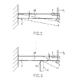
- the locking body 4 takes either a first position in which the lever tabs 29 are supported by the extensions 15 or a second position in which the extensions 15 into the slots 30 of the first Intervene friction device 7. In the second position, the lever tabs touch 29 of the first friction device 7 and the locking disks 17, 18 of the locking body 4 not, so that no support of the lever tabs 29 given by the locking body 4 is.
- the blocking body 4 is switched from its second position by means of the switching device 21 rotated, the extensions 15 leave the slots 30 in the first friction device 7 and move in the radial direction between the shaft 6 and the individual Lever tabs 29 until the first position is reached.
- the extensions 15 are preferably in their axial view rectangular. It is also possible to make them sawtooth-shaped, so that depending on the degree of rotation of the locking body 4, the support of Lever tabs 29 increases. The maximum support is reached when the Tips of the saw teeth from the slots 30 were rotated behind the lever tabs 29. It is also conceivable to design the blocking body 4 so that the extensions 15 do not extend in a plane perpendicular to the central axis M of the shaft 6, but on one Helix on a cylinder jacket around the central axis M of the shaft 6. This can support the individual lever tabs 29 is achieved at different points become, whereby the lever arm lengths change in the axial direction.
- the position of the extension 15 of the locking disk 4 to support the first friction device 7 in the axial direction is selected so that when the base body 2 is subjected to normal stress, for example when supported with an arm, the force is insufficient to engage the two friction devices 7 To solve 8. If, on the other hand, the force F 2 is exceeded, the base body 2 is rotated against the locking body 3 about the central axis M of the shaft 6 without the armrest 1 being damaged. This is because the toothing between the first and second friction devices 7, 8 is released. The armrest 1 can thus continue to be used even after a very high force has acted on it. The base body 2 of the armrest 1 is moved back into the desired position by moving the switching device 21 back into such a position that the locking disk 4 assumes the second position shown in FIG.
- the base body 2 can be rotated against a small force F 1 , as described above.
- the switching device 21 is brought back into its other position, so that the locking disk 4 is rotated back into its first position shown in FIG. 3.
- a fixed one Shaft 6 has a seat 11 in which a connecting body 9 engages in a form-fitting manner.
- a locking body 3 is rigidly connected, so that this both parts can not be rotated against each other.
- the locking body 3 is essentially constructed as that described in Fig. 1.
- With the second friction device 8 of the locking body 3 is the first friction device 7 of the base body 2, the structure of which is described in FIG. 1, engages.
- the base body 2 is thereby rotatably arranged on the connecting body 9. It is positioned axially on the one hand by the locking body 3 and on the other hand by a how 1, holding disc 14 held.
- Holding disc 14 is not rigidly connected to the shaft 6 by means of a screw 28, but instead by means of an elastic element 12 in the form of a coil spring.
- the coil spring is guided through a passage 13 in the connecting body 9. She is at her one End firmly connected to the holding disc 14 and at its other end to the shaft 6.
- a pin 41 is formed in a recess in the shaft 6.
- the mechanics on End of armrest 1 remote from the shaft is covered by a cover cap 25, as in FIG. 1, which is pressed onto the holding disc 14.
- the seat 11 on the shaft 6 is designed as a square.
- a connecting part 10 engages in it of the connecting body 9 in a form-fitting manner.
- the lateral overload protection works in such a way that with a force acting in the axial direction of the Shaft 6 is exerted on the base body 2, this together with the connecting body 9 rotated out of the seat 11 of the shaft 6 against the spring force of the elastic element 12 becomes. If this force diminishes, the connecting body 9 moves with it Connection part 10 due to the spring force back to the seat 11 and snaps into it automatically as soon as the force falls below a predetermined minimum. It is also possible, design the overload protection so that there are stationary positions in which the connecting part 9 is located outside the seat 11, as is the case with side mirrors Automobiles is known. The base body 2 engages with the connecting part 9 by means of a known mechanism, not described in more detail in these positions. The base body 2 is moved back into the seat 11 of the shaft 6 in that the latching position is overcome by light pressure and the base body 2 itself then automatically moves back to the normal position as described above.
Landscapes
- Engineering & Computer Science (AREA)
- Aviation & Aerospace Engineering (AREA)
- Transportation (AREA)
- Mechanical Engineering (AREA)
- Seats For Vehicles (AREA)
- Forklifts And Lifting Vehicles (AREA)
Abstract
Description
- Fig. 1
- einen Querschnitt durch ein erstes erfindungsgemäßes Ausführungsbeispiel Armlehme mit azimutaler Überlastsicherung,
- Fig. 2
- einen schematischen Ausschnitt des Ausführungsbeispiels von Fig. 1, wobei die Sperrscheibe in ihrer zweiten Position steht,
- Fig. 3
- einen Ausschnitt wie in Fig. 2, wobei die Sperrscheibe jedoch in ihrer ersten Position steht, und
- Fig. 4
- einen Querschnitt in der gleichen Ebene wie in Fig. 1 durch ein zweites Ausführungsbeispiel einer erfindungsgemäßen Armlehne mit lateraler Überlastsicherung.
- 1
- Armlehne
- 2
- Grundkörper
- 3
- Verriegelungskörper
- 4
- Sperrkörper
- 5
- Duchgang
- 6
- Welle
- 7
- Erste Reibungseinrichtung
- 8
- Zweite Reibungseinrichtung
- 9
- Verbindungskörper
- 10
- Anschlußteil
- 11
- Sitz
- 12
- Elastisches Element
- 13
- Durchgang
- 14
- Haltescheibe
- 15
- Fortsatz
- 16
- Erste Sperrscheibe
- 17
- Zweite Sperrscheibe
- 18
- Erste Ausnehmung
- 19
- Zweite Ausnehmung
- 20
- Durchbruch
- 21
- Umschaltvorrichtung
- 22
- Festlegemittel
- 23
- Erste Anschlagfläche
- 24
- Zweite Anschlagfläche
- 25
- Abdeckkappe
- 26
- Mutter
- 27
- Befestigungsscheibe
- 28
- Schraube
- 29
- Hebellaschen
- 30
- Schlitz
- 31
- Erste Schraube
- 32
- Zweite Schraube
- 33
- Äußere Erhebung des Grundkörpers
- 34
- Mittlere Erhebung des Grundkörpers
- 35
- Innere Erhebung des Grundkörpers
- 36
- Scheibe des Grundkörpers
- 37
- Äußere Erhebung des Verriegelungskörpers
- 38
- Mittlere Erhebung des Verriegelungskörpers
- 39
- Innere Erhebung des Verriegelungskörpers
- 40
- Scheibe des Verriegelungskörpers
- 41
- Zapfen
- F1, F2
- Kräfte
- M
- Mittelachse
- α, β
- Winkel
Claims (10)
- Armlehne (1) mit Überlastsicherung, insbesondere für einen Gabelstaplersitz, mit einem mit der Armlehne (1) fest verbundenen Grundkörper (2), einem fest dem Sitz zugeordneten Verriegelungskörper (3) und einem Sperrkörper (4), wobei Grundkörper (2), Verriegelungskörper (3) und Sperrkörper (4) konzentrisch um eine fest am Sitz montierte Welle (6) angeordnet sind, der Grundkörper (2) eine erste Reibungseinrichtung (7) und der Verriegelungskörper (3) eine zweite Reibungseinrichtung (8) aufweist, die beiden Reibungseinrichtungen (7, 8) konzentrisch zur Welle (6) in radialer Richtung in Kontakt sind und der Sperrkörper (4) eine der beiden Reibungseinrichtungen (7, 8) so in radialer Richtung unterstützt, dass bei Überlast die beiden Reibungseinrichtungen (7, 8) gegeneinander verdrehbar sind.
- Armlehne nach Anspruch 1, bei der der Sperrkörper (4) mittels einer Umschaltvorrichtung (21) zwischen einer ersten Position, in der er die erste oder zweite Reibungseinrichtung (7, 8) unterstützt, und einer zweiten Position, in der er keine der Reibungseinrichtungen (7, 8) unterstützt, bewegbar ist.
- Armlehne nach einem der Ansprüche 1 oder 2, wobei die Armlehne bei Überlastung mit einem Moment senkrecht zur Achse der Welle (6) in Kraftwirkungsrichtung schwenkbar ist.
- Armlehne nach einem der Ansprüche 1 bis 3 mit einem Grundkörper (2), der drehbar auf einem Verbindungskörper (9) angeordnet ist, wobei der Verbindungskörper (9) ein Anschlußteil (10) aufweist, das formschlüssig in einen Sitz (11) an einer feststehenden Welle (6) einsetzbar ist, und sowohl am Verbindungskörper (9) als auch am Sitz (11) ein elastisches Element (12) angreift, das den Verbindungskörper (9) in den Sitz (11) zieht.
- Armlehne (1) nach einem der vorstehenden Ansprüche, bei der die erste und zweite Reibungseinrichtung (7, 8) an einander zugewandten Flächen jeweils als ein Rillenprofil, insbesondere als ein Zahnkranz, ausgebildet sind.
- Armlehne (1) nach einem der vorstehenden Ansprüche, bei der der Sperrkörper (4) in radialer Richtung Fortsätze (15) aufweist, die erste oder zweite Reibungseinrichtung (7, 8) unterstützen.
- Armlehne (1) nach einem der vorstehenden Ansprüche, bei der der Sperrkörper (4) zwei Sperrscheiben (16, 17) aufweist, die in jeweils einer Ausnehmung (18, 19) des Grundkörpers (2) angeordnet sind und miteinander durch einen Durchbruch (20) im Grundkörper (2) verbunden sind.
- Armlehne (1) nach einem der vorstehenden Ansprüche, bei der der Grundkörper (2) zwischen einer waagerechten Position und einer senkrechten Position automatisch mittels einer Positioniervorrichtung bewegbar ist.
- Armlehne (1) nach Anspruch 8, bei der der Grundkörper (2) durch die Postioniervorrichtung in eine waagrechte Position bewegbar ist, wenn der der Armlehne (1) zugeordnete Sitz belastet ist, und der Grundkörper (2) in eine senkrechte Position bewegbar ist, wenn der Sitz nicht belastet ist.
- Armlehne (1) nach Anspruch 8 oder 9, bei der der Grundkörper (2) in seiner waagerechten Position mittels einer Arretiervorrichtung verriegelbar ist.
Applications Claiming Priority (2)
| Application Number | Priority Date | Filing Date | Title |
|---|---|---|---|
| DE10025396A DE10025396C2 (de) | 2000-05-23 | 2000-05-23 | Armlehne |
| DE10025396 | 2000-05-23 |
Publications (2)
| Publication Number | Publication Date |
|---|---|
| EP1157883A2 true EP1157883A2 (de) | 2001-11-28 |
| EP1157883A3 EP1157883A3 (de) | 2003-10-15 |
Family
ID=7643174
Family Applications (1)
| Application Number | Title | Priority Date | Filing Date |
|---|---|---|---|
| EP01112506A Withdrawn EP1157883A3 (de) | 2000-05-23 | 2001-05-23 | Armlehne |
Country Status (2)
| Country | Link |
|---|---|
| EP (1) | EP1157883A3 (de) |
| DE (1) | DE10025396C2 (de) |
Cited By (2)
| Publication number | Priority date | Publication date | Assignee | Title |
|---|---|---|---|---|
| WO2003082626A1 (de) * | 2002-03-30 | 2003-10-09 | Volkswagen Aktiengesellschaft | Armlehne für ein fahrzeug, insbesondere für ein kraftfahrzeug |
| EP1361107A3 (de) * | 2002-05-08 | 2004-11-17 | Seeber AG & Co. KG | Deckelteil, inbesondere für ein Kraftfahrzeug |
Families Citing this family (2)
| Publication number | Priority date | Publication date | Assignee | Title |
|---|---|---|---|---|
| DE10345677B4 (de) * | 2003-10-01 | 2013-11-14 | Volkswagen Ag | Schwenklager zur schwenkbaren Lagerung einer Armlehne an einem Sitz in einem Verkehrsmittel |
| DE102005027992B4 (de) * | 2005-06-17 | 2013-07-18 | Audi Ag | Armlehne |
Family Cites Families (5)
| Publication number | Priority date | Publication date | Assignee | Title |
|---|---|---|---|---|
| DE590147C (de) * | 1935-05-22 | Wilhelm Brase | Als Umlaufraedergetriebe ausgebildetes Zweiganggetriebe, insbesondere fuer Kraftfahrzeuge | |
| DE2714581A1 (de) * | 1977-04-01 | 1978-10-05 | Daimler Benz Ag | Schwenkbare armstuetze |
| DE4227871A1 (de) * | 1992-08-22 | 1994-02-24 | Schmidt Gmbh R | Schwenkbares Funktionsteil als Ausstattung eines Kraftfahrzeuges |
| US5290087A (en) * | 1992-10-19 | 1994-03-01 | Prince Corporation | Armrest with impact dependent dimension |
| DE19734334C2 (de) * | 1997-08-08 | 2002-06-27 | Fehrer F S Gmbh & Co Kg | Mittelarmlehne mit rückstellbarem Überlastschutz |
-
2000
- 2000-05-23 DE DE10025396A patent/DE10025396C2/de not_active Expired - Fee Related
-
2001
- 2001-05-23 EP EP01112506A patent/EP1157883A3/de not_active Withdrawn
Non-Patent Citations (1)
| Title |
|---|
| None |
Cited By (4)
| Publication number | Priority date | Publication date | Assignee | Title |
|---|---|---|---|---|
| WO2003082626A1 (de) * | 2002-03-30 | 2003-10-09 | Volkswagen Aktiengesellschaft | Armlehne für ein fahrzeug, insbesondere für ein kraftfahrzeug |
| CN100519265C (zh) * | 2002-03-30 | 2009-07-29 | 大众汽车有限公司 | 用于车辆的扶手 |
| DE10214469B4 (de) * | 2002-03-30 | 2012-02-02 | Volkswagen Ag | Armlehne für ein Fahrzeug, insbesondere für ein Kraftfahrzeug |
| EP1361107A3 (de) * | 2002-05-08 | 2004-11-17 | Seeber AG & Co. KG | Deckelteil, inbesondere für ein Kraftfahrzeug |
Also Published As
| Publication number | Publication date |
|---|---|
| EP1157883A3 (de) | 2003-10-15 |
| DE10025396A1 (de) | 2002-05-08 |
| DE10025396C2 (de) | 2003-05-08 |
Similar Documents
| Publication | Publication Date | Title |
|---|---|---|
| DE3429424C2 (de) | ||
| DE69310834T2 (de) | Vorrichtung für die Neigungsverstellung von Bett- oder Sofateilen | |
| DE2831201A1 (de) | Vorrichtung zum verstellen zweier beweglicher teile zueinander unter ausgleich des zwischen den teilen bestehenden spiels | |
| DE20106081U1 (de) | Lösemechanismus für eine Teleskopgleitschienenanordnung | |
| DE102013202436A1 (de) | Lenksäulenteleskop und E/A-Verriegelungsvorrichtung | |
| DE2338304A1 (de) | Drehmomentschluessel | |
| DE112019000690T5 (de) | Doppelter energiespeicher-betriebsmechanismus eines trennschalters | |
| DE3412139A1 (de) | Stellmechanismus | |
| DE4021037A1 (de) | Elektrische bohrmaschine mit geschwindigkeits- und drehkraftregelung | |
| DE102017121146A1 (de) | Formschluss-Feststelleinrichtung für eine Rolle | |
| EP4249171A2 (de) | Als knarre verwendbarer drehmomentschlüssel | |
| EP3990804B1 (de) | Spielfreies planetenradgetriebe | |
| EP1284447A1 (de) | Schwenkbeschlag | |
| EP3891041B1 (de) | Spannvorrichtung für eine lenksäule und lenksäule für ein kraftfahrzeug | |
| EP0995371B1 (de) | Bürostuhl mit einer Sitzneigungsverstellung | |
| DE102007018029B3 (de) | Stativkopf | |
| DE1914550C3 (de) | Schraubenspindelgetriebe für eine Hebewinde oder dergl | |
| DE3126694C2 (de) | ||
| EP1157883A2 (de) | Armlehne | |
| DE69705550T2 (de) | Steckverbinder mit Verriegelungshebel | |
| EP3498941A1 (de) | Betätigungshandhabe mit sperrvorrichtung | |
| DE2935420B1 (de) | Elektrische Ausschaltvorrichtung,insbesondere Seilzugnotschaltvorrichtung | |
| DE7815650U1 (de) | Einrastvorrichtung fuer einstellscheiben | |
| DE102020125388A1 (de) | Elektrowerkzeugstruktur | |
| WO1998040593A1 (de) | Vorrichtung mit einem beweglichen teil |
Legal Events
| Date | Code | Title | Description |
|---|---|---|---|
| PUAI | Public reference made under article 153(3) epc to a published international application that has entered the european phase |
Free format text: ORIGINAL CODE: 0009012 |
|
| AK | Designated contracting states |
Kind code of ref document: A2 Designated state(s): AT BE CH CY DE DK ES FI FR GB GR IE IT LI LU MC NL PT SE TR |
|
| AX | Request for extension of the european patent |
Free format text: AL;LT;LV;MK;RO;SI |
|
| PUAL | Search report despatched |
Free format text: ORIGINAL CODE: 0009013 |
|
| AK | Designated contracting states |
Kind code of ref document: A3 Designated state(s): AT BE CH CY DE DK ES FI FR GB GR IE IT LI LU MC NL PT SE TR |
|
| AX | Request for extension of the european patent |
Extension state: AL LT LV MK RO SI |
|
| STAA | Information on the status of an ep patent application or granted ep patent |
Free format text: STATUS: THE APPLICATION IS DEEMED TO BE WITHDRAWN |
|
| 18D | Application deemed to be withdrawn |
Effective date: 20031202 |
|
| REG | Reference to a national code |
Ref country code: DE Ref legal event code: 8566 |