EP1157835B2 - Inking device of rotary press - Google Patents
Inking device of rotary press Download PDFInfo
- Publication number
- EP1157835B2 EP1157835B2 EP01111981A EP01111981A EP1157835B2 EP 1157835 B2 EP1157835 B2 EP 1157835B2 EP 01111981 A EP01111981 A EP 01111981A EP 01111981 A EP01111981 A EP 01111981A EP 1157835 B2 EP1157835 B2 EP 1157835B2
- Authority
- EP
- European Patent Office
- Prior art keywords
- ink fountain
- hook
- engagement
- engagement pin
- fountain device
- Prior art date
- Legal status (The legal status is an assumption and is not a legal conclusion. Google has not performed a legal analysis and makes no representation as to the accuracy of the status listed.)
- Expired - Lifetime
Links
Images
Classifications
-
- B—PERFORMING OPERATIONS; TRANSPORTING
- B41—PRINTING; LINING MACHINES; TYPEWRITERS; STAMPS
- B41F—PRINTING MACHINES OR PRESSES
- B41F31/00—Inking arrangements or devices
- B41F31/02—Ducts, containers, supply or metering devices
- B41F31/04—Ducts, containers, supply or metering devices with duct-blades or like metering devices
Definitions
- This invention relates to an inking device of a rotary press.
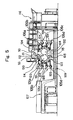
- FIG. 5 there has been a four-color double-sided simultaneous offset printing press as shown, for example, in FIG. 5 (see Japanese Patent No. 2612594 ).
- a blanketed impression cylinder 101 with a paper gripping device and a blanket cylinder 102 without a paper gripping device are supported in a nearly horizontal position in a printing unit 100, with the circumferential surfaces of the blanketed impression cylinder 101 and the blanket cylinder 102 being in contact with each other.
- Four plate cylinders 103 are arranged on the circumferential surface of the blanketed impression cylinder 101, and four plate cylinders 104 are similarly arranged on the circumferential surface of the blanket cylinder 102.
- Inking units 105, 106 are provided to be movable toward and away from the plate cylinders 103, 104, and can supply ink and water while contacting the plate cylinders 103, 104.
- a delivery cylinder 108 of a delivery unit 107 is disposed below the blanketed impression cylinder 101, and a chain 109 is disposed leftward of the delivery cylinder 108 without crossing a space below a position of contact between the circumferential surfaces of the blanketed impression cylinder 101 and the blanket cylinder 102.
- Transfer cylinders 111 to 114 with paper gripping devices are provided for transferring a sheet from a register 110 to the blanketed impression cylinder 101.
- a transfer cylinder 115 with a paper gripping device is provided for transferring a sheet from the blanketed impression cylinder 101 to the delivery cylinder 108.
- Numeral 116 denotes a feeder.
- a sheet fed from the feeder 116 and positioned by the register 110 is transported along a route indicated by arrows in the drawing, namely, along the circumferential surfaces of the transfer cylinders 111 to 114, blanketed impression cylinder 101, transfer cylinder 115, and delivery cylinder 108 in this order.
- the sheet passes through the point of contact between the blanketed impression cylinder 101 and the blanket cylinder 102 downwardly from above, both sides of the sheet are printed simultaneously.
- inking devices 105a to 105d, 106a to 106d for four colors are provided.
- These inking devices 105a to 105d, 106a to 106d each have an ink fountain roller rotating with a shaft thereof rotatably supported by right and left frames, and an ink fountain device has a triangular cross sectional shape formed by the circumferential surface of the ink fountain roller, dam plates at the ends of the ink fountain device, and ink blade sections.
- Ink stored in the ink fountain device flows out from a gap between the circumferential surface of the ink fountain roller and the front ends of the ink blade sections upon rotation of the ink fountain roller, and the ink adheres to the circumferential surface of the ink fountain roller.
- an ink distribution roller parallel thereto is rotatably disposed.
- the ink, adhered to the circumferential surface of the ink fountain roller, is transferred to the ink distribution roller by an ink ductor roller which is supported by an arm and reciprocates between the ink fountain roller and the ink distribution roller upon swaying of the arm. Then, the ink is uniformly flattened in different directions while being transferred among many groups of ink rollers, whereafter the ink is supplied to a plate surface on the plate cylinder by ink form rollers.
- the ink fountain device has conventionally been switchable between two positions, i.e., an ink fountain position during printing (fixed position), and an ink fountain position during cleaning, adjustment, or long-term machine shutdown (throw-off position).
- an ink fountain position during printing fixed position
- an ink fountain position during cleaning, adjustment, or long-term machine shutdown long-term machine shutdown
- the ink fountain device can be switched only between two positions as stated above.
- a space in a vertical direction between the unused ink fountain devices and the ink fountain devices, in use, located below them becomes small. This has made it difficult to secure a vertical space for operating the ink fountain.
- the conventional ink fountain device is fixed by the bolt-nut fixing method relying on the operator's manual work.
- US-A-5 533 450 relates to an inking device of a rotary press comprising an ink fountain roller supported rotatably, an ink fountain device movable among a fixed position in which said ink fountain device is located at a position close to said ink fountain roller and a throw-off position in which said ink fountain device is separated from said ink fountain roller, and switching means for switching said ink fountain device among said fixed position and said throw-off position, the switching means include a locking handle and a hole releasably supported on an engagement pin provided on said ink fountain device, wherein said locking handle can be held at one position at which said ink fountain device is held at said fixed position, with said hook being engaged with said engagement pin, and said locking handle can move to another position at which engagement between said hook and said engagement pin can be released.
- the present invention has been conceived in consideration of the above-mentioned problems with the earlier technology. It is an object of the present invention to provide an inking device of a rotary press which makes it easy to secure a vertical space for operating an ink fountain, and which can fix an ink fountain device with a constant clamping force without using a tool.
- the present invention which attains the above object, is an inking device according to claim 1.
- the ink fountain device may have a first spring member for pressing the ink fountain device when the ink fountain device is located at the fixed position to prevent backlash of the ink fountain device by the first spring member.
- the switching means comprise an eccentric pin rotatably supported by at least one of the frames, a locking handle fixedly provided on the eccentric pin, and a hook pivotably fitted onto an eccentric shaft portion of the eccentric pin, and releasably supported on an engagement pin provided on the ink fountain device.
- the locking handle can be held at a first position, at which the ink fountain device is held at the fixed position, with the hook being engaged with the engagement pin, and a second position, at which the ink fountain device is held at the intermediate position, with the hook being engaged with the engagement pin.
- the locking handle can also move to a third position at which engagement between the hook and the engagement pin can be released.
- Holding means for holding the locking handle at each of the first position, the second position, and the third position may be provided.
- the holding means may comprise grooves, an engagement member for engaging the groove, and a second spring member for urging the engagement member in a direction in which the engagement member engages the groove.
- Release means may be provided for releasing the hook from the engagement pin when the locking handle is located at the third position, and the hook may be disengaged from the engagement pin by moving the ink fountain device upward.
- the release means may have a third spring member for urging the hook in a direction in which engagement of the hook with the engagement pin is released, when the locking handle is located at the third position, and for releasing an urging force on the hook when the locking handle is located at the first position or the second position.
- the engagement pin may be engaged with the hook by upwardly moving the ink fountain device located at the throw-off position when the locking handle is located at the second position.
- the hook may have, at a front end thereof, an inclined surface raised by the engagement pin.
- the hook raised by the engagement pin may engage the engagement pin by the own weight of the hook.
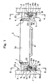
- FIG. 1 is a plan view of an inking device of a rotary press according to an embodiment of the present invention.
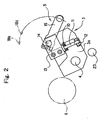
- FIG. 2 is a sectional view taken along line A-A of FIG. 1 .
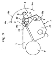
- FIG. 3 is a sectional view taken along line B-B of FIG. 1 .
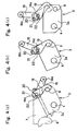
- FIGS. 4(a) to 4(c) are explanatory drawings of a switching motion of an ink fountain device.
- an ink fountain device 3 is pivotably supported by pivot shafts 4 between left and right frames 1, 2 of a rotary press.
- the ink fountain device 3 can be moved by left and right switching means 5 as a pair (to be described later) toward and away from an ink fountain roller 6 which has a shaft similarly supported rotatably between the left and right frames 1, 2.
- the ink fountain device 3 has left and right dam plates 7, as a pair, fixedly provided on an upper surface portion of an ink fountain body 3a, and also has an ink fountain handle 8 fixedly provided on a front surface portion of the ink fountain body 3a.
- Engagement pins 9 are provided projectingly on left and right end surface portions of the ink fountain body 3a.
- Bolts 11 for preventing backlash which are urged by coned disc springs 10, are assembled with stopper nuts 12 to left and right end portions of the ink fountain body 3a.
- the bolts 11 for preventing backlash are pressed against the lower surfaces of brackets 13 mounted projectingly on the inner surfaces of the left and right frames 1, 2 to prevent backlash of shaft supports of the ink fountain device 3.
- the switching means 5 comprises an eccentric pin 14 penetrating the bracket 13 and rotatably supported by the left or right frame 1 or 2, and a locking handle 15 fixedly provided at a base end portion of the eccentric pin 14 for revolvingly operating the eccentric pin 14.
- a steel ball 17, urged by a spring 16, is assembled to a front end portion of the locking handle 15.
- the steel ball 17 selectively engages any of three engagement grooves 18a, 18b, and 18c formed in the inner surface of the left or right frame 1 or 2, whereby the ink fountain device 3 is located at each of a fixed position (corresponding to the engagement groove 18a) close to the ink fountain roller 6 at the time of printing, a throw-off position (corresponding to the engagement groove 18b) during cleaning, adjustment, or long-term machine shutdown, and an intermediate position (corresponding to the engagement groove 18c) at which the ink fountain device 3 is temporarily fixed between the fixed position and the throw-off position.
- a hook 19 is pivotably fitted onto an eccentric shaft portion 14a at the front end of the eccentric pin 14. The hook 19 engages the engagement pin 9 when the ink fountain device 3 is located at the fixed position or the intermediate position.
- the hook 19 has at its front end portion an inclined surface 19a to be raised by the engagement pin 9.
- a plunger (release means) 21, urged by a spring, is provided at an intermediate shaft portion 14b of the eccentric pin 14 via a support block 20.
- the plunger 21 is pressed against a stopper pin (release means) 22 annexed to the side surface of the hook 19 to release the hook 19 from the engagement pin 9.
- Numeral 23 denotes a stopper at the throw-off position of the ink fountain device 3.
- FIG. 4(a) shows switching to the fixed position of the ink fountain device 3 during printing when the ink fountain device 3 approaches the ink fountain roller 6.
- the steel ball 17 of the locking handle 15 is urged by the spring 16, and engaged with the engagement groove 18a of the left or right frame 1 or 2.
- the hook 19, supported by the eccentric shaft portion 14a of the eccentric pin 14 engages the engagement pin 9 of the ink fountain body 3a, so that this state is stably maintained.
- the head of the bolt 11 on the ink fountain body 3a is urged by the coned disc spring 10, and pressed against the lower surface of the bracket 13 at the side of the left or right frame 1 or 2.
- the ink fountain body 3a is always pivotally urged in a clockwise direction about the pivot shaft 4. Consequently, backlash at support shaft portions, such as the pivot shaft 4 and the eccentric pin 14 (eccentric shaft portion 14a), is prevented, and the ink fountain device 3 is fixed with high accuracy. That is, the ink fountain device 3 is fixed at the fixed position with a constant clamping force without using a special tool, so that highly accurate ink supply is achieved.
- FIG. 4(b) shows switching to the intermediate position of the ink fountain device 3 (temporary fixed position at which the ink fountain device 3 is not used temporarily).
- the steel ball 17 of the locking handle 15 is urged by the spring 16, and engaged with the engagement groove 18c of the left or right frame 1 or 2.
- the hook 19 is slightly displaced downward relative to the left or right frame 1 or 2 by the eccentric action of the eccentric shaft portion 14a in accordance with the counterclockwise revolution of the eccentric pin 14.
- the ink fountain body 3a, engaging the hook 19 via the engagement pin 9 slightly pivots in a clockwise direction about the pivot shaft 4.
- ink fountain key (not shown) being set on the ink fountain body 3a
- the front ends of ink blade sections (not shown) can be kept away from the circumferential surface of the ink fountain roller 6.
- the ink fountain body 3a is only slightly displaced downward from the fixed position to a position different from a throw-off position to be described later.
- sufficient space can be secured below this position.
- unused ink fountain devices 3 exist in a four-color double-sided simultaneous offset printing press with ink fountain devices 3 arranged vertically in multiple stages, an ample vertical space can be secured for operating the ink fountain in the ink fountain devices 3 in use and located below the unused ink fountain devices 3.
- FIG. 4(c) shows switching to the throw-off position during cleaning, adjusting, or long-term machine shutdown of the ink fountain device 3.
- the steel ball 17 of the locking handle 15 is urged by the spring 16, and engaged with the engagement groove 18b of the left or right frame 1 or 2.
- the front end of the plunger 21 is pressed against the stopper pin 22 annexed to the hook 19 to pivotally urge the hook 19 in a counterclockwise direction about the eccentric shaft portion 14a.
- the ink fountain handle 8 is operated to turn (lift) the ink fountain body 3a slightly in the counterclockwise direction about the pivot shaft 4, whereby the hook 19 automatically departs from the engagement pin 9 of the ink fountain body 3a. Then, the ink fountain body 3a, as such, is lowered until it contacts the stopper 23, whereby the ink fountain device 3 is located at the throw-off position.
- the ink fountain device 3 is switched, easily, promptly, and with high accuracy by a handle operation, among the fixed position at the time of printing, the throw-off position during cleaning, adjusting, or long-term machine shutdown, and the intermediate position at which the ink fountain device 3 is temporarily fixed between the fixed position and the throw-off position. Furthermore, an ample vertical space for operating the ink fountain can be secured by switching to the intermediate position.
- the locking handle 15 is returned to the engagement groove 18c corresponding to the intermediate position of the ink fountain device 3.
- the release means for releasing the engagement between the hook and the engagement pin may be changed to other structures.
- the coned plate spring 10 may be provided on each of the frames 1, 2.
- the switching means 5 need not be provided on both frames (the same is true of the engagement pin 9).
- the locking handle 15 need not be held at the throw-off position (for example, the locking handle may be brought by the left hand to the throw-off position, and the ink fountain handle 8 may be operated by the right hand).
Landscapes
- Inking, Control Or Cleaning Of Printing Machines (AREA)
- Dot-Matrix Printers And Others (AREA)
- Coating Apparatus (AREA)
- Rotary Presses (AREA)
Priority Applications (1)
| Application Number | Priority Date | Filing Date | Title |
|---|---|---|---|
| DE60121503T DE60121503T3 (de) | 2000-05-24 | 2001-05-22 | Farbvorrichtung für eine Rotationsdruckmaschine |
Applications Claiming Priority (2)
| Application Number | Priority Date | Filing Date | Title |
|---|---|---|---|
| JP2000152437A JP4540183B2 (ja) | 2000-05-24 | 2000-05-24 | 輪転印刷機のインキ装置 |
| JP2000152437 | 2000-05-24 |
Publications (3)
| Publication Number | Publication Date |
|---|---|
| EP1157835A1 EP1157835A1 (en) | 2001-11-28 |
| EP1157835B1 EP1157835B1 (en) | 2006-07-19 |
| EP1157835B2 true EP1157835B2 (en) | 2011-06-22 |
Family
ID=18657863
Family Applications (1)
| Application Number | Title | Priority Date | Filing Date |
|---|---|---|---|
| EP01111981A Expired - Lifetime EP1157835B2 (en) | 2000-05-24 | 2001-05-22 | Inking device of rotary press |
Country Status (6)
| Country | Link |
|---|---|
| US (1) | US6546864B2 (enExample) |
| EP (1) | EP1157835B2 (enExample) |
| JP (1) | JP4540183B2 (enExample) |
| AT (1) | ATE333369T1 (enExample) |
| DE (1) | DE60121503T3 (enExample) |
| ES (1) | ES2269249T3 (enExample) |
Families Citing this family (1)
| Publication number | Priority date | Publication date | Assignee | Title |
|---|---|---|---|---|
| US8939078B2 (en) | 2011-08-17 | 2015-01-27 | Komori Corporation | Ink supply apparatus of printing press |
Citations (2)
| Publication number | Priority date | Publication date | Assignee | Title |
|---|---|---|---|---|
| DE7042195U (de) † | 1971-02-18 | Man Ag | Einrichtung zur Farbmengenregelung an Rotationsdruckmaschinen | |
| US4123972A (en) † | 1977-05-12 | 1978-11-07 | Baldwin-Gegenheimer Corporation | Positioning mechanism for locating the edge of an ink metering means |
Family Cites Families (18)
| Publication number | Priority date | Publication date | Assignee | Title |
|---|---|---|---|---|
| US2887049A (en) * | 1955-12-29 | 1959-05-19 | Harris Intertype Corp | Ink fountain |
| US3589288A (en) | 1969-04-03 | 1971-06-29 | Addressograph Multigraph | Ink fountain for dispensing packaged ink |
| JPS50150402U (enExample) * | 1974-05-31 | 1975-12-15 | ||
| US4130057A (en) * | 1977-10-25 | 1978-12-19 | Roland Offsetmaschinenfabrik Faber & Schleicher Ag. | Dampening system for printing presses, particularly offset printing presses |
| EP0040192A1 (en) * | 1979-11-05 | 1981-11-25 | Dahlgren Manufacturing Company | Portable ink fountain |
| DE8034726U1 (de) * | 1980-12-29 | 1981-05-27 | M.A.N.- Roland Druckmaschinen AG, 6050 Offenbach | Vorrichtung zum trennen von bereichen des farbauftrags an farbkaesten fuer druckmaschinen |
| FR2527987B1 (fr) * | 1982-06-04 | 1986-06-20 | Creusot Loire | Dispositif d'encrage a lame basse a cuvettes d'encrier amovibles |
| DE3312128C2 (de) * | 1983-04-02 | 1986-04-03 | M.A.N.- Roland Druckmaschinen AG, 6050 Offenbach | Vorrichtung an Druckmaschinen mit einer Einrichtung zum Lackieren von Druckbögen |
| US4700631A (en) * | 1985-05-30 | 1987-10-20 | Apollo Labeling Systems | Ink fountain and ink fountain support for printing press |
| DE3624572A1 (de) * | 1986-07-21 | 1988-02-04 | Heidelberger Druckmasch Ag | Farbkasten fuer offset- oder hochdruckmaschinen mit farbdosiereinrichtung |
| US5161465A (en) * | 1988-08-19 | 1992-11-10 | Presstek, Inc. | Method of extending the useful life and enhancing performance of lithographic printing plates |
| JPH02187337A (ja) * | 1989-01-13 | 1990-07-23 | Komori Printing Mach Co Ltd | コンビネーシヨン枚葉輪転印刷機 |
| DE8912194U1 (de) * | 1989-10-13 | 1989-11-23 | MAN Roland Druckmaschinen AG, 6050 Offenbach | Farbwerk |
| JPH0366030U (enExample) * | 1989-10-23 | 1991-06-27 | ||
| DE4410305C2 (de) * | 1994-03-25 | 1997-02-06 | Roland Man Druckmasch | Aufhängung für eine als Schutz vor den Druckwerkszylindern einer Druckmaschine dienenden Einrichtung |
| JP2819248B2 (ja) * | 1994-11-28 | 1998-10-30 | 株式会社東京機械製作所 | 印刷機のインキ壺装置 |
| DE19629811A1 (de) * | 1996-07-24 | 1998-01-29 | Roland Man Druckmasch | Farbwerk für Rotationsdruckmaschinen |
| US6076463A (en) * | 1998-03-13 | 2000-06-20 | Heidelberger Druckmaschinen Ag | Ink metering device and method of metering ink |
-
2000
- 2000-05-24 JP JP2000152437A patent/JP4540183B2/ja not_active Expired - Fee Related
-
2001
- 2001-05-22 AT AT01111981T patent/ATE333369T1/de not_active IP Right Cessation
- 2001-05-22 EP EP01111981A patent/EP1157835B2/en not_active Expired - Lifetime
- 2001-05-22 DE DE60121503T patent/DE60121503T3/de not_active Expired - Lifetime
- 2001-05-22 ES ES01111981T patent/ES2269249T3/es not_active Expired - Lifetime
- 2001-05-24 US US09/863,517 patent/US6546864B2/en not_active Expired - Lifetime
Patent Citations (2)
| Publication number | Priority date | Publication date | Assignee | Title |
|---|---|---|---|---|
| DE7042195U (de) † | 1971-02-18 | Man Ag | Einrichtung zur Farbmengenregelung an Rotationsdruckmaschinen | |
| US4123972A (en) † | 1977-05-12 | 1978-11-07 | Baldwin-Gegenheimer Corporation | Positioning mechanism for locating the edge of an ink metering means |
Also Published As
| Publication number | Publication date |
|---|---|
| EP1157835B1 (en) | 2006-07-19 |
| US20010045168A1 (en) | 2001-11-29 |
| DE60121503T3 (de) | 2012-06-06 |
| DE60121503T2 (de) | 2007-07-26 |
| DE60121503D1 (de) | 2006-08-31 |
| US6546864B2 (en) | 2003-04-15 |
| JP2001328240A (ja) | 2001-11-27 |
| EP1157835A1 (en) | 2001-11-28 |
| ES2269249T3 (es) | 2007-04-01 |
| ATE333369T1 (de) | 2006-08-15 |
| JP4540183B2 (ja) | 2010-09-08 |
Similar Documents
| Publication | Publication Date | Title |
|---|---|---|
| CA2091203C (en) | Intaglio printing machine | |
| US4421027A (en) | Multiple printing mode printing machine system | |
| CA2190400C (en) | Counterpoise and lift mechanism | |
| CN1325252C (zh) | 凹版印刷机 | |
| EP1592555B1 (en) | Drive of the inking unit in an intaglio printing machine | |
| EP1667844B1 (en) | Rotary printing press | |
| JPH0776063A (ja) | 特に版胴をはじめとする少なくとも1つの交換可能のシリンダあるいは交換可能の刷版を有する印刷機械 | |
| JPH0420388B2 (enExample) | ||
| EP0982125B1 (en) | Multicolour intaglio printing press | |
| US6553907B2 (en) | Multi-color printing press with common blanket cylinder | |
| GB2270502A (en) | Inking unit for printing machines. | |
| US7963226B2 (en) | Method for operating a printing unit having at least one press unit, and a press unit for carrying out the method | |
| US20080295723A1 (en) | Printing press | |
| CN101468540A (zh) | 液体涂布机 | |
| EP1157835B2 (en) | Inking device of rotary press | |
| EP0275025B1 (en) | Inking device for printing apparatus | |
| US6874416B2 (en) | Printing press | |
| CA1066130A (en) | Ink ductor system | |
| CA2393209A1 (en) | Sheet-fed printing press and method carried out using the same | |
| US4932322A (en) | Swing away color head for offset duplicator | |
| US7055433B1 (en) | Method of operation of a printing unit and printing unit for offset machine | |
| US4896599A (en) | Swing-away colorhead for offset duplicator | |
| US20020185023A1 (en) | Printing unit with inker for varying-diameter plate cylinder | |
| EP1795350B1 (en) | Ink transport route switching method and apparatus in inking device of printing press | |
| JP2000127343A (ja) | 印刷機におけるロック装置、およびこれを備えた印刷機 |
Legal Events
| Date | Code | Title | Description |
|---|---|---|---|
| PUAI | Public reference made under article 153(3) epc to a published international application that has entered the european phase |
Free format text: ORIGINAL CODE: 0009012 |
|
| AK | Designated contracting states |
Kind code of ref document: A1 Designated state(s): AT BE CH CY DE DK ES FI FR GB GR IE IT LI LU MC NL PT SE TR |
|
| AX | Request for extension of the european patent |
Free format text: AL;LT;LV;MK;RO;SI |
|
| 17P | Request for examination filed |
Effective date: 20011220 |
|
| AKX | Designation fees paid |
Free format text: AT BE CH CY DE DK ES FI FR GB GR IE IT LI LU MC NL PT SE TR |
|
| GRAP | Despatch of communication of intention to grant a patent |
Free format text: ORIGINAL CODE: EPIDOSNIGR1 |
|
| GRAS | Grant fee paid |
Free format text: ORIGINAL CODE: EPIDOSNIGR3 |
|
| GRAA | (expected) grant |
Free format text: ORIGINAL CODE: 0009210 |
|
| AK | Designated contracting states |
Kind code of ref document: B1 Designated state(s): AT BE CH CY DE DK ES FI FR GB GR IE IT LI LU MC NL PT SE TR |
|
| PG25 | Lapsed in a contracting state [announced via postgrant information from national office to epo] |
Ref country code: AT Free format text: LAPSE BECAUSE OF FAILURE TO SUBMIT A TRANSLATION OF THE DESCRIPTION OR TO PAY THE FEE WITHIN THE PRESCRIBED TIME-LIMIT Effective date: 20060719 Ref country code: FI Free format text: LAPSE BECAUSE OF FAILURE TO SUBMIT A TRANSLATION OF THE DESCRIPTION OR TO PAY THE FEE WITHIN THE PRESCRIBED TIME-LIMIT Effective date: 20060719 Ref country code: BE Free format text: LAPSE BECAUSE OF FAILURE TO SUBMIT A TRANSLATION OF THE DESCRIPTION OR TO PAY THE FEE WITHIN THE PRESCRIBED TIME-LIMIT Effective date: 20060719 Ref country code: IT Free format text: LAPSE BECAUSE OF FAILURE TO SUBMIT A TRANSLATION OF THE DESCRIPTION OR TO PAY THE FEE WITHIN THE PRESCRIBED TIME-LIMIT;WARNING: LAPSES OF ITALIAN PATENTS WITH EFFECTIVE DATE BEFORE 2007 MAY HAVE OCCURRED AT ANY TIME BEFORE 2007. THE CORRECT EFFECTIVE DATE MAY BE DIFFERENT FROM THE ONE RECORDED. Effective date: 20060719 |
|
| REG | Reference to a national code |
Ref country code: GB Ref legal event code: FG4D |
|
| REG | Reference to a national code |
Ref country code: CH Ref legal event code: EP |
|
| REG | Reference to a national code |
Ref country code: IE Ref legal event code: FG4D |
|
| REF | Corresponds to: |
Ref document number: 60121503 Country of ref document: DE Date of ref document: 20060831 Kind code of ref document: P |
|
| REG | Reference to a national code |
Ref country code: SE Ref legal event code: TRGR |
|
| REG | Reference to a national code |
Ref country code: CH Ref legal event code: NV Representative=s name: R. A. EGLI & CO. PATENTANWAELTE |
|
| PG25 | Lapsed in a contracting state [announced via postgrant information from national office to epo] |
Ref country code: DK Free format text: LAPSE BECAUSE OF FAILURE TO SUBMIT A TRANSLATION OF THE DESCRIPTION OR TO PAY THE FEE WITHIN THE PRESCRIBED TIME-LIMIT Effective date: 20061019 |
|
| PG25 | Lapsed in a contracting state [announced via postgrant information from national office to epo] |
Ref country code: PT Free format text: LAPSE BECAUSE OF FAILURE TO SUBMIT A TRANSLATION OF THE DESCRIPTION OR TO PAY THE FEE WITHIN THE PRESCRIBED TIME-LIMIT Effective date: 20061219 |
|
| ET | Fr: translation filed | ||
| REG | Reference to a national code |
Ref country code: ES Ref legal event code: FG2A Ref document number: 2269249 Country of ref document: ES Kind code of ref document: T3 |
|
| PLBI | Opposition filed |
Free format text: ORIGINAL CODE: 0009260 |
|
| PLAX | Notice of opposition and request to file observation + time limit sent |
Free format text: ORIGINAL CODE: EPIDOSNOBS2 |
|
| 26 | Opposition filed |
Opponent name: KBA-GIORI S.A. Effective date: 20070417 |
|
| NLR1 | Nl: opposition has been filed with the epo |
Opponent name: KBA-GIORI S.A. |
|
| PLAF | Information modified related to communication of a notice of opposition and request to file observations + time limit |
Free format text: ORIGINAL CODE: EPIDOSCOBS2 |
|
| PLBB | Reply of patent proprietor to notice(s) of opposition received |
Free format text: ORIGINAL CODE: EPIDOSNOBS3 |
|
| PG25 | Lapsed in a contracting state [announced via postgrant information from national office to epo] |
Ref country code: MC Free format text: LAPSE BECAUSE OF NON-PAYMENT OF DUE FEES Effective date: 20070531 |
|
| PG25 | Lapsed in a contracting state [announced via postgrant information from national office to epo] |
Ref country code: GR Free format text: LAPSE BECAUSE OF FAILURE TO SUBMIT A TRANSLATION OF THE DESCRIPTION OR TO PAY THE FEE WITHIN THE PRESCRIBED TIME-LIMIT Effective date: 20061020 |
|
| PG25 | Lapsed in a contracting state [announced via postgrant information from national office to epo] |
Ref country code: IE Free format text: LAPSE BECAUSE OF NON-PAYMENT OF DUE FEES Effective date: 20070522 |
|
| PGFP | Annual fee paid to national office [announced via postgrant information from national office to epo] |
Ref country code: ES Payment date: 20090609 Year of fee payment: 9 Ref country code: NL Payment date: 20090517 Year of fee payment: 9 |
|
| PG25 | Lapsed in a contracting state [announced via postgrant information from national office to epo] |
Ref country code: LU Free format text: LAPSE BECAUSE OF NON-PAYMENT OF DUE FEES Effective date: 20070522 Ref country code: CY Free format text: LAPSE BECAUSE OF FAILURE TO SUBMIT A TRANSLATION OF THE DESCRIPTION OR TO PAY THE FEE WITHIN THE PRESCRIBED TIME-LIMIT Effective date: 20060719 |
|
| PGFP | Annual fee paid to national office [announced via postgrant information from national office to epo] |
Ref country code: FR Payment date: 20090515 Year of fee payment: 9 Ref country code: IT Payment date: 20090522 Year of fee payment: 9 Ref country code: SE Payment date: 20090512 Year of fee payment: 9 |
|
| PG25 | Lapsed in a contracting state [announced via postgrant information from national office to epo] |
Ref country code: TR Free format text: LAPSE BECAUSE OF FAILURE TO SUBMIT A TRANSLATION OF THE DESCRIPTION OR TO PAY THE FEE WITHIN THE PRESCRIBED TIME-LIMIT Effective date: 20060719 |
|
| PGFP | Annual fee paid to national office [announced via postgrant information from national office to epo] |
Ref country code: GB Payment date: 20090520 Year of fee payment: 9 |
|
| PLAB | Opposition data, opponent's data or that of the opponent's representative modified |
Free format text: ORIGINAL CODE: 0009299OPPO |
|
| R26 | Opposition filed (corrected) |
Opponent name: KBA-GIORI S.A. Effective date: 20070417 |
|
| REG | Reference to a national code |
Ref country code: NL Ref legal event code: V1 Effective date: 20101201 |
|
| GBPC | Gb: european patent ceased through non-payment of renewal fee |
Effective date: 20100522 |
|
| EUG | Se: european patent has lapsed | ||
| PLAB | Opposition data, opponent's data or that of the opponent's representative modified |
Free format text: ORIGINAL CODE: 0009299OPPO |
|
| REG | Reference to a national code |
Ref country code: FR Ref legal event code: ST Effective date: 20110131 |
|
| R26 | Opposition filed (corrected) |
Opponent name: KBA-NOTASYS SA Effective date: 20070417 |
|
| PG25 | Lapsed in a contracting state [announced via postgrant information from national office to epo] |
Ref country code: SE Free format text: LAPSE BECAUSE OF NON-PAYMENT OF DUE FEES Effective date: 20100523 Ref country code: NL Free format text: LAPSE BECAUSE OF NON-PAYMENT OF DUE FEES Effective date: 20101201 Ref country code: IT Free format text: LAPSE BECAUSE OF NON-PAYMENT OF DUE FEES Effective date: 20100522 |
|
| PUAH | Patent maintained in amended form |
Free format text: ORIGINAL CODE: 0009272 |
|
| STAA | Information on the status of an ep patent application or granted ep patent |
Free format text: STATUS: PATENT MAINTAINED AS AMENDED |
|
| PG25 | Lapsed in a contracting state [announced via postgrant information from national office to epo] |
Ref country code: FR Free format text: LAPSE BECAUSE OF NON-PAYMENT OF DUE FEES Effective date: 20100531 |
|
| 27A | Patent maintained in amended form |
Effective date: 20110622 |
|
| AK | Designated contracting states |
Kind code of ref document: B2 Designated state(s): AT BE CH CY DE DK ES FI FR GB GR IE IT LI LU MC NL PT SE TR |
|
| REG | Reference to a national code |
Ref country code: CH Ref legal event code: AEN Free format text: AUFRECHTERHALTUNG DES PATENTES IN GEAENDERTER FORM |
|
| REG | Reference to a national code |
Ref country code: DE Ref legal event code: R102 Ref document number: 60121503 Country of ref document: DE Effective date: 20110622 |
|
| PG25 | Lapsed in a contracting state [announced via postgrant information from national office to epo] |
Ref country code: GB Free format text: LAPSE BECAUSE OF NON-PAYMENT OF DUE FEES Effective date: 20100522 |
|
| PG25 | Lapsed in a contracting state [announced via postgrant information from national office to epo] |
Ref country code: ES Free format text: LAPSE BECAUSE OF FAILURE TO SUBMIT A TRANSLATION OF THE DESCRIPTION OR TO PAY THE FEE WITHIN THE PRESCRIBED TIME-LIMIT Effective date: 20061030 |
|
| PG25 | Lapsed in a contracting state [announced via postgrant information from national office to epo] |
Ref country code: ES Free format text: LAPSE BECAUSE OF FAILURE TO SUBMIT A TRANSLATION OF THE DESCRIPTION OR TO PAY THE FEE WITHIN THE PRESCRIBED TIME-LIMIT Effective date: 20111003 |
|
| REG | Reference to a national code |
Ref country code: ES Ref legal event code: FD2A Effective date: 20150709 |
|
| PG25 | Lapsed in a contracting state [announced via postgrant information from national office to epo] |
Ref country code: ES Free format text: LAPSE BECAUSE OF FAILURE TO SUBMIT A TRANSLATION OF THE DESCRIPTION OR TO PAY THE FEE WITHIN THE PRESCRIBED TIME-LIMIT Effective date: 20100523 |
|
| PGFP | Annual fee paid to national office [announced via postgrant information from national office to epo] |
Ref country code: DE Payment date: 20190508 Year of fee payment: 19 |
|
| PGFP | Annual fee paid to national office [announced via postgrant information from national office to epo] |
Ref country code: CH Payment date: 20190516 Year of fee payment: 19 |
|
| REG | Reference to a national code |
Ref country code: DE Ref legal event code: R119 Ref document number: 60121503 Country of ref document: DE |
|
| PG25 | Lapsed in a contracting state [announced via postgrant information from national office to epo] |
Ref country code: LI Free format text: LAPSE BECAUSE OF NON-PAYMENT OF DUE FEES Effective date: 20200531 Ref country code: CH Free format text: LAPSE BECAUSE OF NON-PAYMENT OF DUE FEES Effective date: 20200531 |
|
| PG25 | Lapsed in a contracting state [announced via postgrant information from national office to epo] |
Ref country code: DE Free format text: LAPSE BECAUSE OF NON-PAYMENT OF DUE FEES Effective date: 20201201 |