EP1157669A2 - Zahnärztliches Instrument mit Mitteln zur Kühlung der Präparationsstelle - Google Patents
Zahnärztliches Instrument mit Mitteln zur Kühlung der Präparationsstelle Download PDFInfo
- Publication number
- EP1157669A2 EP1157669A2 EP01112435A EP01112435A EP1157669A2 EP 1157669 A2 EP1157669 A2 EP 1157669A2 EP 01112435 A EP01112435 A EP 01112435A EP 01112435 A EP01112435 A EP 01112435A EP 1157669 A2 EP1157669 A2 EP 1157669A2
- Authority
- EP
- European Patent Office
- Prior art keywords
- cooling air
- dental instrument
- closing body
- cooling
- valve
- Prior art date
- Legal status (The legal status is an assumption and is not a legal conclusion. Google has not performed a legal analysis and makes no representation as to the accuracy of the status listed.)
- Granted
Links
- 238000001816 cooling Methods 0.000 title claims abstract description 16
- 238000011282 treatment Methods 0.000 title description 2
- 238000002360 preparation method Methods 0.000 claims abstract description 5
- 239000000498 cooling water Substances 0.000 claims abstract description 3
- 239000007921 spray Substances 0.000 description 21
- XLYOFNOQVPJJNP-UHFFFAOYSA-N water Substances O XLYOFNOQVPJJNP-UHFFFAOYSA-N 0.000 description 13
- 238000004519 manufacturing process Methods 0.000 description 2
- 230000000149 penetrating effect Effects 0.000 description 2
- 230000009286 beneficial effect Effects 0.000 description 1
- 238000005553 drilling Methods 0.000 description 1
- 238000002372 labelling Methods 0.000 description 1
- 238000003754 machining Methods 0.000 description 1
Images
Classifications
-
- A—HUMAN NECESSITIES
- A61—MEDICAL OR VETERINARY SCIENCE; HYGIENE
- A61C—DENTISTRY; APPARATUS OR METHODS FOR ORAL OR DENTAL HYGIENE
- A61C1/00—Dental machines for boring or cutting ; General features of dental machines or apparatus, e.g. hand-piece design
- A61C1/02—Dental machines for boring or cutting ; General features of dental machines or apparatus, e.g. hand-piece design characterised by the drive of the dental tools
- A61C1/05—Dental machines for boring or cutting ; General features of dental machines or apparatus, e.g. hand-piece design characterised by the drive of the dental tools with turbine drive
- A61C1/052—Ducts for supplying driving or cooling fluid, e.g. air, water
-
- A—HUMAN NECESSITIES
- A61—MEDICAL OR VETERINARY SCIENCE; HYGIENE
- A61C—DENTISTRY; APPARATUS OR METHODS FOR ORAL OR DENTAL HYGIENE
- A61C17/00—Devices for cleaning, polishing, rinsing or drying teeth, teeth cavities or prostheses; Saliva removers; Dental appliances for receiving spittle
- A61C17/02—Rinsing or air-blowing devices, e.g. using fluid jets or comprising liquid medication
- A61C17/0217—Rinsing or air-blowing devices, e.g. using fluid jets or comprising liquid medication having means for manually controlling the supply of two or more fluids, e.g. water and air
Definitions
- the invention relates to a dental instrument with means for cooling the preparation site, accordingly the preamble of claim 1.
- the cooling is usually done by adding water and air, with the two media before exiting the instrument can be mixed into a spray in a mixing chamber.
- the spray directed at the preparation site, on one or more nozzles in the head housing of the instrument out. To get a good spray, it is beneficial if the pressure of the supplied cooling water is lower than that of the cooling air.
- valve consists of a valve body with a cylindrical outer surface the the inlet and outlet channels for the medium whose Flow should be changed, open.
- annular closing body is rotatably mounted so that in the closed position at least one of the mouths closes.
- valve DE-OS 1 918 979
- DE-OS 1 918 979 which has a flat, round, on a flat valve seat contains overlying valve plate, which is from the outside a protruding radially from the handle of the instrument Actuating element is switched and which, depending on the rotary position, a larger or smaller opening cross section for releases the flowing medium.
- the hose section if necessary using an actuator can be squeezed more or less.
- the spray air can be squeezed by squeezing the flexible Hose section throttled and thus the spray water content increase. With such a hose squeeze but not a sufficiently fine dosage of the spray air portion possible.
- the invention specified in claim 1 is the object based on achieving an improvement and a dental instrument of the type mentioned above to improve the user's ability is given, the spray water content in a simple manner vary a wide pressure range and thus the spray quality to be able to adjust individually.
- the spray water content is exclusive varies by adjusting the spray air, the suggested Comparatively easy to manufacture and in the Instrument must be installed.
- one can Two-point adjustment can be provided, d. H. the amount of air can be switched from a maximum to a minimum flow rate become.
- a continuous, stepless adjustment is the closing body designed as a rotary flap and the adjusting element as an adjusting screw.
- the set screw advantageously has on her Top of a setting mark, which with an identifier on the instrument corresponds so that the user Adjustment easily made yourself and the adjustment can also be easily controlled.
- a particularly simple arrangement can be achieved if the closing body is made in one piece and the cooling air duct is arranged radially penetrating.
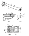
- Figure 1 shows a graphical representation dental instrument with a handle body 1 on the One end is a head part 2, in which in a known For example, a rotor 3 (tube) which can be driven with compressed air for the Drive of a rotatable tool 4 arranged is.
- the other end of the instrument has a fitting 5 for the connection of a supply hose, not shown through which the media air and water to the instrument be introduced.
- Corresponding ones are in the instrument itself Lines or channels provided.
- the line labeled 6 is intended for the supply of spray water and the line labeled 7 for the supply of spray air apply.
- the two media spray air and spray water are combined in one located in the area of the head part 2, not shown here Mixing chamber mixed into spray, the one marked with 8 Place aimed at the tip of the tool 4 exit.
- Figure 2 shows a section of the instrument in one Longitudinal representation, it is assumed that the handle body 1 receiving the lines or channels Base body 9 includes an outer sleeve 10 is removably placed, which is not shown in Figure 2 is.
- the base body 9 contains a changeover valve 11 with which the The proportion of spray air varies and due to the higher air pressure hence the water content of the spray at the point of exit 8 can be increased or reduced within certain limits can.
- the changeover valve 11 comprises a line duct of the line 7 radially penetrating closing body 12 and an actuator 13 for adjusting the closing body.
- the closing body 12 is as a rotary flap and the control element 13 as Set screw trained.
- Closing bodies are advantageous 12 and actuator 13 made in one piece and in a radial bore in the base body 9 is used.
- the control element 13 is provided with a bearing pin 14, which engages in a corresponding hole in the base body 9.
- the actuating element 13 has a screw slot 15 for switching of the valve from a position with closed to to a position with a fully open cross-section, being a stepless design of the closing body Switching is achieved.
- a simple version one Two-point switching from a minimum to a maximum Flow rate can be provided.
- the closing body 12 is provided with a small bore 16 the passage in the closed position ( Figure 4) allowed a minimum amount of cooling air. In this Valve position occurs at the exit point 8 'rich' spray with very high water content while in the open Position ( Figures 2 and 3) the water content is normal.
- the screw slot 15 serves on the one hand to adjust the Closing body 12 and on the other hand in connection with the outside on Markings 17 (FIG. 5) as a setting orientation, with the the operating position of the valve is recognizable.
- the markings 17 can be designed individually and be executed differently.
- Figure 5 there are two conceivable examples represented in the form of symbols, a Drop and a sickle shape. Labeling is also an alternative or color code conceivable.
Landscapes
- Health & Medical Sciences (AREA)
- Oral & Maxillofacial Surgery (AREA)
- Dentistry (AREA)
- Epidemiology (AREA)
- Life Sciences & Earth Sciences (AREA)
- Animal Behavior & Ethology (AREA)
- General Health & Medical Sciences (AREA)
- Public Health (AREA)
- Veterinary Medicine (AREA)
- Dental Tools And Instruments Or Auxiliary Dental Instruments (AREA)
Abstract
Description
- Figur 1
- ein zahnärztliches Instrument in einer Übersichtdarstellung
- Figur 2
- einen Ausschnitt aus einem Teil des Instruments nach Figur 1 mit dem erfindungsgemäßen Umschaltventil
- Figur 3
- eine Detaildarstellung der Anordnung mit dem Umschaltventils in einer ersten Schaltstellung
- Figur 4
- eine Detaildarstellung der Anordnung mit dem Umschaltventils in einer zweiten Schaltstellung
- Figur 5
- eine Draufsicht auf das Umschaltventil
- 1
- = Griffkörper
- 2
- = Kopfteil
- 3 =
- Antriebsrotor
- 4 =
- Werkzeug
- 5 =
- Anschlußarmatur
- 6 =
- Wasserzufuhrleitung
- 7 =
- Luftzufuhrleitung
- 8 =
- Sprayaustrittsstelle
- 9 =
- Grundkörper
- 10 =
- äußere Hülse
- 11 =
- Unschaltventil
- 12 =
- Schließkörper (Drehklappe)
- 13 =
- Stellelement (Stellschraube)
- 14 =
- Lagerzapfen
- 15 =
- Schraubschlitz
- 16 =
- Bohrung
- 17 =
- Markierung
Claims (6)
- Zahnärztliches Instrument in welchem zur Kühlung der Präparationsstelle Leitungskanäle (6, 7) zur Zufuhr einerseits von Kühlwasser und andererseits von Kühlluft vorhanden sind, und welches ein von Hand betätigbares Ventil zur Änderung des Durchflusses zumindest der Kühlluft enthält, dadurch gekennzeichnet, daß in den Leitungskanal (7) der Kühlluft ein Umschaltventil (11) mit einem als Drehklappe ausgebildeten Schließkörper (12) eingesetzt ist, mit dem der Durchflußquerschnitt des Kühlluftkanals (7) von einer Stellung mit geschlossenem bis zu einer Stellung mit voll geöffnetem Querschnitt verändert werden kann, wobei der Schließkörper (12) eine Öffnung (16) enthält, die in der geschlossenen Stellung den Durchfluß einer minimalen Menge an Kühlluft gestattet.
- Zahnärztliches Instrument nach Anspruch 1, d adurch gekennzeichnet, daß der Schließkörper (12) so gestaltet ist, dass bei dessen Verstellung der Durchflußquerschnitt kontinuierlich verändert wird.
- Zahnärztliches Instrument nach Anspruch 1 oder 2, dadurch gekennzeichnet, daß der Schließkörper (12) mit einem als Stellschraube ausgebildeten Stellelement (13) verbunden ist das an seiner Oberseite ein Einstellorientierungsmittel (15) aufweist, welches mit Markierungen (17) an Teilen des Instruments (9) korrespondiert.
- Zahnärztliches Instrument nach Anspruch 3, d adurch gekennzeichnet, daß als Einstellorientierungsmittel der Schraubschlitz (15) der Stellschraube des Stellelements (13) vorgesehen ist.
- Zahnärztliches Instrument nach einem der Ansprüche 1 bis 4, dadurch gekennzeichnet, daß Schließkörper (12) und Stellelement (13) einstückig ausgebildet sind.
- Zahnärztliches Instrument nach einem der Ansprüche 1 bis 5, dadurch gekennzeichnet, daß das Umschaltventil (11) den Kühlluftkanal (7) radial durchdringend in einem Grundkörper (9) des Instruments angeordnet ist, den eine abnehmbar gehalterte Außenhülse (10) übergreift.
Applications Claiming Priority (2)
| Application Number | Priority Date | Filing Date | Title |
|---|---|---|---|
| DE10025013A DE10025013C2 (de) | 2000-05-22 | 2000-05-22 | Zahnärztliches Instrument mit Mitteln zur Kühlung der Präparationsstelle |
| DE10025013 | 2000-05-22 |
Publications (3)
| Publication Number | Publication Date |
|---|---|
| EP1157669A2 true EP1157669A2 (de) | 2001-11-28 |
| EP1157669A3 EP1157669A3 (de) | 2003-02-05 |
| EP1157669B1 EP1157669B1 (de) | 2005-08-03 |
Family
ID=7642927
Family Applications (1)
| Application Number | Title | Priority Date | Filing Date |
|---|---|---|---|
| EP01112435A Expired - Lifetime EP1157669B1 (de) | 2000-05-22 | 2001-05-22 | Zahnärztliches Instrument mit Mitteln zur Kühlung der Präparationsstelle |
Country Status (3)
| Country | Link |
|---|---|
| EP (1) | EP1157669B1 (de) |
| AT (1) | ATE300918T1 (de) |
| DE (2) | DE10025013C2 (de) |
Citations (2)
| Publication number | Priority date | Publication date | Assignee | Title |
|---|---|---|---|---|
| DE1918979A1 (de) | 1969-04-15 | 1970-10-29 | Siemens Ag | Zahnaerztliches Bohrhandstueck |
| DE2207240A1 (de) | 1972-02-16 | 1973-08-23 | Siemens Ag | Absperr- und einstellventil fuer zahnaerztliche handstuecke |
Family Cites Families (4)
| Publication number | Priority date | Publication date | Assignee | Title |
|---|---|---|---|---|
| US1596632A (en) * | 1925-02-03 | 1926-08-17 | Seidl Leo | Dental handpiece spray |
| GB853639A (en) * | 1958-04-21 | 1960-11-09 | Atlas Copco Ab | Improvements in fluid dispensing apparatuses for dental engines |
| DE2930853C2 (de) * | 1979-07-30 | 1986-10-02 | Siemens AG, 1000 Berlin und 8000 München | Zahnärztliches Handstück mit einem Ventil zur Steuerung des Durchflusses eines strömenden Mediums |
| DE3302584A1 (de) * | 1983-01-26 | 1984-07-26 | Kaltenbach & Voigt Gmbh & Co, 7950 Biberach | Zahnaerztliches handstueck |
-
2000
- 2000-05-22 DE DE10025013A patent/DE10025013C2/de not_active Expired - Fee Related
-
2001
- 2001-05-22 DE DE50106943T patent/DE50106943D1/de not_active Expired - Lifetime
- 2001-05-22 AT AT01112435T patent/ATE300918T1/de active
- 2001-05-22 EP EP01112435A patent/EP1157669B1/de not_active Expired - Lifetime
Patent Citations (2)
| Publication number | Priority date | Publication date | Assignee | Title |
|---|---|---|---|---|
| DE1918979A1 (de) | 1969-04-15 | 1970-10-29 | Siemens Ag | Zahnaerztliches Bohrhandstueck |
| DE2207240A1 (de) | 1972-02-16 | 1973-08-23 | Siemens Ag | Absperr- und einstellventil fuer zahnaerztliche handstuecke |
Also Published As
| Publication number | Publication date |
|---|---|
| DE10025013C2 (de) | 2002-12-12 |
| EP1157669A3 (de) | 2003-02-05 |
| ATE300918T1 (de) | 2005-08-15 |
| DE50106943D1 (de) | 2005-09-08 |
| DE10025013A1 (de) | 2001-12-06 |
| EP1157669B1 (de) | 2005-08-03 |
Similar Documents
| Publication | Publication Date | Title |
|---|---|---|
| DE3202040C2 (de) | ||
| CH623904A5 (de) | ||
| WO2011003493A1 (de) | Farbspritzpistole | |
| EP0356690A1 (de) | Brennstoffbefeuerter Wärmeerzeuger | |
| DE69102015T2 (de) | Wassermischventil mit getrennten Betätigungen für die Ausgabe zweier Wasserarten. | |
| DE2207240A1 (de) | Absperr- und einstellventil fuer zahnaerztliche handstuecke | |
| DE60012740T2 (de) | Sprühkopf | |
| DE68904757T2 (de) | Kugelventil. | |
| DE8225789U1 (de) | Vorrichtung zum Steuern eines pneumatischen Geräts | |
| DE2740205A1 (de) | Mischventil fuer das sanitaerfach | |
| DE2945432C1 (de) | Sicherheitsbrenner zum Pulverflammspritzen | |
| EP1157669B1 (de) | Zahnärztliches Instrument mit Mitteln zur Kühlung der Präparationsstelle | |
| DE19629137A1 (de) | Steuereinrichtung für ein Fluid, wie Wasser | |
| EP0096005A1 (de) | Einhebel-Mischarmatur zur Steuerung der Abgabemenge und des Mischverhältnisses von warmem und kaltem Wasser | |
| EP0210472B1 (de) | Vorrichtung zur Regelung der Menge und/oder des Mischungsverhältnisses eines Brenngas-Luft-Gemisches | |
| DE2852576C2 (de) | Dental-Handstück | |
| DE3635698A1 (de) | Flammspritzbrenner zur herstellung von oberflaechenschichten auf werkstuecken | |
| DE3908009A1 (de) | Sanitaerventil | |
| EP0927580A1 (de) | Handbrause | |
| DE19812128A1 (de) | Vorrichtung zum Regeln von Durchflußmengen strömender Medien und Verfahren zur Minimalmengen-Kühlschmiervorrichtung | |
| EP3217103A1 (de) | Ventileinsatz für ein heizkörperventil und heizkörper mit heizkörperventil | |
| DE69227256T2 (de) | Mengen-und temperaturbegrenzungsvorrichtung fuer ein mischventil | |
| DE3204031C2 (de) | Steuerventil eines Brenners für flüssiges oder gasförmiges Medium | |
| DE2743589A1 (de) | Spritzpistole fuer zwei-komponenten- kunststoff | |
| DE102004019270B4 (de) | Handbrause |
Legal Events
| Date | Code | Title | Description |
|---|---|---|---|
| PUAI | Public reference made under article 153(3) epc to a published international application that has entered the european phase |
Free format text: ORIGINAL CODE: 0009012 |
|
| AK | Designated contracting states |
Kind code of ref document: A2 Designated state(s): AT BE CH CY DE DK ES FI FR GB GR IE IT LI LU MC NL PT SE TR |
|
| AX | Request for extension of the european patent |
Free format text: AL;LT;LV;MK;RO;SI |
|
| PUAL | Search report despatched |
Free format text: ORIGINAL CODE: 0009013 |
|
| AK | Designated contracting states |
Designated state(s): AT BE CH CY DE DK ES FI FR GB GR IE IT LI LU MC NL PT SE TR |
|
| AX | Request for extension of the european patent |
Extension state: AL LT LV MK RO SI |
|
| 17P | Request for examination filed |
Effective date: 20030614 |
|
| AKX | Designation fees paid |
Designated state(s): AT BE CH CY DE DK ES FI FR GB GR IE IT LI LU MC NL PT SE TR |
|
| GRAP | Despatch of communication of intention to grant a patent |
Free format text: ORIGINAL CODE: EPIDOSNIGR1 |
|
| GRAS | Grant fee paid |
Free format text: ORIGINAL CODE: EPIDOSNIGR3 |
|
| GRAA | (expected) grant |
Free format text: ORIGINAL CODE: 0009210 |
|
| AK | Designated contracting states |
Kind code of ref document: B1 Designated state(s): AT BE CH CY DE DK ES FI FR GB GR IE IT LI LU MC NL PT SE TR |
|
| PG25 | Lapsed in a contracting state [announced via postgrant information from national office to epo] |
Ref country code: TR Free format text: LAPSE BECAUSE OF FAILURE TO SUBMIT A TRANSLATION OF THE DESCRIPTION OR TO PAY THE FEE WITHIN THE PRESCRIBED TIME-LIMIT Effective date: 20050803 Ref country code: GB Free format text: LAPSE BECAUSE OF FAILURE TO SUBMIT A TRANSLATION OF THE DESCRIPTION OR TO PAY THE FEE WITHIN THE PRESCRIBED TIME-LIMIT Effective date: 20050803 Ref country code: NL Free format text: LAPSE BECAUSE OF FAILURE TO SUBMIT A TRANSLATION OF THE DESCRIPTION OR TO PAY THE FEE WITHIN THE PRESCRIBED TIME-LIMIT Effective date: 20050803 Ref country code: IE Free format text: LAPSE BECAUSE OF FAILURE TO SUBMIT A TRANSLATION OF THE DESCRIPTION OR TO PAY THE FEE WITHIN THE PRESCRIBED TIME-LIMIT Effective date: 20050803 Ref country code: FI Free format text: LAPSE BECAUSE OF FAILURE TO SUBMIT A TRANSLATION OF THE DESCRIPTION OR TO PAY THE FEE WITHIN THE PRESCRIBED TIME-LIMIT Effective date: 20050803 |
|
| REG | Reference to a national code |
Ref country code: GB Ref legal event code: FG4D Free format text: NOT ENGLISH |
|
| REG | Reference to a national code |
Ref country code: CH Ref legal event code: EP |
|
| REG | Reference to a national code |
Ref country code: IE Ref legal event code: FG4D Free format text: LANGUAGE OF EP DOCUMENT: GERMAN |
|
| REF | Corresponds to: |
Ref document number: 50106943 Country of ref document: DE Date of ref document: 20050908 Kind code of ref document: P |
|
| REG | Reference to a national code |
Ref country code: CH Ref legal event code: NV Representative=s name: WILLIAM BLANC & CIE CONSEILS EN PROPRIETE INDUSTRI |
|
| PG25 | Lapsed in a contracting state [announced via postgrant information from national office to epo] |
Ref country code: SE Free format text: LAPSE BECAUSE OF FAILURE TO SUBMIT A TRANSLATION OF THE DESCRIPTION OR TO PAY THE FEE WITHIN THE PRESCRIBED TIME-LIMIT Effective date: 20051103 Ref country code: GR Free format text: LAPSE BECAUSE OF FAILURE TO SUBMIT A TRANSLATION OF THE DESCRIPTION OR TO PAY THE FEE WITHIN THE PRESCRIBED TIME-LIMIT Effective date: 20051103 Ref country code: DK Free format text: LAPSE BECAUSE OF FAILURE TO SUBMIT A TRANSLATION OF THE DESCRIPTION OR TO PAY THE FEE WITHIN THE PRESCRIBED TIME-LIMIT Effective date: 20051103 |
|
| PG25 | Lapsed in a contracting state [announced via postgrant information from national office to epo] |
Ref country code: ES Free format text: LAPSE BECAUSE OF FAILURE TO SUBMIT A TRANSLATION OF THE DESCRIPTION OR TO PAY THE FEE WITHIN THE PRESCRIBED TIME-LIMIT Effective date: 20051114 |
|
| PG25 | Lapsed in a contracting state [announced via postgrant information from national office to epo] |
Ref country code: PT Free format text: LAPSE BECAUSE OF FAILURE TO SUBMIT A TRANSLATION OF THE DESCRIPTION OR TO PAY THE FEE WITHIN THE PRESCRIBED TIME-LIMIT Effective date: 20060103 |
|
| NLV1 | Nl: lapsed or annulled due to failure to fulfill the requirements of art. 29p and 29m of the patents act | ||
| GBV | Gb: ep patent (uk) treated as always having been void in accordance with gb section 77(7)/1977 [no translation filed] |
Effective date: 20050803 |
|
| REG | Reference to a national code |
Ref country code: IE Ref legal event code: FD4D |
|
| PG25 | Lapsed in a contracting state [announced via postgrant information from national office to epo] |
Ref country code: BE Free format text: LAPSE BECAUSE OF NON-PAYMENT OF DUE FEES Effective date: 20060531 Ref country code: MC Free format text: LAPSE BECAUSE OF NON-PAYMENT OF DUE FEES Effective date: 20060531 |
|
| PLBE | No opposition filed within time limit |
Free format text: ORIGINAL CODE: 0009261 |
|
| STAA | Information on the status of an ep patent application or granted ep patent |
Free format text: STATUS: NO OPPOSITION FILED WITHIN TIME LIMIT |
|
| 26N | No opposition filed |
Effective date: 20060504 |
|
| EN | Fr: translation not filed | ||
| PG25 | Lapsed in a contracting state [announced via postgrant information from national office to epo] |
Ref country code: FR Free format text: LAPSE BECAUSE OF FAILURE TO SUBMIT A TRANSLATION OF THE DESCRIPTION OR TO PAY THE FEE WITHIN THE PRESCRIBED TIME-LIMIT Effective date: 20060929 |
|
| BERE | Be: lapsed |
Owner name: SIRONA DENTAL SYSTEMS G.M.B.H. Effective date: 20060531 |
|
| PG25 | Lapsed in a contracting state [announced via postgrant information from national office to epo] |
Ref country code: LU Free format text: LAPSE BECAUSE OF NON-PAYMENT OF DUE FEES Effective date: 20060522 |
|
| PG25 | Lapsed in a contracting state [announced via postgrant information from national office to epo] |
Ref country code: FR Free format text: LAPSE BECAUSE OF FAILURE TO SUBMIT A TRANSLATION OF THE DESCRIPTION OR TO PAY THE FEE WITHIN THE PRESCRIBED TIME-LIMIT Effective date: 20050803 Ref country code: CY Free format text: LAPSE BECAUSE OF FAILURE TO SUBMIT A TRANSLATION OF THE DESCRIPTION OR TO PAY THE FEE WITHIN THE PRESCRIBED TIME-LIMIT Effective date: 20050803 |
|
| REG | Reference to a national code |
Ref country code: CH Ref legal event code: PFA Owner name: SIRONA DENTAL SYSTEMS GMBH Free format text: SIRONA DENTAL SYSTEMS GMBH#FABRIKSTRASSE 31#64625 BENSHEIM (DE) -TRANSFER TO- SIRONA DENTAL SYSTEMS GMBH#FABRIKSTRASSE 31#64625 BENSHEIM (DE) |
|
| REG | Reference to a national code |
Ref country code: CH Ref legal event code: PCAR Free format text: NOVAGRAAF SWITZERLAND SA;CHEMIN DE L'ECHO 3;1213 ONEX (CH) |
|
| PGFP | Annual fee paid to national office [announced via postgrant information from national office to epo] |
Ref country code: CH Payment date: 20120530 Year of fee payment: 12 Ref country code: DE Payment date: 20120625 Year of fee payment: 12 |
|
| PGFP | Annual fee paid to national office [announced via postgrant information from national office to epo] |
Ref country code: IT Payment date: 20120522 Year of fee payment: 12 |
|
| PGFP | Annual fee paid to national office [announced via postgrant information from national office to epo] |
Ref country code: AT Payment date: 20120523 Year of fee payment: 12 |
|
| REG | Reference to a national code |
Ref country code: CH Ref legal event code: PL |
|
| REG | Reference to a national code |
Ref country code: AT Ref legal event code: MM01 Ref document number: 300918 Country of ref document: AT Kind code of ref document: T Effective date: 20130531 |
|
| PG25 | Lapsed in a contracting state [announced via postgrant information from national office to epo] |
Ref country code: LI Free format text: LAPSE BECAUSE OF NON-PAYMENT OF DUE FEES Effective date: 20130531 Ref country code: CH Free format text: LAPSE BECAUSE OF NON-PAYMENT OF DUE FEES Effective date: 20130531 Ref country code: AT Free format text: LAPSE BECAUSE OF NON-PAYMENT OF DUE FEES Effective date: 20130531 Ref country code: DE Free format text: LAPSE BECAUSE OF NON-PAYMENT OF DUE FEES Effective date: 20131203 |
|
| PG25 | Lapsed in a contracting state [announced via postgrant information from national office to epo] |
Ref country code: IT Free format text: LAPSE BECAUSE OF NON-PAYMENT OF DUE FEES Effective date: 20130522 |
|
| REG | Reference to a national code |
Ref country code: DE Ref legal event code: R119 Ref document number: 50106943 Country of ref document: DE Effective date: 20131203 |