EP1156701A2 - Elektroakustischer Wandler mit kleinen Abmessungen - Google Patents
Elektroakustischer Wandler mit kleinen Abmessungen Download PDFInfo
- Publication number
- EP1156701A2 EP1156701A2 EP01890099A EP01890099A EP1156701A2 EP 1156701 A2 EP1156701 A2 EP 1156701A2 EP 01890099 A EP01890099 A EP 01890099A EP 01890099 A EP01890099 A EP 01890099A EP 1156701 A2 EP1156701 A2 EP 1156701A2
- Authority
- EP
- European Patent Office
- Prior art keywords
- housing
- pot
- electroacoustic transducer
- component
- yoke
- Prior art date
- Legal status (The legal status is an assumption and is not a legal conclusion. Google has not performed a legal analysis and makes no representation as to the accuracy of the status listed.)
- Granted
Links
Images


Classifications
-
- H—ELECTRICITY
- H04—ELECTRIC COMMUNICATION TECHNIQUE
- H04R—LOUDSPEAKERS, MICROPHONES, GRAMOPHONE PICK-UPS OR LIKE ACOUSTIC ELECTROMECHANICAL TRANSDUCERS; ELECTRIC HEARING AIDS; PUBLIC ADDRESS SYSTEMS
- H04R9/00—Transducers of moving-coil, moving-strip, or moving-wire type
Definitions
- Classic electroacoustic transducers that work on the electrodynamic principle, consist essentially of a pot-like housing, open on the front, into which a magnet system is used in the front, which consists of the actual magnet and a there is a multi-part yoke, the yoke having an annular air gap on the front trains.
- a membrane attached to the front of the magnet system has one Voice coil that protrudes into the air gap of the yoke and there in the axial direction can swing.
- the individual yoke parts are mostly: a pot-like, bottom side arranged part, in the center of which the magnet is glued and a circular Front part, the outer circumference of which forms the inner circumference of the air gap.
- the method according to the invention is for small size electroacoustic transducers Particularly suitable, since only with such miniaturized transducers by Copper plating and nickel plating achievable metal cross sections are sufficient to Ladder can be used.
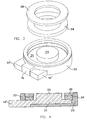
- contacts 4 for the supply wires for the voice coil (not shown) of the membrane are arranged on a projection 3 of the housing 2.
- These contacts 4 usually consist of sheet metal as stamped or bent parts, which are to be fitted to the projection 3 with a precise fit and not wobbling. These parts must therefore be fixed by gluing, using an adhesive drop with a volume of about 0.3 mm 3 .
- This dosage and correct placement encounter major problems in automatic series production and require human monitoring and support.
- a component 11 is produced in an injection mold essentially has the shape of the pot-like yoke part 1, but on the one Projection 3 corresponding projection 13 is integrally formed with.
- This component consists of a metallizable plastic and it is when in the injection mold is solidified accordingly, this is not removed, but only the top of the Injection mold is replaced by another upper part and this then becomes pot-like Component 11 in essential areas surrounded by a plastic that is not is metallizable and finally has an outer shape, at least in essentially the shape of the housing 2 of conventional electroacoustic transducers corresponds.
- This outer part 12 preferably has at one point, as shown in FIG. 2, a recess or notch 16 so that an area 14 'of the projection 13 over a free surface lying in the area of the notch 16 with the inner area of the Pot-like component 11 is connected.
- the further processing of the semi-finished electro-acoustic transducer thus produced takes place in the usual way: the magnet becomes in the center of the pot-like component 11 including the disc-shaped yoke part already glued to it, whereby by Appropriate guidance or teaching ensures sufficient centricity. It then the membrane, if necessary with a mounting or retaining ring on Housing part 12 attached, the voice coil mounted on the diaphragm centrally in the air gap comes to rest.
- the voice coil supply wires are in the Area of the membranes fastening from the inside of the then closed transducer guided and each with one of the two contacts 14 ', 14 "mechanically and electrically conductively connected, for example by friction welding or ultrasonic welding.
- FIG. 3 and 4 show a variant possible by the measures according to the invention with a slightly different construction of the transducer than that obtained according to FIG. 2: It will thereby how the exploded in the axial direction in the manner of an explosion sketch
- the illustration shows a body part 21 with a correspondingly partially galvanized surface extrusion-coated with a housing part 22, the material of the housing part 22 not is galvanizable.
- the body part 21 has integrally formed a central elevation represents the inner yoke part 23.
- FIGS. 5 and 6 Another variant is shown in FIGS. 5 and 6; one (or several appropriately arranged) used radially magnetized magnet. 5 shows this the previous structure of such electroacoustic transducers according to the state of the Technology and Fig. 6 shows a variant according to the invention.
- FIG. 5 there is an electroacoustic transducer with radial magnetized magnets made of several plate-shaped magnets that are normal to the Platelet main plane are magnetized, these platelets along the lateral surface of a regular polygon.
- the cause of using this The arrangement is that it is extremely difficult to use radial magnets with radial To produce magnetization, so that you are quasi-ring-shaped Arrangement helps.
- FIG. 6 A partially galvanic Metallized outer housing 42 and an at least partially galvanized yoke part 41 are provided with correspondingly flat surfaces 43, 45 during injection molding, between which the plate-shaped magnets 44 lie in the assembled state come.
- the surfaces 43, 45 and the adjacent areas (Fig. 6 up), the finally leave the air gap between them are galvanized with metal coated and serve as a yoke for the magnet system.
- FIG. 6 A centrally symmetrical transducer body has been shown in Fig. 6, but it is of course also possible and advantageous here, the contacts, as with the 2 and 3, to be trained at the same time and also galvanized, what can happen analogously to the formation of Fig. 2 or 3 and here no closer Explanation needs more.
- annular groove is indicated on the upper outer edge of the housing part 42, the serves to receive a fastening ring for a membrane, this ring groove can of course, be designed differently, the attachment of the membrane to one Housing part is part of the state of the art, due to the integral manufacture of Injection molding can achieve extremely high centricity without this being otherwise would cause necessary costs.
Landscapes
- Physics & Mathematics (AREA)
- Engineering & Computer Science (AREA)
- Acoustics & Sound (AREA)
- Signal Processing (AREA)
- Audible-Bandwidth Dynamoelectric Transducers Other Than Pickups (AREA)
- Transducers For Ultrasonic Waves (AREA)
- Details Of Audible-Bandwidth Transducers (AREA)
- Piezo-Electric Transducers For Audible Bands (AREA)
- Diaphragms For Electromechanical Transducers (AREA)
Abstract
Description
Claims (4)
- Elektroakustischer Wandler mit kleinen Abmessungen, insbesondere mit einem Gehäuse mit einem Außendurchmesser von 15 mm und kleiner, dadurch gekennzeichnet, daß er einen topfartigen Topfbauteil (11,21,31) aus einem metallisierbaren Kunststoff aufweist, der von einem Gehäuseform aufweisenden Gehäusebauteil (12,22,32) aus einem nicht metallisierbaren Kunststoff umgossen ist, und daß zumindest die innere Oberfläche des Topfbauteiles (11,21,31) mit einem Metallüberzug versehen ist.
- Elektroakustischer Wandler nach Anspruch 1, dadurch gekennzeichnet, daß der Topfbauteil (11,21,31) zumindest einen radial abstehenden Vorsprung (13) aufweist, und daß zumindest ein Teil der Oberfläche (14', 14") des radial abstehenden Vorsprunges (13) mit einem Metallüberzug versehen ist.
- Elektroakustischer Wandler mit kleinen Abmessungen, insbesondere mit einem Gehäuse mit einem Außendurchmesser von 15 mm und kleiner, mit radial magnetisierten Magnetplättchen (44), dadurch gekennzeichnet, daß er einen Jochteil (41) aufweist, der im Bereich seiner äußeren Mantelfläche (43) metallisiert ist und einen ringförmigen, vom Jochteil getrennten Gehäusebauteil (42), der im Bereich seiner inneren Mantelfläche (45) metallisiert ist, und daß die Magnetplättchen (44) zwischen den metallisierten Mantelflächen (43, 45) angeordnet sind.
- Elektroakustischer Wandler nach Anspruch 3, dadurch gekennzeichnet, daß der Jochteil (41) zumindest einen radial abstehenden Vorsprung aufweist, und daß zumindest ein Teil der Oberfläche des radial abstehenden Vorsprunges mit einem Metallüberzug versehen ist.
Priority Applications (1)
| Application Number | Priority Date | Filing Date | Title |
|---|---|---|---|
| AT01890099T ATE405128T1 (de) | 2000-05-15 | 2001-03-28 | Elektroakustischer wandler mit kleinen abmessungen |
Applications Claiming Priority (2)
| Application Number | Priority Date | Filing Date | Title |
|---|---|---|---|
| AT8422000 | 2000-05-15 | ||
| AT0084200A AT411559B (de) | 2000-05-15 | 2000-05-15 | Elektroakustischer wandler mit kleinen abmessungen |
Publications (3)
| Publication Number | Publication Date |
|---|---|
| EP1156701A2 true EP1156701A2 (de) | 2001-11-21 |
| EP1156701A3 EP1156701A3 (de) | 2007-04-18 |
| EP1156701B1 EP1156701B1 (de) | 2008-08-13 |
Family
ID=3682054
Family Applications (1)
| Application Number | Title | Priority Date | Filing Date |
|---|---|---|---|
| EP01890099A Expired - Lifetime EP1156701B1 (de) | 2000-05-15 | 2001-03-28 | Elektroakustischer Wandler mit kleinen Abmessungen |
Country Status (7)
| Country | Link |
|---|---|
| US (2) | US6668066B2 (de) |
| EP (1) | EP1156701B1 (de) |
| JP (1) | JP2001326992A (de) |
| CN (1) | CN1232091C (de) |
| AT (2) | AT411559B (de) |
| DE (1) | DE50114205D1 (de) |
| DK (1) | DK1156701T3 (de) |
Families Citing this family (8)
| Publication number | Priority date | Publication date | Assignee | Title |
|---|---|---|---|---|
| JP2003289596A (ja) * | 2002-03-27 | 2003-10-10 | Citizen Electronics Co Ltd | スピーカ及びその製造方法 |
| KR20020057897A (ko) * | 2002-05-28 | 2002-07-12 | 전창만 | 다기능 전자음향변환기의 구조 |
| EP1515582B1 (de) * | 2003-09-11 | 2006-01-11 | AKG Acoustics GmbH | Dynamischer elektroakustischer Wandler, insbesondere kleiner Lautsprecher |
| EP1694094A1 (de) * | 2005-02-18 | 2006-08-23 | AKG Acoustics GmbH | Membran für einen dynamischen Wandler |
| FR2919486B1 (fr) * | 2007-07-31 | 2009-10-02 | Captomed Entpr Unipersonnelle | Capteur de pression auto-etalonnable. |
| DE102009038593A1 (de) * | 2009-08-26 | 2011-03-03 | Beyerdynamic Gmbh & Co. Kg | Schallwandler-Magnetsystem |
| ITPD20110191A1 (it) * | 2011-06-13 | 2012-12-14 | Maurizio Servadio | Trasduttore elettromeccanico/elettroacustico sottile |
| CN112134018B (zh) * | 2020-10-26 | 2024-11-26 | 广东华旃电子有限公司 | 汽车天线屏蔽组件及其制作方法 |
Family Cites Families (6)
| Publication number | Priority date | Publication date | Assignee | Title |
|---|---|---|---|---|
| AT366862B (de) * | 1980-07-28 | 1982-05-10 | Akg Akustische Kino Geraete | Elektroakustischer wandler nach dem zweiwegprinzip |
| US6151402A (en) * | 1995-09-02 | 2000-11-21 | New Transducers Limited | Vibration transducers |
| US6047077A (en) * | 1998-09-29 | 2000-04-04 | Larsen; John T. | Bipolar speaker |
| JP3035704B1 (ja) * | 1998-10-28 | 2000-04-24 | 株式会社アクーヴ・ラボ | 電気−機械振動変換器 |
| JP4276315B2 (ja) * | 1998-11-17 | 2009-06-10 | シチズン電子株式会社 | 電磁型発音体 |
| JP2002058095A (ja) * | 2000-08-11 | 2002-02-22 | Star Micronics Co Ltd | 電磁音響変換器 |
-
2000
- 2000-05-15 AT AT0084200A patent/AT411559B/de not_active IP Right Cessation
-
2001
- 2001-03-28 AT AT01890099T patent/ATE405128T1/de not_active IP Right Cessation
- 2001-03-28 DE DE50114205T patent/DE50114205D1/de not_active Expired - Fee Related
- 2001-03-28 EP EP01890099A patent/EP1156701B1/de not_active Expired - Lifetime
- 2001-03-28 DK DK01890099T patent/DK1156701T3/da active
- 2001-05-09 US US09/852,444 patent/US6668066B2/en not_active Expired - Fee Related
- 2001-05-11 CN CN01117914.7A patent/CN1232091C/zh not_active Expired - Fee Related
- 2001-05-14 JP JP2001143105A patent/JP2001326992A/ja not_active Withdrawn
-
2003
- 2003-10-02 US US10/678,453 patent/US7245738B2/en not_active Expired - Fee Related
Also Published As
| Publication number | Publication date |
|---|---|
| US7245738B2 (en) | 2007-07-17 |
| JP2001326992A (ja) | 2001-11-22 |
| US20010040972A1 (en) | 2001-11-15 |
| US20040066950A1 (en) | 2004-04-08 |
| EP1156701A3 (de) | 2007-04-18 |
| EP1156701B1 (de) | 2008-08-13 |
| US6668066B2 (en) | 2003-12-23 |
| ATE405128T1 (de) | 2008-08-15 |
| AT411559B (de) | 2004-02-25 |
| ATA8422000A (de) | 2003-07-15 |
| DK1156701T3 (da) | 2008-12-15 |
| DE50114205D1 (de) | 2008-09-25 |
| CN1232091C (zh) | 2005-12-14 |
| CN1327335A (zh) | 2001-12-19 |
Similar Documents
| Publication | Publication Date | Title |
|---|---|---|
| DE69106432T2 (de) | Piezoelektrischer Wandler. | |
| DE60221857T2 (de) | Akustischen Miniwandler | |
| DE2828148C2 (de) | Biegeanordnung | |
| DE68919100T2 (de) | Piezoelektrischer Summer und Verfahren zu dessen Herstellung. | |
| DE3128686C2 (de) | ||
| DE69934119T2 (de) | Schall-/ schwingungsgenerator | |
| DE3211072C3 (de) | Elektret-Richtmikrofon | |
| DE69423128T2 (de) | Elektroakustischer Wandler | |
| EP0480160A2 (de) | Kalotten-Hochton-Lautsprecher | |
| DE69211512T2 (de) | Ausgewogene Armaturwandler mit transversalem Zwischenraum | |
| DE69320306T2 (de) | Elektroakustischer Wandler | |
| DE29711234U1 (de) | Aufnahmevorrichtung für ein Mikrofon | |
| AT411559B (de) | Elektroakustischer wandler mit kleinen abmessungen | |
| EP0615398B1 (de) | Elektroakustischer Wandler mit einer Maske | |
| DE19715365C2 (de) | Kondensatormikrofon | |
| DE2909477C2 (de) | Anordnung zum Umwandeln akustischer Schwingungen in elektrische Schwingungen und umgekehrt, mit mindestens einem Kondensatorelektretelement, das an eine elektronische Schaltungsanordnung angeschlossen ist | |
| DE102006006043A1 (de) | Lautsprecher und Verfahren zur Herstellung des Lautsprechers | |
| DE69917148T2 (de) | Elektroakustischer wandler und membrane für elektroakustischen wandler | |
| DE1224366B (de) | Elektroakustischer Wandler und Vorrichtung zu seiner Herstellung | |
| EP1762117B1 (de) | Kondensatormikrofon | |
| AT414196B (de) | Magnetsystem eines schallwandlers | |
| DE102017119865A1 (de) | Elektrodynamischer Schallwandler und Verfahren zum Herstellen eines elektrodynamischen Schallwandlers | |
| DE3923189A1 (de) | Lautsprecher | |
| DE2909065A1 (de) | Droehnfreie mikrophonkombination mit zwei mikrophonelementen | |
| DE2936965C2 (de) | Permanentdynamische elektroakustische Wandlerkapsel |
Legal Events
| Date | Code | Title | Description |
|---|---|---|---|
| PUAI | Public reference made under article 153(3) epc to a published international application that has entered the european phase |
Free format text: ORIGINAL CODE: 0009012 |
|
| AK | Designated contracting states |
Kind code of ref document: A2 Designated state(s): AT BE CH CY DE DK ES FI FR GB GR IE IT LI LU MC NL PT SE TR |
|
| AX | Request for extension of the european patent |
Free format text: AL;LT;LV;MK;RO;SI |
|
| PUAL | Search report despatched |
Free format text: ORIGINAL CODE: 0009013 |
|
| AK | Designated contracting states |
Kind code of ref document: A3 Designated state(s): AT BE CH CY DE DK ES FI FR GB GR IE IT LI LU MC NL PT SE TR |
|
| AX | Request for extension of the european patent |
Extension state: AL LT LV MK RO SI |
|
| 17P | Request for examination filed |
Effective date: 20071018 |
|
| AKX | Designation fees paid |
Designated state(s): AT BE CH CY DE DK ES FI FR GB GR IE IT LI LU MC NL PT SE TR |
|
| GRAP | Despatch of communication of intention to grant a patent |
Free format text: ORIGINAL CODE: EPIDOSNIGR1 |
|
| GRAS | Grant fee paid |
Free format text: ORIGINAL CODE: EPIDOSNIGR3 |
|
| GRAA | (expected) grant |
Free format text: ORIGINAL CODE: 0009210 |
|
| AK | Designated contracting states |
Kind code of ref document: B1 Designated state(s): AT BE CH CY DE DK ES FI FR GB GR IE IT LI LU MC NL PT SE TR |
|
| REG | Reference to a national code |
Ref country code: GB Ref legal event code: FG4D Free format text: NOT ENGLISH |
|
| REG | Reference to a national code |
Ref country code: CH Ref legal event code: EP |
|
| REG | Reference to a national code |
Ref country code: IE Ref legal event code: FG4D Free format text: LANGUAGE OF EP DOCUMENT: GERMAN |
|
| REF | Corresponds to: |
Ref document number: 50114205 Country of ref document: DE Date of ref document: 20080925 Kind code of ref document: P |
|
| REG | Reference to a national code |
Ref country code: DK Ref legal event code: T3 |
|
| PG25 | Lapsed in a contracting state [announced via postgrant information from national office to epo] |
Ref country code: NL Free format text: LAPSE BECAUSE OF FAILURE TO SUBMIT A TRANSLATION OF THE DESCRIPTION OR TO PAY THE FEE WITHIN THE PRESCRIBED TIME-LIMIT Effective date: 20080813 Ref country code: ES Free format text: LAPSE BECAUSE OF FAILURE TO SUBMIT A TRANSLATION OF THE DESCRIPTION OR TO PAY THE FEE WITHIN THE PRESCRIBED TIME-LIMIT Effective date: 20081124 |
|
| PG25 | Lapsed in a contracting state [announced via postgrant information from national office to epo] |
Ref country code: FI Free format text: LAPSE BECAUSE OF FAILURE TO SUBMIT A TRANSLATION OF THE DESCRIPTION OR TO PAY THE FEE WITHIN THE PRESCRIBED TIME-LIMIT Effective date: 20080813 |
|
| PGFP | Annual fee paid to national office [announced via postgrant information from national office to epo] |
Ref country code: AT Payment date: 20090304 Year of fee payment: 9 Ref country code: DK Payment date: 20090325 Year of fee payment: 9 Ref country code: IE Payment date: 20090325 Year of fee payment: 9 |
|
| PG25 | Lapsed in a contracting state [announced via postgrant information from national office to epo] |
Ref country code: PT Free format text: LAPSE BECAUSE OF FAILURE TO SUBMIT A TRANSLATION OF THE DESCRIPTION OR TO PAY THE FEE WITHIN THE PRESCRIBED TIME-LIMIT Effective date: 20090113 |
|
| PLBE | No opposition filed within time limit |
Free format text: ORIGINAL CODE: 0009261 |
|
| STAA | Information on the status of an ep patent application or granted ep patent |
Free format text: STATUS: NO OPPOSITION FILED WITHIN TIME LIMIT |
|
| 26N | No opposition filed |
Effective date: 20090514 |
|
| PG25 | Lapsed in a contracting state [announced via postgrant information from national office to epo] |
Ref country code: IT Free format text: LAPSE BECAUSE OF FAILURE TO SUBMIT A TRANSLATION OF THE DESCRIPTION OR TO PAY THE FEE WITHIN THE PRESCRIBED TIME-LIMIT Effective date: 20080813 |
|
| PGFP | Annual fee paid to national office [announced via postgrant information from national office to epo] |
Ref country code: DE Payment date: 20090327 Year of fee payment: 9 |
|
| BERE | Be: lapsed |
Owner name: AKG ACOUSTICS GMBH Effective date: 20090331 |
|
| PG25 | Lapsed in a contracting state [announced via postgrant information from national office to epo] |
Ref country code: MC Free format text: LAPSE BECAUSE OF NON-PAYMENT OF DUE FEES Effective date: 20090331 |
|
| PGFP | Annual fee paid to national office [announced via postgrant information from national office to epo] |
Ref country code: FR Payment date: 20090317 Year of fee payment: 9 |
|
| REG | Reference to a national code |
Ref country code: CH Ref legal event code: PL |
|
| PGFP | Annual fee paid to national office [announced via postgrant information from national office to epo] |
Ref country code: GB Payment date: 20090403 Year of fee payment: 9 |
|
| PG25 | Lapsed in a contracting state [announced via postgrant information from national office to epo] |
Ref country code: SE Free format text: LAPSE BECAUSE OF FAILURE TO SUBMIT A TRANSLATION OF THE DESCRIPTION OR TO PAY THE FEE WITHIN THE PRESCRIBED TIME-LIMIT Effective date: 20081113 Ref country code: LI Free format text: LAPSE BECAUSE OF NON-PAYMENT OF DUE FEES Effective date: 20090331 Ref country code: CH Free format text: LAPSE BECAUSE OF NON-PAYMENT OF DUE FEES Effective date: 20090331 |
|
| PG25 | Lapsed in a contracting state [announced via postgrant information from national office to epo] |
Ref country code: BE Free format text: LAPSE BECAUSE OF NON-PAYMENT OF DUE FEES Effective date: 20090331 |
|
| PG25 | Lapsed in a contracting state [announced via postgrant information from national office to epo] |
Ref country code: GR Free format text: LAPSE BECAUSE OF FAILURE TO SUBMIT A TRANSLATION OF THE DESCRIPTION OR TO PAY THE FEE WITHIN THE PRESCRIBED TIME-LIMIT Effective date: 20081114 |
|
| REG | Reference to a national code |
Ref country code: DK Ref legal event code: EBP |
|
| GBPC | Gb: european patent ceased through non-payment of renewal fee |
Effective date: 20100328 |
|
| PG25 | Lapsed in a contracting state [announced via postgrant information from national office to epo] |
Ref country code: AT Free format text: LAPSE BECAUSE OF NON-PAYMENT OF DUE FEES Effective date: 20100328 |
|
| REG | Reference to a national code |
Ref country code: FR Ref legal event code: ST Effective date: 20101130 |
|
| PG25 | Lapsed in a contracting state [announced via postgrant information from national office to epo] |
Ref country code: FR Free format text: LAPSE BECAUSE OF NON-PAYMENT OF DUE FEES Effective date: 20100331 Ref country code: IE Free format text: LAPSE BECAUSE OF NON-PAYMENT OF DUE FEES Effective date: 20100329 |
|
| PG25 | Lapsed in a contracting state [announced via postgrant information from national office to epo] |
Ref country code: DE Free format text: LAPSE BECAUSE OF NON-PAYMENT OF DUE FEES Effective date: 20101001 |
|
| PG25 | Lapsed in a contracting state [announced via postgrant information from national office to epo] |
Ref country code: GB Free format text: LAPSE BECAUSE OF NON-PAYMENT OF DUE FEES Effective date: 20100328 |
|
| PG25 | Lapsed in a contracting state [announced via postgrant information from national office to epo] |
Ref country code: DK Free format text: LAPSE BECAUSE OF NON-PAYMENT OF DUE FEES Effective date: 20100331 Ref country code: LU Free format text: LAPSE BECAUSE OF NON-PAYMENT OF DUE FEES Effective date: 20090328 |
|
| PG25 | Lapsed in a contracting state [announced via postgrant information from national office to epo] |
Ref country code: TR Free format text: LAPSE BECAUSE OF FAILURE TO SUBMIT A TRANSLATION OF THE DESCRIPTION OR TO PAY THE FEE WITHIN THE PRESCRIBED TIME-LIMIT Effective date: 20080813 |
|
| PG25 | Lapsed in a contracting state [announced via postgrant information from national office to epo] |
Ref country code: CY Free format text: LAPSE BECAUSE OF FAILURE TO SUBMIT A TRANSLATION OF THE DESCRIPTION OR TO PAY THE FEE WITHIN THE PRESCRIBED TIME-LIMIT Effective date: 20080813 |