EP1156667A2 - Procédé et dispositif de gestion de couleurs dans une machine à imprimer - Google Patents
Procédé et dispositif de gestion de couleurs dans une machine à imprimer Download PDFInfo
- Publication number
- EP1156667A2 EP1156667A2 EP01250167A EP01250167A EP1156667A2 EP 1156667 A2 EP1156667 A2 EP 1156667A2 EP 01250167 A EP01250167 A EP 01250167A EP 01250167 A EP01250167 A EP 01250167A EP 1156667 A2 EP1156667 A2 EP 1156667A2
- Authority
- EP
- European Patent Office
- Prior art keywords
- color
- printing
- ink
- dot area
- printing press
- Prior art date
- Legal status (The legal status is an assumption and is not a legal conclusion. Google has not performed a legal analysis and makes no representation as to the accuracy of the status listed.)
- Withdrawn
Links
Images


Classifications
-
- H—ELECTRICITY
- H04—ELECTRIC COMMUNICATION TECHNIQUE
- H04N—PICTORIAL COMMUNICATION, e.g. TELEVISION
- H04N1/00—Scanning, transmission or reproduction of documents or the like, e.g. facsimile transmission; Details thereof
- H04N1/46—Colour picture communication systems
- H04N1/56—Processing of colour picture signals
- H04N1/60—Colour correction or control
- H04N1/603—Colour correction or control controlled by characteristics of the picture signal generator or the picture reproducer
- H04N1/6052—Matching two or more picture signal generators or two or more picture reproducers
- H04N1/6055—Matching two or more picture signal generators or two or more picture reproducers using test pattern analysis
Definitions
- the present invention relates to a color management method and apparatus for a printing press, which are suitable for color matching between printing products printed by two printing presses.
- a color proofing print is presented to the customer in advance to confirm the tint of final printing products. More specifically, a color proofing print is output using a color proofing apparatus (flat-bed proofing machine, color printer, DDCP (Direct Digital Color Proofer), or simplified proofing machine) and presented to the customer to confirm whether the tint is appropriate. If the customer agrees to the tint, the ink supply amount of each color in a printing press is adjusted so that actual printing products have the same tint as that of the color proofing print.
- a color proofing apparatus flat-bed proofing machine, color printer, DDCP (Direct Digital Color Proofer), or simplified proofing machine
- a profile representing the color reproduction characteristic of the color proofing apparatus is compared with a profile representing the color reproduction characteristic of the printing press, and the dot area percent of each of a plurality of standard ink colors in outputting a color proofing print, i.e., the ratio (%) (printed area of a color per unit area) of dots of each of four standard ink colors (to be referred to as ink colors hereinafter), including three primary colors of process inks: yellow, magenta (red), and cyan (blue), and India ink (black) is adjusted such that the color proofing print and printing products printed by the printing press have the same tint.
- This processing of adjusting the tint to obtain the same colors by the apparatus and printing press is called color matching.
- a printing press A to be used for printing becomes unavailable after color proofing due to machine troubles, process management problems, and the like, and an alternative printing press B need to be used.
- printing must be performed in the same tint as that of the color proofing print, to which the customer agrees, using the printing press B.
- the operator is required to adjust the ink supply amount referring to the color proofing print. This operation is very time-consuming and imposes a severe burden on the operator.
- the tint cannot be ufficiently adjusted y in the printing process, and the printing plate must be generated again. In this case, in addition to the request for more time and a heavier load, printing materials are wasted.
- a color management method for a printing press comprising the steps of generating a first profile representing color reproduction characteristics of a first printing press using color data of a number of patches printed by the first printing press and a dot area percent of each of a plurality of ink colors defined for each patch, generating a second profile representing color reproduction characteristics of a second printing press using color data of a number of patches printed by the second printing press and a dot area percent of each of a plurality of ink colors defined for each patch, and obtaining the dot area percent of each ink color to be used to print a printing product by the second printing press on the basis of the first and second profiles.
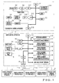
- Fig. 1 shows a color management apparatus for a printing press according to an embodiment of the present invention.
- the color management apparatus comprises a main control apparatus 1 and a colorimetry control apparatus 2 for controlling a colorimeter (to be described later) under the control of the main control apparatus 1.
- a control apparatus 5 of a color proofing apparatus, a control apparatus 6 of a printing press A, a control apparatus 7 of a printing press B, a control apparatus 8 of a printing press C, and a printing plate printing apparatus 9 are connected to the main control apparatus 1.
- the color proofing apparatus, the printing press A, the printing press B, and the printing press C are not shown in Fig. 1.
- the main control apparatus 1 comprises a CPU (Central Processing Unit) 1-1, RAM (Random Access Memory) 1-2, ROM (Read Only Memory) 1-3, input unit 1-4, display device 1-5, output unit 1-6, I/O interfaces 1-7 to 1-9, and memories 1-10 to 1-16 (to be described later).
- the CPU 1-1 obtains various input information supplied through the I/O interfaces 1-7 to 1-9 and performs various processing operations in accordance with a program stored in the ROM 1-3 while accessing the RAM 1-2 or memories 1-10 to 1-16.
- the colorimetry control apparatus 2 comprises a CPU 2-1, RAM 2-2, ROM 2-3, colorimeter 2-4, motor 2-5 for moving the colorimeter, rotary encoder 2-6, motor driver 2-7, counter 2-8, A/D converter 2-9, D/A converter 2-10, I/O interfaces 2-11 to 2-13, and colorimetry data memory 2-14.
- the CPU 2-1 obtains various input information supplied through the I/O interfaces 2-11 to 2-13 and performs various processing operations in accordance with a program stored in the ROM 2-3 while accessing the RAM 2-2 or memory 2-14.
- the rotary encoder 2-6 generates a rotary pulse every predetermined rotation count (angle) of the motor 2-5 and outputs the pulse to the counter 2-8.
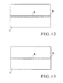
- Fig. 2 shows a printing product printed by a printing press (not shown).
- a printing product 3 a pattern is printed in a region 3a at the center, and a band-shaped color chart (color bar) 3b is printed in the margin portion except the pattern region 3a.
- the color chart 3b is formed from a number of patches having different values as the dot area percent of the respective colors, e.g., black 5%, cyan 10%, magenta 10%, and yellow 10%, or black 5%, cyan 20%, magenta 10%, and yellow 20%.
- Fig. 3 shows a color proofing print output from a color proofing apparatus (not shown).
- a color proofing print 4 a pattern is output to a region 4a at the central portion, and a band-shaped color chart (color bar) 4b is output to the margin portion except the pattern region 4a.
- the color chart 4b is formed from a number of patches having different values as the dot area percent of the respective colors, e.g., black 5%, cyan 10%, magenta 10%, and yellow 10%, or black 5%, cyan 20%, magenta 10%, and yellow 20%.
- the patch data memory 1-10 stores the positions of patches of the color chart 3b printed on the printing product 3, and the dot area percent of each ink color, which is predetermined in correspondence with each patch 3c.
- the patch data memory 1-10 stores the positions of patches 4c of the color chart 4b output to the color proofing print 4 (Fig. 3), and the dot area percent of each ink color, which is predetermined in correspondence with each patch 4c.
- Predetermined dot area percent (0% to 100%) of the respective colors e.g., the first patch 3c, 5% for black, 10% for cyan, 10% for magenta, and 10% for yellow are stored in correspondence with the first patch 3c, 5% for black, 20% for cyan, 10% for magenta, and 20% for yellow are stored in correspondence with the second patch 3c as the dot area percent of the respective colors and, 0% for black, 10% for cyan, 50% for magenta, and 20% for yellow are stored in correspondence with the third patch 3c as the dot area percent of the respective colors.
- the colorimetic value memory 1-11 stores colorimetic values obtained from the color data of each patch 3c of the color chart 3b printed on the printing product 3, which is sampled by the colorimeter 2-4.
- the colorimetic value memory 1-11 stores colorimetic values obtained from the color data of each patch 4c of the color chart 4b output to the color proofing print 4, which is sampled by the colorimeter 2-4. Color data sampling from the patches 3c and 4c using the colorimeter 2-4 will be described later.
- the colorimetic values comprise a psychometric lightness L * representing a color space and psychometric chroma coordinates a * and b * , which are defined by CIE (Commission Internationale de l'Eclairage).
- the psychometric lightness L * and psychometric chroma coordinates a * and b * are described in detail in "Specification of Colour of Materials according to the CIE 1976 (L * a * b * ) Space and the CIE 1976 (L * u * v * ) Space", JIS Z 8729, February 1980 and “Method for Specification of Colour Differences for Opaque Materials", JIS Z 8730, February 1980.
- the profile memories 1-12 to 1-14 store respective profiles (the relationships, each of which is between the dot area percent and the colorimetic values of each ink color of each printed patch) representing the respective color reproduction characteristics of the printing presses A to C.
- the profile memory 1-15 stores a profile (the relationship between the dot area percent and the colorimetic values of each ink color of each printed patch) representing the color reproduction characteristic of the color proofing apparatus. The procedure of generating the profiles to be stored in the memories 1-12 and 1-15 will be described later.
- the dot area percent memory 1-16 stores the dot area percent of each part of a printing plate for each ink color, which is used to print the printing product 3.
- Each part means a long region of the printing plate divided in the axial direction of the ink fountain roller in correspondence with a plurality of blades (to be described later). An ink amount to be supplied to a corresponding long region is adjusted by opening/closing a blade.
- the colorimeter 2-4 is attached to a ball screw (feed screw) 2-17 provided between columns 2-15 and 2-16, as shown in Fig. 4.
- the ball screw 2-17 is rotated in the forward or reverse direction by the motor 2-5.
- the colorimeter 2-4 is guided by the ball screw 2-17 and moves between the columns 2-15 and 2-16.
- a head portion 2-4a of the colorimeter 2-4 opposes a surface 2-18a of a measuring table 2-18, on which a measurement target is placed.
- the printing product 3 (Fig. 2) is printed by the printing press, and the color proofing print 4 (Fig. 3) is output from the color proofing apparatus.
- the color chart 3b formed from a number of patches 3c each having predetermined dot area percent of the respective ink colors is printed in the margin portion of the printing product 3.
- the color chart 4b is output to the margin portion of the color proofing print 4.
- the color chart 4b is formed from a number of patches 4c each having predetermined dot area percent of the respective colors.
- the operator sets the printing product 3 immediately after printing by the printing press on the measuring table 2-18 (Fig. 4) as a measurement target.
- the color chart 3b printed on the printing product 3 opposes the lower surface of the head portion 2-4a of the colorimeter 2-4.
- the operator inputs, from the input unit 1-4, the position of each patch 3c of the color chart 3b and the dot area percent of each ink color of each patch 3c (step S501).
- the input dot area percent of each ink color of each patch 3c has not a measurement value from a printing plate on which each patch 3c is printed, or the actually printed printing product 3 but a value predetermined for each ink color of each patch 3c. More specifically, a value actually input to the printing plate printing apparatus in correspondence with each patch 3c in generating a printing plate for each ink color of the printing product 3 is used as a set value, and this set value is input in step S501 as the dot area percent of each ink color of each patch 3c.
- the CPU 1-1 stores, in the patch data memory 1-10, the input position of each patch 3c of the input color chart 3b, and the dot area percent of each ink color of each patch 3c.
- the position (measurement position) of each patch 3c to be measured by the colorimeter 2-4 is calculated (step S502) and the calculated measurement position is transferred to the colorimetry control apparatus 2 (step S503).
- the transferred measurement position of each patch 3c is stored in the RAM 2-2.
- the operator turns on the start switch (not shown) of the input unit 1-4 of the printing press A.
- the start switch is turned on (YES in step S504)
- the CPU 1-1 of the main control apparatus 1 sends a measurement start command to the CPU 2-1 of the colorimetry control apparatus 2.
- the CPU 2-1 of the colorimetry control apparatus 2 rotates the motor 2-5 in the forward direction (step S505).
- the CPU 2-1 monitors the momentary moving position of the colorimeter 2-4 through the rotary encoder 2-6 (step S506).
- the colorimeter 2-4 reaches the first measurement position stored in the RAM 2-2, the color data of the patch 3c corresponding to the measurement position is sampled by the colorimeter 2-4 (step S507).
- the CPU 2-1 stores the color data (colorimetry data) from the colorimeter 2-4 in the colorimetry data memory 2-14 (step S508).
- the CPU 2-1 samples color data of the patch 3c located at the measurement position by the colorimeter 2-4 and stores the sampled color data in the colorimetry data memory 2-14. That is, the CPU 2-1 controls automatic scanning of the colorimeter 2-4, thereby sequentially sampling the color data of the patches 3c of the color chart 3b printed on the printing product 3.
- the CPU 2-1 determines whether color data sampling for all patches 3c of the color chart 3b is ended (step S509). When sampling is ended, the forward rotation of the motor 2-5 is stopped (step S510). Next, the CPU 2-1 rotates the motor 2-5 in the reverse direction (step S511) to return the colorimeter 2-4 to the home position and then stops reverse rotation of the motor 2-5 (steps S512 and S513).
- the CPU 2-1 transfers the colorimetry data of each patch 3c, which is stored in the memory 2-14, to the main control apparatus 1 (step S514).
- the transferred colorimetry data of each patch 3c is stored in the RAM 1-2.
- the CPU 1-1 of the main control apparatus 1 calculates colorimetic values from the colorimetry data of each patch 3c from the colorimetry control apparatus 2 and stores them in the colorimetic value memory 1-11 (step S515).
- the CPU 1-1 makes the colorimetic values of each patch in the colorimetic value memory 1-11 correspond to the dot area percent of each ink color of each patch 3c, which is stored in the patch data memory 1-10, in the order of data, and stores these relationships in the profile memory 1-12 as the profile of the printing press A (step S516).
- the operator sets the color proofing print 4 immediately after output from the color proofing apparatus on the measuring table 2-18 (Fig. 4) as a measurement target.
- the color chart 4b output to the color proofing print 4 opposes the lower surface of the head portion 2-4a of the colorimeter 2-4.
- a dot area percent predetermined in correspondence with each ink color of each patch 4c is input to the color proofing apparatus.
- the input dot area percent of each ink color of each patch 4c has the same value as that actually input to the printing plate printing apparatus in correspondence with each patch 3c in generating the printing plate for each ink color of the printing product 3.
- the operator inputs, from the input unit 1-4, the position of each patch 4c of the color chart 4b and the dot area percent of each ink color of each patch 4c (step S601).
- the input dot area percent of each ink color of each patch 4c has not a measurement value from the color proofing print 4 but a value predetermined for each patch 4c. More specifically, a value actually input to the color proofing apparatus in correspondence with each patch 4c in outputting the color proofing print 4 is used as a set value, and this set value is input in step S601 as the dot area percent of each ink color of each patch 4c.
- the input set value of the dot area percent of each ink color of each patch 4c is the same as the value input to the printing plate printing apparatus in correspondence with each patch 3c in generating the printing plate for each ink color of the printing product 3.
- the CPU 1-1 stores, in the patch data memory 1-10, the input position of each patch 4c of the input color chart 4b, and the dot area percent of each ink color of each patch 4c.
- the CPU 1-1 calculates the position (measurement position) of each patch 4c to be measured by the colorimeter 2-4 (step S602), and transfers the calculated measurement position of each patch 4c to the colorimetry control apparatus 2 (step S603).
- the transferred measurement position of each patch 4c is stored in the RAM 2-2.
- step S604 the operator turns on the start switch (not shown) of the input unit 1-4.
- the CPU 1-1 of the main control apparatus 1 sends a measurement start command to the CPU 2-1 of the colorimetry control apparatus 2.
- the CPU 2-1 of the colorimetry control apparatus 2 rotates the motor 2-5 in the forward direction (step S605).
- the CPU 2-1 monitors the momentary moving position of the colorimeter 2-4 through the rotary encoder 2-6 (step S606).
- the CPU 2-1 samples the color data of the patch 4c located at the measurement position by the colorimeter 2-4 (step S607).
- the CPU 2-1 stores the color data (colorimetry data) output from the colorimeter 2-4 in the colorimetry data memory 2-14 (step S608).
- the CPU 2-1 samples the color data of the patch 4c located at the measurement position by the colorimeter 2-4 and stores the sampled color data in the colorimetry data memory 2-14. That is, the CPU 2-1 controls automatic scanning of the colorimeter 2-4, thereby sequentially sampling the color data of the patches 4c of the color chart 4b output to the color proofing print 4.
- the CPU 2-1 determines whether color data sampling for all patches 4c of the color chart 4b is ended (step S609). When sampling is ended, the forward rotation of the motor 2-5 is stopped (step S610). Next, the CPU 2-1 rotates the motor 2-5 in the reverse direction (step S611) to return the colorimeter 2-4 to the home position and then stops reverse rotation of the motor 2-5 (steps S612 and S613).
- the CPU 2-1 transfers the colorimetry data of each patch 4c, which is stored in the memory 2-14, to the main control apparatus 1 (step S614).
- the transferred colorimetry data of each patch 4c is stored in the RAM 1-2.
- the CPU 1-1 of the main control apparatus 1 calculates colorimetic values (L * a * b * ) from the colorimetry data of each patch 4c from the colorimetry control apparatus 2 and stores them in the colorimetic value memory 1-11 (step S615).
- the CPU 1-1 makes the colorimetic values in the colorimetic value memory 1-11 correspond with the colorimetic values with the dot area percent of each color of each patch 4c, which is stored in the patch data memory 1-10, in the order of data, and stores these relationships in the profile memory 1-15 as the profile of the color proofing apparatus (step S616).
- the operator inputs, from the input unit 1-4, the dot area percent of each part of a printing plate for each ink color, which is used to generate the printing plate and print the printing product by the printing press A (step S701).
- the input dot area percent of each part of the printing plate for each ink color has not a measurement value from the printing plate but a value predetermined for the part of the printing plate. More specifically, the value actually input to the printing plate printing apparatus in generating the printing plate for each ink color is used as a set value, and this set value is input in step S701 as the dot area percent of each part for each ink color. This dot area percent is the same as that input to the color proofing apparatus to generate the color proofing print.
- the CPU 1-1 obtains colorimetic values (three values) corresponding to a dot area percent equal or closest to the dot area percent of each part for generating the printing plate for each ink color from the profile of the printing press in A the profile memory 1-12 (step S702). Next, the CPU 1-1 obtains the dot area percent of each ink color having colorimetic values equal or closest to the colorimetic values (three values) obtained in step S702 from the profile of the color proofing apparatus in the profile memory 1-15 (step S703). The CPU 1-1 inputs the obtained data of dot area percent of each ink color to the color proofing apparatus (step S704).
- the color proofing apparatus outputs a color proofing print on the basis of the dot area percent of each ink color supplied from the main control apparatus 1 (step S705). This enables the printing products printed by the printing press A and the color proofing print output from the color proofing apparatus to have the same tint.
- an alternative printing press B is used for printing. In this case, color matching is performed between the printing press A and printing press B.
- a printing product 10 shown in Fig. 8 is printed by the printing press B.
- a color chart 10b is printed in the margin portion of the printing product 10.
- the color chart 10b is formed from a number of patches 10c each having predetermined dot area percent of the respective ink colors. The operator sets the printing product 10 immediately after printing by the printing press B on the measuring table 2-18 (Fig. 4) as a measurement target.
- the operator inputs the position of each patch 10c of the color chart 10b and the dot area percent of each ink color of each patch 10c to the input unit 1-4 (step S901).
- the input dot area percent of each ink color of each patch 10c has not a measurement value from a printing plate on which each patch 10c is printed, or the actually printed printing product 10 but a value predetermined for each ink color of each patch 10c.
- a value actually input to the printing plate printing apparatus 9 in correspondence with each patch 10c in generating a printing plate for each ink color is used as a set value, and this set value is input in step S901 as the dot area percent of each ink color of each patch 10c.
- the CPU 1-1 stores, in the patch data memory 1-10, the input position of each patch 10c of the input color chart 10b, and the dot area percent of each ink color of each patch 10c.
- the position (measurement position) of each patch 10c to be measured by the colorimeter 2-4 is calculated (step S902) and the calculated measurement position of each patch 10c is transferred to the colorimetry control apparatus 2 (step S903).
- the transferred measurement position of each patch 10c is stored in the RAM 2-2.
- step S904 the operator turns on the start switch (not shown) of the printing press B in the input unit 1-4.
- the start switch is turned on (step S904)
- the CPU 1-1 of the main control apparatus 1 sends a measurement start command to the CPU 2-1 of the colorimetry control apparatus 2.
- the CPU 2-1 of the colorimetry control apparatus 2 rotates the motor 2-5 in the forward direction (step S905).
- the CPU 2-1 transfers the colorimetry data of each patch 10c to the main control apparatus 1 (step S914).
- the transferred colorimetry data of each patch 10c is stored in the RAM 1-2.
- the CPU 1-1 of the main control apparatus 1 calculates colorimetic values from the colorimetry data of each patch 10c from the colorimetry control apparatus 2 and stores them in the colorimetic value memory 1-11 (step S915).
- the CPU 1-1 makes the colorimetic values of each patch in the colorimetic value memory 1-11 correspond to the dot area percent of each ink color of each patch 10c, which is stored in the patch data memory 1-10, in the order of data, and stores these relationships in the profile memory 1-13 as the profile of the printing press B (step S916).
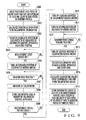
- the operator inputs the dot area percent of each part of a printing plate, for each ink color, of a printing product to be printed by the printing press A to the input unit 1-4 (step S101).
- the input dot area percent of each part of the printing plate for each ink color has not a measurement value from the printing plate but a value predetermined for the part of the printing plate. More specifically, the value actually input to the printing plate printing apparatus 9 in generating the printing plate for each ink color is used as a set value, and this set value is input in step S101 as the dot area percent of each part for each ink color.
- the CPU 1-1 obtains colorimetic values corresponding to a dot area percent equal or closest to the dot area percent of each part for generating the printing plate, for each ink color, of a printing product to be printed from the profile of the printing press A in the profile memory 1-12 (step S102). Next, the CPU 1-1 obtains the dot area percent of each ink color having colorimetic values equal or closest to the colorimetic values obtained in step S102 from the profile of the printing press B stored in the profile memory 1-13 (step S103).
- the CPU 1-1 supplies the obtained data of dot area percent of each part for each ink color to the printing plate printing apparatus 9 (step S104).
- the printing plate printing apparatus 9 generates a printing plate for each ink color used for the printing press B (step S105).
- the printing plate for each ink color is generated by plate making on the machine. That is, a plate making unit added to the printing unit of each ink color is operated to print an image on a raw plate attached to the plate cylinder for that ink color.
- the CPU 1-1 sends the obtained dot area percent of each ink color of each part to the control apparatus 7 of the printing press B.
- Fig. 11 shows the control apparatus 7 of the printing press B.
- the control apparatus 7 is constructed by a CPU 7-1, RAM 7-2, ROM 7-3, input/output interfaces (I/O) 7-4 and 7-51 to 7-5n, memories 7-6 to 7-9, and blade drive units D1 to Dn.
- the blade drive units D1 to Dn are provided in correspondence with n blades (ink fountain keys) juxtaposed in the axial direction of an ink fountain roller (not shown).
- the memory 7-6 stores the dot area percent of each ink color of each part to generate a printing plate for each ink color to be used for printing.
- the memory 7-7 stores the dot area percent of each ink color in a region corresponding to each blade of the printing press B.
- the memory 7-8 stores a table of ink color dot area percent and blade opening ratio for the printing press B.
- the memory 7-9 stores the opening ratio of each blade for each printing unit of the printing press B.
- the CPU 7-1 obtains the dot area percent of a region corresponding to each blade for each ink color in the printing press B from the dot area percent of each part for each ink color, which is supplied from the main control apparatus 1 (step S106).
- the dot area percent of each part for each ink color, which is supplied for the main control apparatus 1 is stored in the memory 7-6, and the obtained dot area percent of a region corresponding to each blade of the printing press B for each ink color is stored in the memory 7-7.
- the CPU 7-1 obtains the opening ratio of each blade for each ink color from the obtained dot area percent of a region corresponding to each blade of the printing press B for each ink color using the table of ink color dot area percent and blade opening ratio stored in the memory 7-8 (step S107).
- the obtained opening ratio of each blade for each ink color is stored in the memory 7-9.
- the CPU 7-1 drives the blade drive units D1 to Dn, thereby setting the opening ratio of each blade of the printing press B for each ink color to the obtained opening ratio of each blade for each ink color.
- the CPU 7-1 performs printing by the printing press B using the printing plate for the printing press B, which is generated by plate making on the machine (step S108).
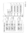
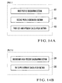
- Figs. 14A and 14B show the functional blocks of the CPU 1-1 in the main control apparatus 1 and the CPU 7-1 in the control apparatus 7 (Fig. 11) of the printing press B.
- the CPU 1-1 has a first profile generation section 101 and second profile generation section 102.
- the first profile generation section 101 generates the first profile representing the color reproduction characteristics of the printing press A using the color data of a number of patches printed by the printing press A and the dot area percent of each ink color defined for each patch.
- the first profile generation section 101 executes steps S515 and S516 in Fig. 5.
- the second profile generation section 102 generates the second profile representing the color reproduction characteristics of the printing press B using the color data of a number of patches printed by the printing press B and the dot area percent of each ink color defined for each patch.
- the second profile generation section 102 executes steps S915 and S916 in Fig. 9.
- a first dot area percent calculation section 103 obtains the dot area percent of each ink color to be used to print a printing product by the printing press B on the basis of the first and second profiles generated by the first and second profile generation sections 101 and 102.
- the first dot area percent calculation section 103 executes steps S102 and S103 in Fig. 10.
- the CPU 7-1 has a second dot area percent calculation section 201 and ink supply amount calculation section 202.
- the second dot area percent calculation section 201 obtains the dot area percent of a region corresponding to each ink fountain key of the printing press B for each ink color from the dot area percent of each ink color, which is obtained by the first dot area percent calculation section 103.
- the second dot area percent calculation section 201 executes step S106 in Fig. 10.
- the ink supply amount calculation section 202 obtains the ink supply amount to be used to print a printing product by the printing press B on the basis of the dot area percent corresponding to each ink fountain key, which is obtained by the second dot area percent calculation section 201.
- the ink supply amount calculation section 202 executes step S107 in Fig. 10.
- the first and second profile generation sections 101 and 102 may be formed from a single printing profile generation section.
- the second dot area percent calculation section 201 and ink supply amount calculation section 202 may be provided not in the control section 7 of the printing press B but in the main control apparatus 1.
- the tint of a printing product to be printed by the printing press A can be made to match that of a printing product printed by the printing press B.
- the operator need not adjust the ink supply amount referring to the color proofing print during printing.
- the color matching time can be shortened, and the printing materials are not wasted.
- the color chart 3b is printed on the margin portion except the pattern region 3a of the printing product 3, and the color chart 4b is output to the margin portion except the pattern region 4a of the color proofing print 4.
- the printing portion 3 and color proofing print 4 may not have any patterns and may have only the color chart 3b printed thereon and the color proofing print 4 output thereto, respectively.
- a case wherein a printing press A to be used for printing becomes unavailable, and an alternative printing press B is used.
- the present invention may be applied to a case wherein a printing press other than the printing press A is used for printing.
- colorimetic values most approximate to the set dot area percent of each ink color are selected.
- the colorimetic values may be corrected in accordance with the degree of approximation, and the color proofing profile or the profile of the printing press B may be referred to.
- the dot area percent of each ink color may be corrected and output for proofing in accordance with the degree of approximation.
- the dot area percent of each ink color in printing a printing product by the second printing press is obtained on the basis of the first profile representing the color reproduction characteristic of the first printing press and the second profile representing the color reproduction characteristic of the second printing press, thereby printing a printing product, by the second printing press, in the same tint as by the first printing press.
Landscapes
- Engineering & Computer Science (AREA)
- Multimedia (AREA)
- Signal Processing (AREA)
- Inking, Control Or Cleaning Of Printing Machines (AREA)
Applications Claiming Priority (2)
| Application Number | Priority Date | Filing Date | Title |
|---|---|---|---|
| JP2000145578 | 2000-05-17 | ||
| JP2000145578 | 2000-05-17 |
Publications (2)
| Publication Number | Publication Date |
|---|---|
| EP1156667A2 true EP1156667A2 (fr) | 2001-11-21 |
| EP1156667A3 EP1156667A3 (fr) | 2004-05-06 |
Family
ID=18652065
Family Applications (1)
| Application Number | Title | Priority Date | Filing Date |
|---|---|---|---|
| EP01250167A Withdrawn EP1156667A3 (fr) | 2000-05-17 | 2001-05-15 | Procédé et dispositif de gestion de couleurs dans une machine à imprimer |
Country Status (2)
| Country | Link |
|---|---|
| US (1) | US6615727B2 (fr) |
| EP (1) | EP1156667A3 (fr) |
Cited By (1)
| Publication number | Priority date | Publication date | Assignee | Title |
|---|---|---|---|---|
| JP2012186748A (ja) * | 2011-03-08 | 2012-09-27 | Seiko Epson Corp | 印刷制御装置および印刷制御方法 |
Families Citing this family (6)
| Publication number | Priority date | Publication date | Assignee | Title |
|---|---|---|---|---|
| US20040201211A1 (en) * | 2002-07-10 | 2004-10-14 | Weiss Mark A. | Proofing paper with pre-printed color bar |
| US7259888B2 (en) * | 2003-01-03 | 2007-08-21 | Eastman Kodak Company | Image file bit depth expansion and subsequent manipulation |
| US6792864B2 (en) * | 2003-01-03 | 2004-09-21 | Eastman Kodak Company | Image file data equivalence algorithms respective to output devices |
| JP4276046B2 (ja) * | 2003-10-30 | 2009-06-10 | 株式会社小森コーポレーション | 印刷機のインキ供給量調整方法および装置 |
| JP4495068B2 (ja) * | 2005-11-14 | 2010-06-30 | 三菱重工業株式会社 | 印刷管理システム及びその方法並びにプログラム |
| ES2878103T3 (es) * | 2016-08-01 | 2021-11-18 | I Mer Co Ltd | Máquina de impresión que tiene rodillo ductor, dispositivo de corrección y procedimiento de corrección de la máquina de impresión |
Citations (7)
| Publication number | Priority date | Publication date | Assignee | Title |
|---|---|---|---|---|
| US4564860A (en) * | 1983-01-31 | 1986-01-14 | Komori Printing Machinery Co., Ltd. | Method and system of measuring image area |
| US4901254A (en) * | 1986-08-05 | 1990-02-13 | Fogra Deutsche Forschungsgellschaft fur Druckund | Method and apparatus for influencing the colour appearance of a colored area in a printing process |
| EP0394681A2 (fr) * | 1989-04-24 | 1990-10-31 | Heidelberger Druckmaschinen Aktiengesellschaft | Procédé pour contrôler l'encrage dans une machine d'impression avec limitation de l'épaisseur de la couche d'encre et de l'augmentation de la valeur tonale |
| EP0475554A2 (fr) * | 1990-02-05 | 1992-03-18 | Scitex Corporation Ltd. | Appareil et procédé de calibrage de couleurs |
| US5579031A (en) * | 1992-12-15 | 1996-11-26 | E. I. Du Pont De Nemours And Company | Color matching method and apparatus |
| EP1071275A1 (fr) * | 1999-01-18 | 2001-01-24 | Fuji Photo Film Co., Ltd. | Procede de correction de couleur |
| EP1080892A2 (fr) * | 1999-09-06 | 2001-03-07 | Komori Corporation | Procédé et dispositif de gestion de couleurs dans une machine à imprimer |
Family Cites Families (2)
| Publication number | Priority date | Publication date | Assignee | Title |
|---|---|---|---|---|
| US5687300A (en) * | 1995-03-27 | 1997-11-11 | Linotype-Hell Ag | Process for creating five to seven color separations used on a multicolor press |
| US6137594A (en) * | 1997-03-25 | 2000-10-24 | International Business Machines Corporation | System, method and program for converting an externally defined colorant CMYK into an equivalent colorant (C'M'Y'K') associated with a given printer |
-
2001
- 2001-05-15 EP EP01250167A patent/EP1156667A3/fr not_active Withdrawn
- 2001-05-16 US US09/859,757 patent/US6615727B2/en not_active Expired - Fee Related
Patent Citations (7)
| Publication number | Priority date | Publication date | Assignee | Title |
|---|---|---|---|---|
| US4564860A (en) * | 1983-01-31 | 1986-01-14 | Komori Printing Machinery Co., Ltd. | Method and system of measuring image area |
| US4901254A (en) * | 1986-08-05 | 1990-02-13 | Fogra Deutsche Forschungsgellschaft fur Druckund | Method and apparatus for influencing the colour appearance of a colored area in a printing process |
| EP0394681A2 (fr) * | 1989-04-24 | 1990-10-31 | Heidelberger Druckmaschinen Aktiengesellschaft | Procédé pour contrôler l'encrage dans une machine d'impression avec limitation de l'épaisseur de la couche d'encre et de l'augmentation de la valeur tonale |
| EP0475554A2 (fr) * | 1990-02-05 | 1992-03-18 | Scitex Corporation Ltd. | Appareil et procédé de calibrage de couleurs |
| US5579031A (en) * | 1992-12-15 | 1996-11-26 | E. I. Du Pont De Nemours And Company | Color matching method and apparatus |
| EP1071275A1 (fr) * | 1999-01-18 | 2001-01-24 | Fuji Photo Film Co., Ltd. | Procede de correction de couleur |
| EP1080892A2 (fr) * | 1999-09-06 | 2001-03-07 | Komori Corporation | Procédé et dispositif de gestion de couleurs dans une machine à imprimer |
Cited By (1)
| Publication number | Priority date | Publication date | Assignee | Title |
|---|---|---|---|---|
| JP2012186748A (ja) * | 2011-03-08 | 2012-09-27 | Seiko Epson Corp | 印刷制御装置および印刷制御方法 |
Also Published As
| Publication number | Publication date |
|---|---|
| US20010042483A1 (en) | 2001-11-22 |
| US6615727B2 (en) | 2003-09-09 |
| EP1156667A3 (fr) | 2004-05-06 |
Similar Documents
| Publication | Publication Date | Title |
|---|---|---|
| EP1080892B2 (fr) | Procédé et dispositif de gestion de couleurs dans une machine à imprimer | |
| CA2284305C (fr) | Methode d'etablissement de profil et d'etalonnage d'une machine a imprimer a commande numerique et ayant un cliche permanent | |
| JP5022682B2 (ja) | カラー印刷機の印刷画像品質管理方法及び印刷画像品質管理装置 | |
| EP1188561A2 (fr) | Procédé et dispositif de gestion de couleurs dans une machine à imprimer | |
| EP0983852B1 (fr) | Méthode et dispositif de contrôle de l'épaisseur d'un film d'encre pour une presse d'impression à plusieurs couleurs | |
| EP1156667A2 (fr) | Procédé et dispositif de gestion de couleurs dans une machine à imprimer | |
| JP2007030348A (ja) | 印刷機のインキ供給量調整方法および装置 | |
| JP2003154629A (ja) | 両面印刷機の印刷濃度管理装置 | |
| CN101497259B (zh) | 彩色印刷机的印刷图像品质管理方法及装置 | |
| EP1839863A2 (fr) | Dispositif de réglage de l'encre, imprimante et procédé d'impression | |
| EP1839864A2 (fr) | Dispositif de commande de l'encre, imprimante et méthode d'impression | |
| JP2008105423A (ja) | アニロックス印刷機のための製版 | |
| JP4958598B2 (ja) | 印刷機の色合わせ方法及び色合わせ装置 | |
| US20010003955A1 (en) | Method of presetting printing machines | |
| JP4515610B2 (ja) | 印刷機の色管理方法および装置 | |
| JP3664959B2 (ja) | 印刷機における色調制御方法及び装置 | |
| JP4373641B2 (ja) | 色管理装置 | |
| JP4227492B2 (ja) | 印刷物の品質管理方法および装置 | |
| JP2008114466A (ja) | 色調管理システム並びに印刷機及び印刷方法 | |
| JP4139100B2 (ja) | 印刷作業指示システム | |
| JP2006103050A (ja) | 印刷機のインキ供給量調整方法および装置 | |
| JP2002086688A (ja) | 印刷機の色管理方法および装置 | |
| JP4206684B2 (ja) | 印刷方法及び印刷色制御装置 | |
| JP7368644B2 (ja) | 多色の印刷製品のLab目標色値を適合させるための方法 | |
| JP2005231256A (ja) | カラー印刷機の印刷画像品質管理方法及び印刷画像品質管理装置 |
Legal Events
| Date | Code | Title | Description |
|---|---|---|---|
| PUAI | Public reference made under article 153(3) epc to a published international application that has entered the european phase |
Free format text: ORIGINAL CODE: 0009012 |
|
| 17P | Request for examination filed |
Effective date: 20010613 |
|
| AK | Designated contracting states |
Kind code of ref document: A2 Designated state(s): AT BE CH CY DE DK ES FI FR GB GR IE IT LI LU MC NL PT SE TR |
|
| AX | Request for extension of the european patent |
Free format text: AL;LT;LV;MK;RO;SI |
|
| PUAL | Search report despatched |
Free format text: ORIGINAL CODE: 0009013 |
|
| AK | Designated contracting states |
Kind code of ref document: A3 Designated state(s): AT BE CH CY DE DK ES FI FR GB GR IE IT LI LU MC NL PT SE TR |
|
| AX | Request for extension of the european patent |
Extension state: AL LT LV MK RO SI |
|
| AKX | Designation fees paid |
Designated state(s): AT BE CH CY DE DK ES FI FR GB GR IE IT LI LU MC NL PT SE TR |
|
| 17Q | First examination report despatched |
Effective date: 20050317 |
|
| STAA | Information on the status of an ep patent application or granted ep patent |
Free format text: STATUS: THE APPLICATION IS DEEMED TO BE WITHDRAWN |
|
| 18D | Application deemed to be withdrawn |
Effective date: 20080820 |