EP1156182B1 - Venetian blind with variable tilting - Google Patents
Venetian blind with variable tilting Download PDFInfo
- Publication number
- EP1156182B1 EP1156182B1 EP01304392A EP01304392A EP1156182B1 EP 1156182 B1 EP1156182 B1 EP 1156182B1 EP 01304392 A EP01304392 A EP 01304392A EP 01304392 A EP01304392 A EP 01304392A EP 1156182 B1 EP1156182 B1 EP 1156182B1
- Authority
- EP
- European Patent Office
- Prior art keywords
- auxiliary tilt
- cross
- rungs
- tilt cord
- adjacent
- Prior art date
- Legal status (The legal status is an assumption and is not a legal conclusion. Google has not performed a legal analysis and makes no representation as to the accuracy of the status listed.)
- Expired - Lifetime
Links
Images


Classifications
-
- E—FIXED CONSTRUCTIONS
- E06—DOORS, WINDOWS, SHUTTERS, OR ROLLER BLINDS IN GENERAL; LADDERS
- E06B—FIXED OR MOVABLE CLOSURES FOR OPENINGS IN BUILDINGS, VEHICLES, FENCES OR LIKE ENCLOSURES IN GENERAL, e.g. DOORS, WINDOWS, BLINDS, GATES
- E06B9/00—Screening or protective devices for wall or similar openings, with or without operating or securing mechanisms; Closures of similar construction
- E06B9/24—Screens or other constructions affording protection against light, especially against sunshine; Similar screens for privacy or appearance; Slat blinds
- E06B9/26—Lamellar or like blinds, e.g. venetian blinds
- E06B9/28—Lamellar or like blinds, e.g. venetian blinds with horizontal lamellae, e.g. non-liftable
- E06B9/30—Lamellar or like blinds, e.g. venetian blinds with horizontal lamellae, e.g. non-liftable liftable
- E06B9/303—Lamellar or like blinds, e.g. venetian blinds with horizontal lamellae, e.g. non-liftable liftable with ladder-tape
- E06B9/307—Details of tilting bars and their operation
-
- E—FIXED CONSTRUCTIONS
- E06—DOORS, WINDOWS, SHUTTERS, OR ROLLER BLINDS IN GENERAL; LADDERS
- E06B—FIXED OR MOVABLE CLOSURES FOR OPENINGS IN BUILDINGS, VEHICLES, FENCES OR LIKE ENCLOSURES IN GENERAL, e.g. DOORS, WINDOWS, BLINDS, GATES
- E06B9/00—Screening or protective devices for wall or similar openings, with or without operating or securing mechanisms; Closures of similar construction
- E06B9/24—Screens or other constructions affording protection against light, especially against sunshine; Similar screens for privacy or appearance; Slat blinds
- E06B9/26—Lamellar or like blinds, e.g. venetian blinds
- E06B9/28—Lamellar or like blinds, e.g. venetian blinds with horizontal lamellae, e.g. non-liftable
- E06B2009/285—Means for actuating a rod (being tilt rod or lift rod)
Definitions
- This invention relates to a venetian blind, the slats of which can be tilted to different angles relative to one another (i.e., variably tilted).
- the slats of such a blind have been tilted, so that they are closed in a normal fashion, the slats of a lower portion of the blind, in front of a room window, can be tilted to an open position to provide a view of the outside, while at the same time, the slats of the blind's upper portion can be left tilted in a closed position to reduce the amount of sunlight coming into the room.
- an upper portion of the blind can be tilted to an open position to admit some sunlight into the room, while at the same time, the slats of the blind's lower portion can be left tilted in a closed position to provide privacy in the room and/or reduce the amount of sunlight in the room, for example to prevent glare from interfering with the use of computer or television screens in the room.
- Venetian blinds have generally included: a horizontally-elongated head rail; a plurality of horizontally-elongated slats beneath the head rail and parallel to it; and at least two slat-supporting ladders movably suspended from the head rail and supporting the slats in vertically spaced apart relationship.
- each ladder generally has had front and rear, vertically-extending members that have been connected to each other by a plurality of vertically-spaced cross-rungs. Supported on each cross-rung, between the vertically-extending members of its ladder, has been one length-wise side of a slat.
- the head rail generally has had an adjusting mechanism for moving the ladders, so that the vertically-extending members of each ladder move in opposite vertical directions relative to one another, to pivot each slat about its length-wise axis.
- auxiliary tilt cord has been adapted to engage at least one of the vertically-extending members of the blind's ladders, at an intermediate location along its height, and when manipulated, to adjust the angle of pivot of the slats below the intermediate location. See US 2 427 266, US 2 719 586, US 2 751 000, US 4 940 070,
- a venetian blind including:
- the venetian blind is characterized in that:
- Figures 1-5 show a first embodiment of a venetian blind 1 of this invention.
- the blind 1 has a generally conventional, horizontally-extending head rail 3, horizontally-extending bottom rail (not shown) and pair of vertically-extending slat-supporting ladders 5 and 7.
- the ladders 5,7 are suspended from the head rail 3 in a conventional manner so as to be movable by a pair of tilt pivot swivels 9 and 11, respectively, in the head rail.
- the ladders 5,7 hold a plurality of conventional horizontally-elongated slats 13, so that they are suspended horizontally from the head rail 3.
- a conventional, manually operable, cord loop 8 is suspended from the front of the head rail 3.
- the cord loop 8 is connected to the tilt swivels 9, 11 in the head rail 3.
- the tilt swivels 9,11 can move the front and rear of the ladders 5,7, relative to each other, to adjust the angular position or tilt of all the slats 13 (i.e., pivot the slats about their longitudinal axes) in response to movement of the cord loop 8.
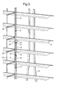
- Figures 2 and 3 show best a pair of vertically-extending auxiliary tilt cords 14, 15 at the rear of the blind 1 and a first or rear, vertical member 17,19 and a second or front, vertical member 18, 20 of each ladder 5,7 of the blind.
- the rear and front vertical members 17-20 extend parallel to each other and are interconnected by a plurality of laterally-extending cross-rungs 29 (see Figure 3).
- the cross-rungs 29 are spaced vertically apart along the height of the vertical members 17-20 of the ladders 5, 7 at a regular pitch (which is the distance between two vertically adjacent slat supporting rungs 29).
- Each vertically-extending auxiliary tilt cord 14, 15 is located adjacent the rear vertical member 17, 19 of one of the ladders 5, 7, respectively.
- Each tilt cord 14, 15 is connected to, and engages, its adjacent rear vertical member 17, 19 at a plurality of predetermined intermediate locations along the height of the tit cord and its adjacent rear vertical member.
- the plurality of guiding loops 21 are preferably regularly spaced along the height of each rear vertical member 17,19, and the plurality of beads 23 are preferably regularly spaced along the height of each auxiliary tilt cord 14,15.
- the locations of the cross-rungs 29 and the locations of intermediate guiding loops 21, between the top and bottom of the rear vertical members 17,19, preferably do not coincide horizontally, and preferably, the integral values of X 1 and X 2 are identical.
- the number of guiding loops 21 on each of the rear vertical members 17,19 is preferably the same, and each guiding loop on each of the rear vertical members 17,19 is preferably aligned horizontally with a guiding loop on the other rear vertical member(s).
- the number of beads 23 on each of the auxiliary tilt cords 14,15 is preferably the same, and each bead on each of the auxiliary tilt cords is preferably aligned horizontally with a bead on the other auxiliary tilt cord(s).
- the number of engaging collars 25 on each of the auxiliary tilt cords 14,15 is also preferably the same, and each collar 25 on each of the auxiliary tilt cords 14,15 is preferably aligned horizontally with a collar on the other auxiliary tilt cord(s).
- the number of beads 23 spaced along each of the auxiliary tilt cords 14,15 is equal to, or greater than, preferably equal to, the number of engaging collars 25 spaced along the auxiliary tilt cord.
- the rearwardly-extending guiding loops 21 on the rear vertical members 17,19 of the ladders 5, 7 keep the auxiliary tilt cords 14,15 and the rear vertical members in close proximity to each other.
- the guiding loops 21 of each rear vertical member 17,19 prevent the adjacent auxiliary tilt cord 14,15, respectively, around which the guiding loops extend, from forming unsightly loops when the blind 1 is raised or from becoming entangled during use of the blind.
- P (loops) equals P (rungs)
- the number of loops 21 equals the number of cross-rungs 29. This is illustrated in Figures 2, 3 where, between each adjacent pair of cross-rungs 29 of each ladder 5, 7, one guiding loop 21 is provided.
- the greater the number of loops 21, the better the auxiliary tilt cords 14,15 are held to the rear vertical members 17,19 during operation of the blind 1.
- each engaging collar 25, slidably located on an auxiliary tilt cord 14,15 has a generally circular horizontal cross-section.
- Each collar also has a central vertically-extending passage 27, through which its auxiliary tilt cord can pass vertically but not the beads 23 on its auxiliary tilt cord.
- Each collar 25 further has a radially inwardly-extending vertical slit 28 which opens into its central passage 27.
- one of the auxiliary tilt cords 14,15 can be pushed through the slit 28 of each collar into its central passage 27.
- Each collar 25 also has a horizontal circumference greater than each guiding loop 21, so that the exterior size of the collar 25 is too large for the guiding loops 21 to pass vertically over the collar.
- the guiding loops 21 each have a diameter greater than the horizontal circumference of each bead 23, so that the beads can pass vertically through the guiding loops.
- the blind 1 had only a single engaging collar 25 on each auxiliary tilt cord 14, 15, the blind would have two sections of slats 13, the lower one of which would be operated by the auxiliary tilt cords 14, 15.
- the auxiliary tilt cords 14,15 are raised (e.g., by pulling on the rear of the cord loop 8)
- their beads 23 beneath their engaging collars 25 would be moved upwardly until they engage and lift their collars 25, which would then slide upwardly along the tilt cords until they engage the adjacent next higher loops 21 on the adjacent rear vertical members 17,19 of the ladders 5, 7.
- the collars would then move upwardly, thereby lifting the next higher loops 21 and the portions of the rear vertical members 17,19 below the next higher loops 21.
- the slats of the lower section 13A of the blind 1 of Figures 1-5 can be tilted relative to the slats of the middle and upper sections 13B,13C by moving the auxiliary tilt cords 14,15 upwardly together (e.g., by pulling on the rear of the cord loop 8), so that the lower bead 23A of each tilt cord moves upwardly and engages the tilt cord's lower engaging collar 25A (above the lower bead 23A), which then slides upwardly along the tilt cord until it engages the tilt cord's first adjacent, next higher loop 21A of its adjacent rear vertical member 17,19 of the ladders 5,7 and then lifts the rear of all the slats 13 of the lower section 13A below this first next higher loop 21A .
- an upper bead 23B of each tilt cord moves further upwardly and engages the tilt cord's upper engaging collar 25B (above the upper bead 23B), which then slides upwardly along the tilt cord until it engages the tilt cord's second adjacent, next higher loop 21B of its adjacent rear vertical member 17,19 of the ladders 5,7 and then lifts the rear of all the slats 13 of the middle section 13B below the second next higher loop 21B.
- auxiliary tilt cords 14,15 of the blind 1are then moved still further upwardly all the slats 13 of the lower and middle sections 13A,13B, below the second next higher loops 21B, would continue to be so-tilted until they would be completely open. However, the slats of the upper section 13C would remain in a normal closed position. If the auxiliary tilt cords 14,15 are thereafter moved yet further upwardly, all the slats of the lower and middle sections 13A,13B, below the second next higher loops 21B, would continue to be so-tilted until they would be in an abnormal closed position (i.e., downwardly-inclined from rear to front). Although the slats of the upper section 13C would still remain in a normal closed position, they could be opened simply by then moving the rear vertical members 17,19 of the ladders 5,7 downwardly together (e.g., by pulling on the front of the cord loop 8).
- the blind 1 would have more than three sections of slats 13 (between engaging collars 25) which could be progressively tilted to greater angles of openness, relative to one another, so as to provide a more gradual change in the tilting of the slats over the height of the blind.
- the blind 1 has a first or left (as viewed in Figure 1), tilt swivel 9 and a second or right (as viewed in Figure 1), tilt swivel 11 in the head rail 3 for moving its left and right ladders 5, 7 to tilt its horizontal slats 13.
- the slats can be tilted by moving the interconnected, rear and front, vertical members 17, 18 and 19,20 of the ladders 5, 7 in a conventional manner in opposite vertical directions, to alter the angular orientation of the ladders' crossrungs 29.
- Each of the slats 13 is supported on a confronting one of the crossrungs 29, between the rear and front, vertical members of each ladder, and thereby is pivoted by each tilt swivel 9,11 to the same angular position as the pair of crossrungs 29 which support it.
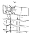
- Figure 4 shows the left tilt swivel 9 which, in accordance with this invention, can both: i) move the rear and front, vertical members 17, 18 of the left ladder 5 in opposite vertical directions to pivot fully its cross-rungs 29 and the left side of the slats 13 thereon between the front and the rear of the blind 1; and ii) move vertically the left auxiliary tilting cords 14.
- the left tilt swivel 9 has a conventional adjusting pulley 31 which rotates about the longitudinal axis of the head rail 3 in response to vertical movement of the cord loop 8.
- About the axis of rotation of the adjusting pulley 31 is a V-shaped annular groove 32 which, as shown, converges from the perimeter of the pulley towards it axis.
- the rear and front, vertical members 17, 18 of the left ladder 5 are connected by a conventional loop 33 of the material of the rear and front, vertical members which passes closely around the adjusting pulley 31 within its V-shaped annular groove 32.
- the annular groove 32 frictionally engages the loop 33, so that the rear and front, vertical members 17, 18 move vertically in opposite directions, with rotation of the adjusting pulley 31, between the normal closed and abnormal closed positions of the slats 13.
- Figure 4 also shows that the left tilt swivel 9 has a conventional winding drum 34 that is connected to, and coaxial with, the adjusting pulley 31.
- the winding drum 34 rotates about the longitudinal axis of the head rail 3 with rotation of the adjusting pulley 31, so that the left auxiliary tilt cord 14 is wound about the winding drum.
- the left auxiliary tilt cord 14 is fastened to the winding drum 34 with sufficient slack, so that: i) the adjusting pulley 31 can fully pivot all the crossrungs 29 and the slats 13 thereon in the direction of closing the slats; and ii) further pivoting movement of the adjusting pulley 31 will start winding of the tilt cord 14 on the winding drum 34, so as to raise the beads 23 on the tilt cord. Before one of the beads 23 of the left auxiliary tilt cord 14 reaches the adjacent engaging collar 25 on the tilt cord, the bead can pass through one or more guiding loops 21 around the tilt cord.
- winding of the left auxiliary tilt cord 14 on the winding drum 34 further lifts the tilt cord 14 and its beads 23 which causes one of the beads to engage a collar 25 on the tilt cord and to lift the collar, so that it slides along the tilt cord until it engages the next higher guiding loop 21 around the tilt cord.
- winding of the left auxiliary tilt cord 14 on the winding drum 34 still further lifts the tilt cord 14, its beads 23 and its engaged collar 25, as well as the engaged guiding loop 21, thereby lifting the portion of the rear vertical member 17 of the left ladder 5 below its engaged guiding loop 21. This causes the cross-rungs 29 and the slats 13 thereon, below the engaged guiding loop, to pivot towards an open position.
- the right tilt swivel 11 in the head rail 3, for tilting the horizontal slats 13 by moving the vertical members 19,20 of the right ladder 7 in opposite vertical directions, is mechanically identical to the left tilt swivel 9, and the right tilt swivel 11 operates in the same way as, and together with, the left tilt swivel 9 upon movement of the cord loop 8.
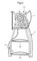
- FIG. 5 shows a conventional worm gearing 35, connected to the cord loop 8, for driving a conventional horizontally-elongated tilt rod 37.
- the tilt rod 37 extends along the longitudinal axis of the head rail 3 and through the tilt swivels 9,11.
- the tilt rod 37 rotates upon movement of the cord loop 8, which makes the worm gearing 35 rotate.
- Such rotation of the tilt rod 37 causes the adjusting pulley 31 and winding drum 34 also to rotate, thereby raising the rear vertical members 17,19 of the ladder 5,7, as well as the auxiliary tilt cords 14,15, so as to open and close the slats 13.
- Internal friction in the worm gearing 35 prevents the tilt rod 37 and thereby the adjusting pulley 31 and winding drum 34 from rotating when the cord loop 8 is not being moved so as to rotate the worm gearing.
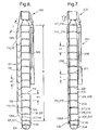
- Figure 6 shows a second embodiment of a blind 101 of the invention which is similar to the blind 1 of Figures 1-5 and for which corresponding reference numerals (greater by 100) are used below for describing the same parts or corresponding parts.
- the blind 101 includes: a horizontally-extending head rail 103; a horizontally-extending bottom rail 104; a pair of vertically-extending ladders 105, 107 (not visible in Fig. 6), each having a rear vertical member 117,119 (not visible in Fig. 6) and a front vertical member 118, 120 (not visible in Fig. 6) and a plurality of cross-rungs 129 between its rear and front, vertical members; and a plurality of slats 113 suspended from the head rail on the cross-rungs.
- a conventional rod-operated tilter 108 attached to compatible gearing (not shown) in the head rail 103, replaces the cord loop 8 and worm gearing 35 of the blind 1 of Figures 1-5.
- a suitable tilter and compatible gearing are described in, for example, WO 98/27307, US 4 541 468, US 3 921 695, US 3 918 513 and US 3 425 479.
- the blind 101 of Figure 6 features additional laterally-extending cross-rungs 130 between each of the rear vertical members 117,119 of the ladders 105, 107 and one of a pair of auxiliary tilt cords 114, 115 (not visible in Fig. 6) which is to the rear of the rear vertical member.
- the auxiliary tilt cords 114, 115 are each connected to a separate tilt swivel (not shown) in the head rail which is connected to, and pivots with a longitudinally-extending tilt rod (not shown) in the head rail that is connected to the gearing of the tilter 108.
- the first pitch P1 between each of the cross-rungs 129 (which connect the rear and front vertical members 117,118 and 119,120 of the ladders 105,107) is slightly greater than the second pitch P2 between each of the additional cross-rungs 130 (which connect the auxiliary tilt cords 114, 115 and the rear vertical member 117,119).
- the auxiliary tilt cords 114, 115 replace the auxiliary tilt cords 14, 15 of the blind 1 of Figures 1-5 and enable the individual slats 113 of the blind 101 to be tilted progressively (rather than by sections of slats as in the blind 1 of Figures 1-5) from the lowermost slat to the uppermost slat, from their normal closed position to an open position, when the auxiliary tilt cords 114, 115 are moved upwardly by twisting the tilter 108.
- the vertical distance, over which the slats 113 are progressively tilted to an open position is determined by the difference between the first pitch P1 of the cross-rungs 129 and the second pitch P2 of the additional cross-rungs 130.
- conventional ladders 105,107 for the venetian blind 101, with 25mm wide slats 113 could normally have a first pitch P1 of 20mm.
- a vertical distance of twenty slats of 25mm lateral width normally corresponds to 400mm of vertical height of the blind 101.
- auxiliary tilt cords 114, 115 of such a blind 101 are raised with all the slats 113 tilted in a normal closed position (i.e., downwardly-inclined from front to rear), then initially the lowest slat 113A will be tilted towards its fully open (i.e., horizontal) position while the nineteen slats (not shown in Fig.
- This side effect of raising the lowermost slat and the bottom rail can be avoided by providing the blind 101 with extra slats 113 and more height, so that all the slats can be opened by moving upwardly the auxiliary tilt cords 114, 115 -- without there being an objectionable light gap underneath the bottom rail 104.
- the number of additional slats 113, required for this purpose, is a function of the ratio between the total height H of the blind 101 and the distance over which its slats 113 are to gradually change their tilt position from normal closed to open.
- the auxiliary tilt cords 114, 115 should be of sufficient lateral length and have sufficient slack so as not to interfere with the basic slat-tilting function of the rear and front, vertical members 117,118 and 119,120 of the ladders 105,107 and their cross-rungs 129. This requires, inter alia, that there be a minimum lateral length L for the additional cross-rungs 130, relative to the height H of the blind 101.
- the minimum length L for the additional crossrungs 130 for a given height H of blind is such that when all of the slats 113 of the blind 101 are in an open (i.e., horizontal) position as shown in Figure 6, the additional cross-rungs 130A, connected to the rear vertical members 117,119 at the lowest slat 113A, extend upwardly from the rear vertical members and the additional cross-rung 130C, connected to the rear vertical members at the uppermost slat 113C, extend downwardly from the rear vertical members.
- each additional cross-rung 130 of the blind 101 should be at least one-half of the total difference in the first and second pitches (i.e., P1 - P2) for the maximum height of the blind 101.
- the minimum length L of each additional cross-rung 130 is thus one-half of the product of the total number of slats 113, corresponding to the maximum height of the blind, times the difference in the first and second pitches.
- the height of the blind 101 is to be a maximum of 2000mm, then with a first pitch (P1) of 20mm, the total number of slats 113 would be one hundred, and with a difference in the first and second pitches (i.e., P1 - P2) of 1mm, the minimum length L of each additional cross-rung would be one-half of 100mm or 50mm.
- P1 - P2 a difference in the first and second pitches
- Figure 7 shows a third embodiment of a blind 201 of the invention which is similar to the blind 101 of Figure 6 and for which corresponding reference numerals (greater by 100) are used below for describing the same parts or corresponding parts.
- the blind 201 includes: a horizontally-extending head rail 203; a horizontally-extending bottom rail 204; a pair of vertically-extending ladders 205, 207 (not visible in Fig. 7), each having a rear vertical member 217,219 (not visible in Fig. 7) and a front vertical member 218, 220 (not visible in Fig. 7) and a plurality of cross-rungs 229 between its rear and front, vertical members; a plurality of slats 213 suspended from the head rail on the cross-rungs; and rod-operated tilter 208, attached to compatible gearing (not shown) in the head rail 203.
- the blind 201 of Figure 7 features a plurality of vertically-aligned tubular elements 230 about each of the rear vertical members 217,219 of the ladders 205,207.
- Each tubular element 230 is between a different pair of vertically adjacent cross-rungs 229 of one of the ladders 205,207 and surrounds a section of the rear vertical member 217, 219 of the ladder between its successive cross-rungs.
- Each tubular element 230 is of a length L that is slightly smaller than the first pitch P1 of the ladders 205,207.
- Each plurality of vertically-aligned tubular elements 230 about one of the rear vertical members 217,219 of the ladders 205,207 also surrounds one of the auxiliary tilt cords 214, 215 (not visible in Fig. 7) to the rear of the one rear vertical member.
- Each auxiliary tilt cord 214, 215 has an engaging knot 240 at its lowermost end which extends downwardly of the lowermost tubular element 230A.
- Each auxiliary tilt cord 214,215 is of sufficient length and has sufficient slack, so as not to interfere with the normal operation of the blind 201.
- the vertical distance, over which the slats 213 are progressively tilted to an open position is determined by the difference between the pitch P1 of the cross-rungs 229 and the length L of the tubular elements 230.
- conventional ladders 205,207 for the venetian blind 201, with 25mm wide slats 213, could normally have a pitch P1 of 20mm.
- a vertical distance of twenty slats of 25mm lateral width normally corresponds to 400mm of vertical height of the blind 201.
- auxiliary tilt cords 214, 215 of such a blind 201 are raised with all the slats 213 tilted in a normal closed position (i.e., downwardly-inclined from front to rear), then initially the lowest slat 213A will be tilted towards its fully open (i.e., horizontal) position while the nineteen slats (not shown in Fig.
- each engaging collar 25 of the blind 1 could be replaced by a clip which has one or more, vertically-extending passages, through which one of the blind's rear vertical members17,19 and its associated auxiliary tilt cord 14,15 or just one of the auxiliary tilt cords pass.
- the collar 25 could also comprise two generally C-shaped halves which could be connected to each other about its associated auxiliary tilt cord 14,15.
- a plurality of collars 25 could be slidably mounted about each auxiliary tilt cord 14,15 and about its associated rear vertical member 17,19, between each adjacent pair of cross-rungs 29 or between selected pairs of cross-rungs of the rear vertical member 17,19.
- Guiding loops 21 are preferably used in the blinds of this invention. However, when no guiding loops are used, both a rear vertical member 17,117,217,19,119,219 and its associated auxiliary tilt cord 14,114,214, 15,115,215 could be within the central passage 27 of each collar 25.
- each auxiliary tilt cord 14,15 of the blind 1 there are preferably only two or three, particularly only two, of the beads 23 and of the engaging collars 25 on each auxiliary tilt cord 14,15 of the blind 1, but there could, if desired, be five to ten of each on each auxiliary tilt cord.
- each tilt swivel 9,11 of the blinds 1,101,201 of this invention can both move the rear and front, vertical members 17,117,217,18,118, 218 and 19,119,219,20,120,220 of one of the ladders 5,105,205,7,107,207 in opposite vertical directions and move vertically the associated auxiliary tilt cord 14,114,214,15,115,215 in response to movement of the cord loop 8 or tilter 108,208.
- rotation of the winding drum 34 of each tilt swivel 9,11 could be controlled by different means (e.g., a separate pull cord connected to the top of both auxiliary tilt cords) from the cord loop or tilter which controls rotation of the adjusting pulley 31.
- Such separate means would allow lower portions of the blind, when fully open, to be selectively closed by simply actuating such separate means to pull both auxiliary tilt cords upwardly.
- the normal closed position of the slats 13,113,213 of the blinds 1,101,201 could alternatively be downwardly-inclined from rear to front, and the abnormal closed position of the blind could be downwardly-inclined from front to rear.
- a blind of this invention could have the ladders 5,7 of the blind 1 with their regularly spaced guiding loops 21 and also have the auxiliary tilt cords 14,15 of the blind 1, extending through the guiding loops but have the tubular elements 230 of the blind 201 only on each auxiliary tilt cord between pairs of vertically adjacent loops.
- the length L of the tubular elements would be smaller than the second pitch P2 of the loops and have a predefined relation to the first pitch P1 of the cross-rungs of the ladders.
- a blind of this invention could have a single common winding drum for the auxiliary tilt cords 14,114,214,15,115,215, which would not be operatively connected with the tilt swivels 9,11 of the ladders 5,105,205, 7,107,207 but would be operate by a separate manually operable cord loop .
- a conventional, downwardly-extending, spacer bracket (not shown) could be mounted on the rear of the head rail 3,103,203 of a blind of this invention, adjacent the point of entry of each auxiliary tilt cord 14,114,214,15, 115,215 into the bottom of the head rail.
- the bracket could thereby serve to route the auxiliary tilt cord rearwardly of the bracket before the tilt cord enters the head rail, to keep it from rubbing against the adjacent rear vertical member 17,117,217, 19,119,219 where they both enter the head rail.
Landscapes
- Engineering & Computer Science (AREA)
- Structural Engineering (AREA)
- Architecture (AREA)
- Civil Engineering (AREA)
- Blinds (AREA)
- Operating, Guiding And Securing Of Roll- Type Closing Members (AREA)
Priority Applications (1)
| Application Number | Priority Date | Filing Date | Title |
|---|---|---|---|
| EP01304392A EP1156182B1 (en) | 2000-05-19 | 2001-05-17 | Venetian blind with variable tilting |
Applications Claiming Priority (3)
| Application Number | Priority Date | Filing Date | Title |
|---|---|---|---|
| EP00201769 | 2000-05-19 | ||
| EP00201769 | 2000-05-19 | ||
| EP01304392A EP1156182B1 (en) | 2000-05-19 | 2001-05-17 | Venetian blind with variable tilting |
Publications (3)
| Publication Number | Publication Date |
|---|---|
| EP1156182A2 EP1156182A2 (en) | 2001-11-21 |
| EP1156182A3 EP1156182A3 (en) | 2002-05-29 |
| EP1156182B1 true EP1156182B1 (en) | 2007-02-21 |
Family
ID=8171514
Family Applications (1)
| Application Number | Title | Priority Date | Filing Date |
|---|---|---|---|
| EP01304392A Expired - Lifetime EP1156182B1 (en) | 2000-05-19 | 2001-05-17 | Venetian blind with variable tilting |
Country Status (11)
| Country | Link |
|---|---|
| US (2) | US6422288B1 (pt) |
| EP (1) | EP1156182B1 (pt) |
| JP (1) | JP5084994B2 (pt) |
| AR (1) | AR035398A1 (pt) |
| AT (1) | ATE354715T1 (pt) |
| AU (1) | AU777834B2 (pt) |
| BR (1) | BR0102058B1 (pt) |
| CA (1) | CA2348043C (pt) |
| DE (1) | DE60126705T2 (pt) |
| DK (1) | DK1156182T3 (pt) |
| MX (1) | MXPA01004922A (pt) |
Families Citing this family (25)
| Publication number | Priority date | Publication date | Assignee | Title |
|---|---|---|---|---|
| US6845802B1 (en) | 2001-08-15 | 2005-01-25 | Hunter Douglas Inc. | Selective tilting arrangement for a blind system for coverings for architectural openings |
| DE20219865U1 (de) * | 2002-12-21 | 2003-03-06 | Mhz Hachtel & Co | Horizontal-Jalousie |
| CA2473426A1 (en) * | 2003-10-20 | 2005-04-20 | Zhengxiong Su | A window blind |
| US20070006981A1 (en) * | 2004-05-16 | 2007-01-11 | Ker-Min Lin | Window blind with hollow slats |
| US7806030B2 (en) * | 2005-06-29 | 2010-10-05 | Lumino, Inc. | Cutting machine for blinds |
| US7913738B2 (en) | 2005-09-02 | 2011-03-29 | Hunter Douglas Inc. | Selective tilting for blinds—variable radius wrap double pitch |
| US7760984B2 (en) * | 2006-05-04 | 2010-07-20 | Adc Telecommunications, Inc. | Fiber distribution hub with swing frame and wrap-around doors |
| US8267145B2 (en) * | 2007-05-31 | 2012-09-18 | Hunter Douglas Inc. | Blind with selective tilting arrangement including drums |
| CN101392624B (zh) * | 2007-09-21 | 2012-07-04 | 赖国栋 | 复式叶片窗帘放大之控轴 |
| US20100071858A1 (en) * | 2008-09-23 | 2010-03-25 | Tony Lai | Window blind with controlling axle |
| US9649774B2 (en) * | 2009-01-06 | 2017-05-16 | Lumino, Inc. | Method and machine for cutting blinds |
| US8739666B2 (en) * | 2009-01-07 | 2014-06-03 | Lumino, Inc. | Window covering cutting machine |
| EP2545240A2 (en) * | 2010-03-10 | 2013-01-16 | Jørn Krab Holding APS | A flexible venetian blind |
| US9091115B2 (en) | 2010-10-18 | 2015-07-28 | Qmotion Incorporated | Motorizable tilt shade system and method |
| CN104254660B (zh) | 2012-02-27 | 2016-08-24 | 亨特道格拉斯工业公司 | 百叶窗倾斜总成和控制倾斜梯格的方法 |
| GB2534083B (en) * | 2013-10-01 | 2019-10-16 | Hunter Douglas Ind Bv | Rail for an architectural covering |
| CN203626568U (zh) * | 2013-11-20 | 2014-06-04 | 周隽 | 百叶窗 |
| US20170030141A1 (en) * | 2015-07-28 | 2017-02-02 | Robert Marion Cato | Window Blind Clips and Method of Use |
| CN108661531B (zh) * | 2017-03-30 | 2020-05-19 | 陈金福 | 窗帘 |
| EP3409875A1 (en) | 2017-06-01 | 2018-12-05 | Hunter Douglas Industries B.V. | Tilt adjuster control mechanism for a venetian blind |
| CN109424308B (zh) * | 2017-09-05 | 2020-07-10 | 亿丰综合工业股份有限公司 | 百叶窗帘 |
| US10676988B2 (en) * | 2017-09-20 | 2020-06-09 | Whole Space Industries Ltd. | Window covering control apparatus |
| AU2018253645A1 (en) * | 2017-10-31 | 2019-05-16 | Hunter Douglas Industries B.V. | Control mechanism for a double pitch blind and a double pitch blind assembly |
| US11492844B2 (en) * | 2021-01-15 | 2022-11-08 | Sheen World Technology Corporation | Venetian blind capable of facilitating inclination angle adjustment of slats |
| USD1025654S1 (en) * | 2023-08-17 | 2024-05-07 | Changzhou Qiaokang Decoration Materials Co., Ltd | Blind |
Family Cites Families (25)
| Publication number | Priority date | Publication date | Assignee | Title |
|---|---|---|---|---|
| DE134151C (pt) | 1901-08-21 | |||
| US1365919A (en) | 1919-08-27 | 1921-01-18 | Jones Bevan | Louver-blind |
| US2116356A (en) | 1937-06-19 | 1938-05-03 | Laborda Richard | Venetian blind |
| US2506507A (en) | 1945-12-04 | 1950-05-02 | Kiatta Nicholas Haleem | Venetian blind |
| US2427266A (en) | 1945-12-06 | 1947-09-09 | Ewing Edgar Gill | Venetian blind |
| US2719586A (en) | 1952-11-21 | 1955-10-04 | George M Graham | Tilt device for venetian blinds |
| US2751000A (en) | 1953-10-12 | 1956-06-19 | James A Anderson | Venetian blind |
| US2747662A (en) | 1954-01-11 | 1956-05-29 | Herbert H Reiners | Venetian blind |
| DE1509494A1 (de) | 1964-10-20 | 1969-05-14 | Hedberg Klas Wilhelm Rune | Einstellvorrichtung fuer Lamellenjalousien |
| AU410797B2 (en) | 1967-01-26 | 1971-02-17 | Theodore Webb Barrie | Improvements in venetian blinds |
| NL155911B (nl) | 1968-09-19 | 1978-02-15 | Silverflex Int Nv | Bedieningsinrichting voor een jaloezie. |
| JPS6355595A (ja) | 1987-05-21 | 1988-03-10 | ヤマハ株式会社 | 電子楽器の自動伴奏装置 |
| US4940070A (en) | 1988-03-29 | 1990-07-10 | Warden Scott L | Bifold privacy miniblind |
| US4921032A (en) | 1988-12-02 | 1990-05-01 | Appropriate Technology Corporation | Roman shades |
| CH687035A5 (de) | 1993-01-18 | 1996-08-30 | Schenker Storen Ag | Rafflamellenstore. |
| JPH0671888U (ja) | 1993-03-22 | 1994-10-07 | 有限会社プロメ | 可変式横形ブラインド |
| US5485874A (en) * | 1994-04-18 | 1996-01-23 | Whitmore; William F. | Venetian blind |
| US5472035A (en) | 1994-06-27 | 1995-12-05 | Springs Window Fashions Division, Inc. | Window blind with wand operator |
| GB2292578B (en) | 1994-08-11 | 1997-12-10 | Eclipse Blinds Ltd | Pleated blinds |
| JPH08210060A (ja) | 1995-01-31 | 1996-08-13 | Masateru Hasemi | ブラインド |
| JPH0921282A (ja) | 1995-07-06 | 1997-01-21 | Kaizo Maeda | ブラインドの羽根任意上下別角度変更装置 |
| CA2274229C (en) | 1996-12-18 | 2005-07-26 | Hunter Douglas Inc. | Control wand for coverings for architectural openings |
| IL124778A0 (en) * | 1997-06-24 | 1999-01-26 | Holis Metal Ind Ltd | Tilting mechanism for a venetian blind |
| US6105652A (en) * | 1998-11-23 | 2000-08-22 | Judkins; Ren | Venetian type blind having separately tilting slat sections |
| US6318439B1 (en) * | 1999-03-24 | 2001-11-20 | The Akasaka Kogei Co., Ltd. | Blind with portions selectable for introducing or shielding light |
-
2001
- 2001-05-10 US US09/853,952 patent/US6422288B1/en not_active Ceased
- 2001-05-16 MX MXPA01004922A patent/MXPA01004922A/es active IP Right Grant
- 2001-05-17 EP EP01304392A patent/EP1156182B1/en not_active Expired - Lifetime
- 2001-05-17 DK DK01304392T patent/DK1156182T3/da active
- 2001-05-17 CA CA002348043A patent/CA2348043C/en not_active Expired - Lifetime
- 2001-05-17 DE DE60126705T patent/DE60126705T2/de not_active Expired - Lifetime
- 2001-05-17 AT AT01304392T patent/ATE354715T1/de active
- 2001-05-18 AR ARP010102377A patent/AR035398A1/es active IP Right Grant
- 2001-05-18 JP JP2001149925A patent/JP5084994B2/ja not_active Expired - Lifetime
- 2001-05-18 AU AU46145/01A patent/AU777834B2/en not_active Expired
- 2001-05-21 BR BRPI0102058-7A patent/BR0102058B1/pt not_active IP Right Cessation
-
2003
- 2003-07-21 US US10/624,938 patent/USRE43475E1/en not_active Expired - Lifetime
Also Published As
| Publication number | Publication date |
|---|---|
| MXPA01004922A (es) | 2004-04-21 |
| DK1156182T3 (da) | 2007-06-18 |
| USRE43475E1 (en) | 2012-06-19 |
| AU777834B2 (en) | 2004-11-04 |
| JP2002070460A (ja) | 2002-03-08 |
| ATE354715T1 (de) | 2007-03-15 |
| BR0102058A (pt) | 2001-12-18 |
| AR035398A1 (es) | 2004-05-26 |
| EP1156182A3 (en) | 2002-05-29 |
| DE60126705D1 (de) | 2007-04-05 |
| CA2348043A1 (en) | 2001-11-19 |
| US6422288B1 (en) | 2002-07-23 |
| EP1156182A2 (en) | 2001-11-21 |
| AU4614501A (en) | 2001-11-22 |
| BR0102058B1 (pt) | 2009-08-11 |
| CA2348043C (en) | 2008-09-16 |
| US20020020506A1 (en) | 2002-02-21 |
| DE60126705T2 (de) | 2007-11-08 |
| JP5084994B2 (ja) | 2012-11-28 |
Similar Documents
| Publication | Publication Date | Title |
|---|---|---|
| EP1156182B1 (en) | Venetian blind with variable tilting | |
| AU2007201248B2 (en) | Suspension system for a cordless window covering | |
| US5497820A (en) | Blind tilt actuator | |
| EP1061839B1 (en) | View-through cellular window covering | |
| US5060709A (en) | Infinitely sizable solid slat mini blind | |
| CA2409802C (en) | Combination blind with multiple shading sections | |
| US5839494A (en) | Bottom and top stacking venetian type blind with fixed headrail tilt | |
| US10550635B2 (en) | Window covering control apparatus | |
| US6105652A (en) | Venetian type blind having separately tilting slat sections | |
| US7100663B2 (en) | Window covering and method of use | |
| EP1219776B1 (en) | Ladder operated covering with fixed vanes for architectural openings | |
| US20140238622A1 (en) | Systems and methods for tilting a blind slat | |
| US10676988B2 (en) | Window covering control apparatus | |
| US7100664B2 (en) | Blind slat control mechanism | |
| US5316066A (en) | Cord-lock mechanism | |
| JP6473313B2 (ja) | 遮蔽装置 | |
| EP1571289A1 (en) | Counterbalanced stacking blind | |
| JPH0842268A (ja) | 上下独立型ブラインド | |
| US20210017813A1 (en) | Combination horizontal blind ladder and operating cable | |
| KR200363365Y1 (ko) | 블라인드 | |
| JP6893768B2 (ja) | 横型ブラインド | |
| KR101863242B1 (ko) | 수평블라인드용 다목적 슬래트 방향전환 및 기울기 조절장치 | |
| JP2004108045A (ja) | 分段型ブラインド | |
| JP2004143918A (ja) | ベネチアン・ブラインドのための引き上げ機構 | |
| JP6479413B2 (ja) | 昇降コード支持装置及び遮蔽装置 |
Legal Events
| Date | Code | Title | Description |
|---|---|---|---|
| PUAI | Public reference made under article 153(3) epc to a published international application that has entered the european phase |
Free format text: ORIGINAL CODE: 0009012 |
|
| AK | Designated contracting states |
Kind code of ref document: A2 Designated state(s): AT BE CH CY DE DK ES FI FR GB GR IE IT LI LU MC NL PT SE TR |
|
| AX | Request for extension of the european patent |
Free format text: AL;LT;LV;MK;RO;SI |
|
| RIC1 | Information provided on ipc code assigned before grant |
Free format text: 7E 06B 9/307 A, 7E 06B 9/38 B |
|
| PUAL | Search report despatched |
Free format text: ORIGINAL CODE: 0009013 |
|
| AK | Designated contracting states |
Kind code of ref document: A3 Designated state(s): AT BE CH CY DE DK ES FI FR GB GR IE IT LI LU MC NL PT SE TR |
|
| AX | Request for extension of the european patent |
Free format text: AL;LT;LV;MK;RO;SI |
|
| 17P | Request for examination filed |
Effective date: 20020702 |
|
| AKX | Designation fees paid |
Designated state(s): AT BE CH CY DE DK ES FI FR GB GR IE IT LI LU MC NL PT SE TR |
|
| GRAJ | Information related to disapproval of communication of intention to grant by the applicant or resumption of examination proceedings by the epo deleted |
Free format text: ORIGINAL CODE: EPIDOSDIGR1 |
|
| GRAP | Despatch of communication of intention to grant a patent |
Free format text: ORIGINAL CODE: EPIDOSNIGR1 |
|
| GRAS | Grant fee paid |
Free format text: ORIGINAL CODE: EPIDOSNIGR3 |
|
| GRAA | (expected) grant |
Free format text: ORIGINAL CODE: 0009210 |
|
| AK | Designated contracting states |
Kind code of ref document: B1 Designated state(s): AT BE CH CY DE DK ES FI FR GB GR IE IT LI LU MC NL PT SE TR |
|
| PG25 | Lapsed in a contracting state [announced via postgrant information from national office to epo] |
Ref country code: FI Free format text: LAPSE BECAUSE OF FAILURE TO SUBMIT A TRANSLATION OF THE DESCRIPTION OR TO PAY THE FEE WITHIN THE PRESCRIBED TIME-LIMIT Effective date: 20070221 |
|
| REG | Reference to a national code |
Ref country code: GB Ref legal event code: FG4D |
|
| REG | Reference to a national code |
Ref country code: CH Ref legal event code: EP |
|
| REF | Corresponds to: |
Ref document number: 60126705 Country of ref document: DE Date of ref document: 20070405 Kind code of ref document: P |
|
| REG | Reference to a national code |
Ref country code: IE Ref legal event code: FG4D |
|
| REG | Reference to a national code |
Ref country code: CH Ref legal event code: NV Representative=s name: ROTTMANN, ZIMMERMANN + PARTNER AG |
|
| REG | Reference to a national code |
Ref country code: SE Ref legal event code: TRGR |
|
| PG25 | Lapsed in a contracting state [announced via postgrant information from national office to epo] |
Ref country code: ES Free format text: LAPSE BECAUSE OF FAILURE TO SUBMIT A TRANSLATION OF THE DESCRIPTION OR TO PAY THE FEE WITHIN THE PRESCRIBED TIME-LIMIT Effective date: 20070601 |
|
| REG | Reference to a national code |
Ref country code: DK Ref legal event code: T3 |
|
| PG25 | Lapsed in a contracting state [announced via postgrant information from national office to epo] |
Ref country code: PT Free format text: LAPSE BECAUSE OF FAILURE TO SUBMIT A TRANSLATION OF THE DESCRIPTION OR TO PAY THE FEE WITHIN THE PRESCRIBED TIME-LIMIT Effective date: 20070723 |
|
| ET | Fr: translation filed | ||
| PLBE | No opposition filed within time limit |
Free format text: ORIGINAL CODE: 0009261 |
|
| STAA | Information on the status of an ep patent application or granted ep patent |
Free format text: STATUS: NO OPPOSITION FILED WITHIN TIME LIMIT |
|
| 26N | No opposition filed |
Effective date: 20071122 |
|
| PG25 | Lapsed in a contracting state [announced via postgrant information from national office to epo] |
Ref country code: MC Free format text: LAPSE BECAUSE OF NON-PAYMENT OF DUE FEES Effective date: 20070531 |
|
| PG25 | Lapsed in a contracting state [announced via postgrant information from national office to epo] |
Ref country code: GR Free format text: LAPSE BECAUSE OF FAILURE TO SUBMIT A TRANSLATION OF THE DESCRIPTION OR TO PAY THE FEE WITHIN THE PRESCRIBED TIME-LIMIT Effective date: 20070522 |
|
| PG25 | Lapsed in a contracting state [announced via postgrant information from national office to epo] |
Ref country code: IE Free format text: LAPSE BECAUSE OF NON-PAYMENT OF DUE FEES Effective date: 20070517 |
|
| PG25 | Lapsed in a contracting state [announced via postgrant information from national office to epo] |
Ref country code: CY Free format text: LAPSE BECAUSE OF FAILURE TO SUBMIT A TRANSLATION OF THE DESCRIPTION OR TO PAY THE FEE WITHIN THE PRESCRIBED TIME-LIMIT Effective date: 20070221 |
|
| PG25 | Lapsed in a contracting state [announced via postgrant information from national office to epo] |
Ref country code: LU Free format text: LAPSE BECAUSE OF NON-PAYMENT OF DUE FEES Effective date: 20070517 |
|
| PG25 | Lapsed in a contracting state [announced via postgrant information from national office to epo] |
Ref country code: TR Free format text: LAPSE BECAUSE OF FAILURE TO SUBMIT A TRANSLATION OF THE DESCRIPTION OR TO PAY THE FEE WITHIN THE PRESCRIBED TIME-LIMIT Effective date: 20070221 |
|
| REG | Reference to a national code |
Ref country code: CH Ref legal event code: PFA Owner name: HUNTER DOUGLAS INDUSTRIES B.V. Free format text: HUNTER DOUGLAS INDUSTRIES B.V.#PIEKSTRAAT 2#3071 EL ROTTERDAM (NL) -TRANSFER TO- HUNTER DOUGLAS INDUSTRIES B.V.#PIEKSTRAAT 2#3071 EL ROTTERDAM (NL) |
|
| REG | Reference to a national code |
Ref country code: FR Ref legal event code: PLFP Year of fee payment: 15 |
|
| REG | Reference to a national code |
Ref country code: FR Ref legal event code: PLFP Year of fee payment: 16 |
|
| REG | Reference to a national code |
Ref country code: CH Ref legal event code: PCAR Free format text: NEW ADDRESS: GARTENSTRASSE 28 A, 5400 BADEN (CH) |
|
| REG | Reference to a national code |
Ref country code: FR Ref legal event code: PLFP Year of fee payment: 17 |
|
| REG | Reference to a national code |
Ref country code: FR Ref legal event code: PLFP Year of fee payment: 18 |
|
| PGFP | Annual fee paid to national office [announced via postgrant information from national office to epo] |
Ref country code: DK Payment date: 20200512 Year of fee payment: 20 Ref country code: DE Payment date: 20200506 Year of fee payment: 20 Ref country code: FR Payment date: 20200414 Year of fee payment: 20 Ref country code: CH Payment date: 20200515 Year of fee payment: 20 Ref country code: NL Payment date: 20200513 Year of fee payment: 20 |
|
| PGFP | Annual fee paid to national office [announced via postgrant information from national office to epo] |
Ref country code: IT Payment date: 20200414 Year of fee payment: 20 Ref country code: GB Payment date: 20200506 Year of fee payment: 20 Ref country code: SE Payment date: 20200512 Year of fee payment: 20 Ref country code: BE Payment date: 20200416 Year of fee payment: 20 |
|
| PGFP | Annual fee paid to national office [announced via postgrant information from national office to epo] |
Ref country code: AT Payment date: 20200428 Year of fee payment: 20 |
|
| REG | Reference to a national code |
Ref country code: DE Ref legal event code: R071 Ref document number: 60126705 Country of ref document: DE |
|
| REG | Reference to a national code |
Ref country code: NL Ref legal event code: MK Effective date: 20210516 |
|
| REG | Reference to a national code |
Ref country code: DK Ref legal event code: EUP Expiry date: 20210517 |
|
| REG | Reference to a national code |
Ref country code: CH Ref legal event code: PL |
|
| REG | Reference to a national code |
Ref country code: GB Ref legal event code: PE20 Expiry date: 20210516 |
|
| REG | Reference to a national code |
Ref country code: BE Ref legal event code: MK Effective date: 20210517 |
|
| REG | Reference to a national code |
Ref country code: SE Ref legal event code: EUG |
|
| REG | Reference to a national code |
Ref country code: AT Ref legal event code: MK07 Ref document number: 354715 Country of ref document: AT Kind code of ref document: T Effective date: 20210517 |
|
| PG25 | Lapsed in a contracting state [announced via postgrant information from national office to epo] |
Ref country code: GB Free format text: LAPSE BECAUSE OF EXPIRATION OF PROTECTION Effective date: 20210516 |