EP1155947A1 - Combined stand and anti-theft devices for a bicycle - Google Patents
Combined stand and anti-theft devices for a bicycle Download PDFInfo
- Publication number
- EP1155947A1 EP1155947A1 EP00500093A EP00500093A EP1155947A1 EP 1155947 A1 EP1155947 A1 EP 1155947A1 EP 00500093 A EP00500093 A EP 00500093A EP 00500093 A EP00500093 A EP 00500093A EP 1155947 A1 EP1155947 A1 EP 1155947A1
- Authority
- EP
- European Patent Office
- Prior art keywords
- parking
- locking
- frame
- fork
- unfolded
- Prior art date
- Legal status (The legal status is an assumption and is not a legal conclusion. Google has not performed a legal analysis and makes no representation as to the accuracy of the status listed.)
- Withdrawn
Links
Images


Classifications
-
- B—PERFORMING OPERATIONS; TRANSPORTING
- B62—LAND VEHICLES FOR TRAVELLING OTHERWISE THAN ON RAILS
- B62H—CYCLE STANDS; SUPPORTS OR HOLDERS FOR PARKING OR STORING CYCLES; APPLIANCES PREVENTING OR INDICATING UNAUTHORIZED USE OR THEFT OF CYCLES; LOCKS INTEGRAL WITH CYCLES; DEVICES FOR LEARNING TO RIDE CYCLES
- B62H5/00—Appliances preventing or indicating unauthorised use or theft of cycles; Locks integral with cycles
- B62H5/005—Appliances preventing or indicating unauthorised use or theft of cycles; Locks integral with cycles acting on the stand
-
- B—PERFORMING OPERATIONS; TRANSPORTING
- B62—LAND VEHICLES FOR TRAVELLING OTHERWISE THAN ON RAILS
- B62H—CYCLE STANDS; SUPPORTS OR HOLDERS FOR PARKING OR STORING CYCLES; APPLIANCES PREVENTING OR INDICATING UNAUTHORIZED USE OR THEFT OF CYCLES; LOCKS INTEGRAL WITH CYCLES; DEVICES FOR LEARNING TO RIDE CYCLES
- B62H1/00—Supports or stands forming part of or attached to cycles
- B62H1/06—Extensible stands, e.g. with telescopic parts
-
- B—PERFORMING OPERATIONS; TRANSPORTING
- B62—LAND VEHICLES FOR TRAVELLING OTHERWISE THAN ON RAILS
- B62H—CYCLE STANDS; SUPPORTS OR HOLDERS FOR PARKING OR STORING CYCLES; APPLIANCES PREVENTING OR INDICATING UNAUTHORIZED USE OR THEFT OF CYCLES; LOCKS INTEGRAL WITH CYCLES; DEVICES FOR LEARNING TO RIDE CYCLES
- B62H5/00—Appliances preventing or indicating unauthorised use or theft of cycles; Locks integral with cycles
- B62H5/14—Appliances preventing or indicating unauthorised use or theft of cycles; Locks integral with cycles preventing wheel rotation
- B62H5/142—Appliances preventing or indicating unauthorised use or theft of cycles; Locks integral with cycles preventing wheel rotation by means of pivoting, or pivoting and sliding bolts
Definitions
- the present invention is a parking and parking system. lock for bicycles or other.
- the system which is the subject of the invention advantageously replaces the anti-theft devices and support devices that are currently required bicycles (and in general, mopeds, small motorcycles displacement structured on a frame or chassis with two wheels) to park them and leave them unattended.
- the stand / support is a manual assisted system and the anti-theft device is independent of its own cycle.
- the objective of the present invention is to provide the cycle with a parking device and a locking device, forming a unit inseparable united to the frame of the cycle.
- parking and blocking devices act synchronized, folding with respect to the frame simultaneously. For fold or unfold them, the user has mechanisms that can be activated and blocked by a locking system.
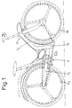
- Figure 1 shows a general elevation view of a cycle which is equipped with the parking and blocking system according to the invention.
- This system shows the system in the folded position - cycle in the use position - its components such as the wheels (R 1 ), (R 2 ), the saddle, the pedals, the handlebars, etc. are dotted.
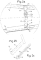
- Figures 2 represent a very enlarged detail on plan-figure 2a- of the locking device (2) in the operational position of rest (unfolded) and in elevation -figure 2b- and on plan -figure 2c- the mechanisms for separate operation in position corresponding to this situation.
- Figures 3a, 3b, 3c show the same details in the same position as FIGS. 2a, 2b, 2c corresponding here to the position operational use (folded).
- Figures 4 show very enlarged details in elevation -figure 4a- of the parking device (1) in position operational rest (unfolded) with a partial view - figure 4b- at 90 ° by compared to the front, to observe the position of the stand (1) with the action of the spring (14) and a plan view -figure 4c- of the mechanisms for separate operation in the position corresponding to this situation.
- Figures 5a and 5b show the same details as the previous figures 4a, 4c, corresponding here to the operational position of use.
- the parking device (1) is placed - see Figure 1- relative to the tubing (t 1 ) of the frame (C) into which it enters by folding it.
- the locking device (2) is placed relative to the forks (t 2 ) of the frame (C) bending against one of them (half hidden) - see Figure 3a- and forming a practically orthogonal angle on the two forks (t 2 ) and (t ' 2 ) of the frame (C) - see figure 2a- crossing one of the wheels (R 2 ) when it is used.
- the mechanisms (3) for separately using the parking (1) and locking (2) devices are in a tubular area (t 3 ) of the frame - see Figure 1, moving linearly between two extreme positions, guided in a groove (3a) formed in the own tubing (t 3 ).
- the stand / support (11) is articulated (15) on the internal support (12). There is a spring (14) which abuts against the stand (11) and the support (12) keeps them in a turned / unfolded position.
- the tensioner / regulator (13) which is for example a plate or a strip, permanently connects the internal support (12) to a second internal support (32) belonging to the mechanisms (3) described below.
- the arm (21) is articulated on (24) on a fork (t 2 ) of the frame. This fork (t 2 ) is open laterally. There is a spring (25) which abuts against the fork (t 2 ) and the arm (21) keeps them in a turned / unfolded position.
- the pawl (22) is located inside the arm (21) where it is guided for example by a groove (22a) where an axis (21a) moves between the two ends, formed by the groove (22 a) of the pawl (22) and the rod (21a) of the arm (21) or vice versa.
- the pawl (22) is provided with a tensioner (23) and is kept in unfolded position under the action of a spring (26) -see figure 2a-.
- the tensioner (23) which is for example a traction cable connects permanently the pawl (22) and the internal support (32) belonging to mechanisms (3) which are described below.
- the guide groove (3a) is formed in the corresponding tubing (t 3 ) of the frame (C).
- the external head (31) and the internal support (32) are connected by this guide groove (3a) where they move.
- the closure (33) on the head (31) blocks the assembly in an extreme position introducing the lock into a hole (O 1 ) opposite, in the axis and in the guide groove (3a).
- the length of the guide groove (3a) is such that the position described corresponds to the position of the arm (21) unfolded and the projecting part of the pawl (22) housed in an orifice (0 2 ) of the fork (t ' 2 ) and with the stand / support position (11) unfolded.
Landscapes
- Engineering & Computer Science (AREA)
- Mechanical Engineering (AREA)
- Motorcycle And Bicycle Frame (AREA)
Abstract
Description
La présente invention est un système de stationnement et de blocage pour bicyclettes ou autres.The present invention is a parking and parking system. lock for bicycles or other.
Le système, objet de l'invention, remplace avantageusement les dispositifs antivol et les dispositifs de soutien que requièrent actuellement les bicyclettes (et en général, les cyclomoteurs, les motocyclettes de petite cylindrée structurées sur un cadre ou un châssis à deux roues) pour les garer et les laisser sans surveillance.The system which is the subject of the invention advantageously replaces the anti-theft devices and support devices that are currently required bicycles (and in general, mopeds, small motorcycles displacement structured on a frame or chassis with two wheels) to park them and leave them unattended.
La mention «cycle» qui apparaít tout au long de ce dossier se réfère à un type de véhicules à deux roues où l'invention est applicable.The mention "cycle" that appears throughout this file is refers to a type of two-wheeled vehicle where the invention is applicable.
Ces cycles requièrent généralement une béquille, servant de troisième point d'appui quand ils sont garés. De plus, ils ont besoin d'un dispositif antivol pour bloquer au moins le fonctionnement d'une roue.These cycles generally require a crutch, serving as third point of support when they are parked. In addition, they need a anti-theft device to block at least one wheel operation.
En général, la béquille/soutien est un système manuel assisté et le dispositif antivol est indépendant du propre cycle.In general, the stand / support is a manual assisted system and the anti-theft device is independent of its own cycle.
L'objectif de la présente invention est de doter le cycle d'un dispositif de stationnement et d'un dispositif de blocage, formant une unité inséparable uni au cadre du cycle.The objective of the present invention is to provide the cycle with a parking device and a locking device, forming a unit inseparable united to the frame of the cycle.
Ces dispositifs de stationnement et de blocage agissent de façon synchronisée, se pliant par rapport au cadre de façon simultanée. Pour les plier ou les déplier, l'usager dispose de mécanismes pouvant être actionnés et bloqués par un système de verrouillage.These parking and blocking devices act synchronized, folding with respect to the frame simultaneously. For fold or unfold them, the user has mechanisms that can be activated and blocked by a locking system.
Selon le système de stationnement et de blocage pour
bicyclettes ou autres, objet de l'invention, par rapport au cadre du cycle, on
dispose de:
En particulier:
Pour mieux comprendre l'objet de la présente invention, un exemple de réalisation pratique est représentée sur les plans, susceptible de changements accessoires mais qui ne trahiront pas l'idée de base.To better understand the object of the present invention, a practical example is shown on the plans, likely to incidental changes but which will not betray the basic idea.
La figure 1 représente une vue générale en élévation d'un cycle qui est équipé du système de stationnement et de blocage selon l'invention.Figure 1 shows a general elevation view of a cycle which is equipped with the parking and blocking system according to the invention.
On a représenté sur cette figure le système en position plié - cycle en position d'utilisation - ses composants tels que les roues (R1), (R2), la selle, les pédales, le guidon, etc. sont en pointillés.This system shows the system in the folded position - cycle in the use position - its components such as the wheels (R 1 ), (R 2 ), the saddle, the pedals, the handlebars, etc. are dotted.
Les figures 2 représentent un détail très agrandi sur plan-figure 2a- du dispositif de blocage (2) en position opérationnelle de repos (déplié) et en élévation -figure 2b- et sur plan -figure 2c- les mécanismes pour un fonctionnement séparé en position correspondant à cette situation.Figures 2 represent a very enlarged detail on plan-figure 2a- of the locking device (2) in the operational position of rest (unfolded) and in elevation -figure 2b- and on plan -figure 2c- the mechanisms for separate operation in position corresponding to this situation.
Les figures 3a, 3b, 3c représentent les mêmes détails dans la même position que les figures 2a, 2b, 2c correspondant ici à la position opérationnelle d'utilisation (plié).Figures 3a, 3b, 3c show the same details in the same position as FIGS. 2a, 2b, 2c corresponding here to the position operational use (folded).
Les figures 4 représentent des détails très agrandis en élévation -figure 4a- du dispositif de stationnement (1) en position opérationnelle de repos (déplié) avec une vue partielle - figure 4b- à 90° par rapport à l'antérieure, pour observer la position de la béquille (1) avec l'action du ressort (14) et une vue sur plan -figure 4c- des mécanismes pour un fonctionnement séparé sur la position correspondant à cette situation.Figures 4 show very enlarged details in elevation -figure 4a- of the parking device (1) in position operational rest (unfolded) with a partial view - figure 4b- at 90 ° by compared to the front, to observe the position of the stand (1) with the action of the spring (14) and a plan view -figure 4c- of the mechanisms for separate operation in the position corresponding to this situation.
Les figures 5a et 5b représentent les mêmes détails que les figures 4a, 4c antérieures, correspondant ici à la position opérationnelle d'utilisation.Figures 5a and 5b show the same details as the previous figures 4a, 4c, corresponding here to the operational position of use.
Voici un exemple de réalisation pratique, non limitative, de la présente invention. Here is an example of practical, non-limiting embodiment of the present invention.
Il s'agit d'un système de stationnement et de blocage pour bicyclettes ou autres, -cycles en général- qui sont composés d'un cadre (C) formé par des tubulures où se trouvent deux roues (R1), (R2).It is a parking and locking system for bicycles or other, -cycles in general- which are composed of a frame (C) formed by pipes where there are two wheels (R 1 ), (R 2 ).
Selon l'invention, on pose par rapport au cadre (C) du cycle un dispositif de stationnement (1) et un dispositif de blocage (2) et de mécanismes (3) pour les actionner de façon séparée et synchronisée.According to the invention, one poses with respect to the frame (C) of the cycle a parking device (1) and a locking device (2) and mechanisms (3) for actuating them separately and synchronized.
Le dispositif de stationnement (1) est posé -voir figure 1- par rapport à la tubulure (t1) du cadre (C) dans laquelle il rentre en le pliant.The parking device (1) is placed - see Figure 1- relative to the tubing (t 1 ) of the frame (C) into which it enters by folding it.
Le dispositif de blocage (2) est posé par rapport aux fourches (t2) du cadre (C) se pliant contre l'une d'elles (à moitié caché) - voir figure 3a- et formant un angle pratiquement orthogonal sur les deux fourches (t2) et (t'2) du cadre (C) - voir figure 2a- traversant une des roues (R2) quand il est utilisé.The locking device (2) is placed relative to the forks (t 2 ) of the frame (C) bending against one of them (half hidden) - see Figure 3a- and forming a practically orthogonal angle on the two forks (t 2 ) and (t ' 2 ) of the frame (C) - see figure 2a- crossing one of the wheels (R 2 ) when it is used.
Les mécanismes (3) pour utiliser séparément les dispositifs de stationnement (1) et de blocage (2) sont dans une zone tubulaire (t3) du cadre - voir figure 1, se déplaçant de façon linéaire entre deux positions extrêmes, guidés dans une rainure (3a) formée dans la propre tubulure (t3).The mechanisms (3) for separately using the parking (1) and locking (2) devices are in a tubular area (t 3 ) of the frame - see Figure 1, moving linearly between two extreme positions, guided in a groove (3a) formed in the own tubing (t 3 ).
Pour la réalisation représentée, le dispositif de stationnement (1) est composé de:
- une béquille/appui (11)
- un support interne (12)
- un tendeur/détendeur (13) et
- un ressort (14)
- a stand / support (11)
- an internal support (12)
- a tensioner / regulator (13) and
- a spring (14)
La béquille/appui (11) est articulée (15) sur le support interne (12). Il y a un ressort (14) qui butant contre la béquille (11) et le support (12) les maintient dans une position tournée/dépliée.The stand / support (11) is articulated (15) on the internal support (12). There is a spring (14) which abuts against the stand (11) and the support (12) keeps them in a turned / unfolded position.
Le tendeur/détendeur (13) qui est par exemple une platine ou un feuillard, relie en permanence le support interne (12) à un deuxième support interne (32) appartenant aux mécanismes (3) décrits ci-après. The tensioner / regulator (13) which is for example a plate or a strip, permanently connects the internal support (12) to a second internal support (32) belonging to the mechanisms (3) described below.
Pour la réalisation représentée, le dispositif de blocage (2) est composé de:
- un bras (21)
- un cliquet rétractile (22) et
- un tendeur (23)
- one arm (21)
- a retractable pawl (22) and
- a tensioner (23)
Le bras (21) est articulé sur (24) sur une fourche (t2) du cadre. Cette fourche (t2) est ouverte latéralement. Il y a un ressort (25) qui en butant contre la fourche (t2) et le bras (21) les maintient dans une position tournée/dépliée.The arm (21) is articulated on (24) on a fork (t 2 ) of the frame. This fork (t 2 ) is open laterally. There is a spring (25) which abuts against the fork (t 2 ) and the arm (21) keeps them in a turned / unfolded position.
Le cliquet (22) se trouve à l'intérieur du bras (21) où il est guidé par exemple par une rainure (22a) où se déplace un axe (21a) entre les deux extrémités, formé par la rainure (22 a) du cliquet (22) et la tige (21a) du bras (21) ou vice versa.The pawl (22) is located inside the arm (21) where it is guided for example by a groove (22a) where an axis (21a) moves between the two ends, formed by the groove (22 a) of the pawl (22) and the rod (21a) of the arm (21) or vice versa.
Le cliquet (22) est muni d'un tendeur (23) et se maintient en position dépliée sous l'action d'un ressort (26) -voir figure 2a-.The pawl (22) is provided with a tensioner (23) and is kept in unfolded position under the action of a spring (26) -see figure 2a-.
Le tendeur (23) qui est par exemple un câble de traction relie en permanence le cliquet (22) et le support interne (32) appartenant aux mécanismes (3) qui sont décrits ci-après.The tensioner (23) which is for example a traction cable connects permanently the pawl (22) and the internal support (32) belonging to mechanisms (3) which are described below.
Pour la réalisation représentée, les mécanismes (3) pour actionner séparément les dispositifs de stationnement (1) et de blocage sont les suivants:
- une tête externe (31)
- un support interne (32)
- un système de blocage (33) et
- une rainure de guidage (3a).
- an external head (31)
- an internal support (32)
- a blocking system (33) and
- a guide groove (3a).
La rainure de guidage (3a) est formée dans la tubulure correspondante (t3) du cadre (C). La tête externe (31) et le support interne (32) sont reliés par cette rainure de guidage (3a) où ils se déplacent. La fermeture (33) sur la tête (31) bloque l'ensemble sur une position extrême introduisant le verrou dans un orifice (O1) en face, dans l'axe et dans la rainure de guidage (3a).The guide groove (3a) is formed in the corresponding tubing (t 3 ) of the frame (C). The external head (31) and the internal support (32) are connected by this guide groove (3a) where they move. The closure (33) on the head (31) blocks the assembly in an extreme position introducing the lock into a hole (O 1 ) opposite, in the axis and in the guide groove (3a).
La longueur de la rainure de guidage (3a) est telle que la position décrite correspond à la position du bras (21) déplié et la partie saillante du cliquet (22) logé dans un orifice (02) de la fourche (t'2) et avec la position de béquille/appui (11) dépliée.The length of the guide groove (3a) is such that the position described corresponds to the position of the arm (21) unfolded and the projecting part of the pawl (22) housed in an orifice (0 2 ) of the fork (t ' 2 ) and with the stand / support position (11) unfolded.
Pour avoir la position pliée, il suffit de débloquer la fermeture (33) et de déplacer l'ensemble (3) - tête externe (31) et support interne (32) jusqu'à l'extrémité opposée de la rainure (3a) qui se maintient avec le verrou de la fermeture (33) introduit dans l'orifice (01) en face, dans l'axe de la rainure de guidage (3a). Dans cette position, tout l'ensemble de stationnement (1)- béquille (11), support interne (12) et ressort (14) est logé dans la tubulure (t1) du cadre et tout l'ensemble de blocage (2) - bras (21), cliquet (22) et accessoires est replié, à moitié caché, contre la fourche (t2).To have the folded position, simply unlock the closure (33) and move the assembly (3) - external head (31) and internal support (32) to the opposite end of the groove (3a) which is maintained with the lock bolt (33) introduced into the orifice (0 1 ) opposite, in the axis of the guide groove (3a). In this position, the entire parking assembly (1) - stand (11), internal support (12) and spring (14) is housed in the tubing (t1) of the frame and the entire locking assembly (2) - arm (21), pawl (22) and accessories is folded, half hidden, against the fork (t 2 ).
Claims (4)
Priority Applications (1)
| Application Number | Priority Date | Filing Date | Title |
|---|---|---|---|
| EP00500093A EP1155947A1 (en) | 2000-05-16 | 2000-05-16 | Combined stand and anti-theft devices for a bicycle |
Applications Claiming Priority (1)
| Application Number | Priority Date | Filing Date | Title |
|---|---|---|---|
| EP00500093A EP1155947A1 (en) | 2000-05-16 | 2000-05-16 | Combined stand and anti-theft devices for a bicycle |
Publications (1)
| Publication Number | Publication Date |
|---|---|
| EP1155947A1 true EP1155947A1 (en) | 2001-11-21 |
Family
ID=8174317
Family Applications (1)
| Application Number | Title | Priority Date | Filing Date |
|---|---|---|---|
| EP00500093A Withdrawn EP1155947A1 (en) | 2000-05-16 | 2000-05-16 | Combined stand and anti-theft devices for a bicycle |
Country Status (1)
| Country | Link |
|---|---|
| EP (1) | EP1155947A1 (en) |
Cited By (1)
| Publication number | Priority date | Publication date | Assignee | Title |
|---|---|---|---|---|
| WO2009113103A1 (en) * | 2008-02-22 | 2009-09-17 | Tvs Motor Company Limited | Anti-theft device for a two wheeled vehicles |
Citations (2)
| Publication number | Priority date | Publication date | Assignee | Title |
|---|---|---|---|---|
| DE3211367A1 (en) * | 1982-03-27 | 1983-10-06 | Egon Gelhard | Two-wheeled vehicle, in particular bicycle, with a stand |
| DE29521322U1 (en) * | 1995-03-16 | 1997-01-16 | Petter, Christian, 49393 Lohne | Anti-theft and user-friendly bicycle security system |
-
2000
- 2000-05-16 EP EP00500093A patent/EP1155947A1/en not_active Withdrawn
Patent Citations (2)
| Publication number | Priority date | Publication date | Assignee | Title |
|---|---|---|---|---|
| DE3211367A1 (en) * | 1982-03-27 | 1983-10-06 | Egon Gelhard | Two-wheeled vehicle, in particular bicycle, with a stand |
| DE29521322U1 (en) * | 1995-03-16 | 1997-01-16 | Petter, Christian, 49393 Lohne | Anti-theft and user-friendly bicycle security system |
Cited By (1)
| Publication number | Priority date | Publication date | Assignee | Title |
|---|---|---|---|---|
| WO2009113103A1 (en) * | 2008-02-22 | 2009-09-17 | Tvs Motor Company Limited | Anti-theft device for a two wheeled vehicles |
Similar Documents
| Publication | Publication Date | Title |
|---|---|---|
| EP3233617B1 (en) | Collapsible scooter vehicle | |
| US20020148324A1 (en) | Space maximizing means for keeping or storing bicycles | |
| FR2818602A1 (en) | DEVICE FOR TIGHTENING AN ELEMENT ADJUSTABLE TO A SUPPORT ASSEMBLY | |
| NL1004517C2 (en) | Locking device for a vehicle. | |
| FR2829082A1 (en) | Automobile rear transverse cycle carrier comprises two parallel arms, to which gutter shaped wheel support rails are fixed transversely, pivoting mounted at end about axis transverse to vehicle wing | |
| FR2510965A3 (en) | DEVICE FOR FIXING A REMOVABLE ELEMENT TO THE BODY OF A TWO-WHEELED MOTOR VEHICLE | |
| EP1155947A1 (en) | Combined stand and anti-theft devices for a bicycle | |
| EP3378729A1 (en) | Folding toy car with sliding carriages | |
| FR2540816A1 (en) | BICYCLE OR MOTORCYCLE STAND | |
| EP1338474B1 (en) | Attaching system for a vehicle roof box to a frame | |
| FR2832118A3 (en) | Folding handlebars for scooter has a telescopic construction incorporating a folding joint | |
| FR2885344A1 (en) | Anti-theft locking device for wheels and seat post of bicycle, has channel guiding ball and pierced in lever, and stem with support head displaced in piercing and mounted on spring to maintain stem on axis of rotation formed by axial head | |
| FR2823161A1 (en) | Accessory for increasing transport capacity of automobile comprises two sleeves fixed to side frames and two hollow arms threaded and locked onto sleeves | |
| EP0605447A1 (en) | Device for mounting a saddle on a bicycle frame | |
| CA2262979A1 (en) | Bicycle parking apparatus with an anti-theft device | |
| WO2021156281A1 (en) | Foldable two-wheeled vehicle with reduced size in the folded position | |
| FR2729364A1 (en) | Anti-theft device for bicycle | |
| FR2892299A1 (en) | Ramp device for e.g. handicapped person`s wheelchair, has two parallel rails constituted of respective lower and upper arms and connected to base plate by hinge, where hinge allows folding of lower arms on upper arms | |
| WO2020245205A1 (en) | Anti-theft device for cycles | |
| EP2714500B1 (en) | Wheeled vehicle such as a scooter | |
| EP0385847B1 (en) | Antiheft device for the steering column of an automotive vehicle | |
| FR2598669A1 (en) | Anti-theft device for a two-wheeled vehicle | |
| EP1093430B1 (en) | Device for locking a vehicle, in particular a two-wheeler | |
| FR3136739A1 (en) | VEHICLE ATTACHMENT DEVICE | |
| FR2779698A1 (en) | Device for adjusting vehicle steering column |
Legal Events
| Date | Code | Title | Description |
|---|---|---|---|
| PUAI | Public reference made under article 153(3) epc to a published international application that has entered the european phase |
Free format text: ORIGINAL CODE: 0009012 |
|
| AK | Designated contracting states |
Kind code of ref document: A1 Designated state(s): AT BE CH CY DE DK ES FI FR GB GR IE IT LI LU MC NL PT SE |
|
| AX | Request for extension of the european patent |
Free format text: AL;LT;LV;MK;RO;SI |
|
| 17P | Request for examination filed |
Effective date: 20020521 |
|
| AKX | Designation fees paid |
Free format text: AT BE CH CY DE DK ES FI FR GB GR IE IT LI LU MC NL PT SE |
|
| STAA | Information on the status of an ep patent application or granted ep patent |
Free format text: STATUS: THE APPLICATION IS DEEMED TO BE WITHDRAWN |
|
| 18D | Application deemed to be withdrawn |
Effective date: 20041201 |