EP1155801A1 - Procede et dispoitif de reticulation/expansion d'une ebauche d'appui de securite pour pneumatique et appui obtenu par ce procede - Google Patents
Procede et dispoitif de reticulation/expansion d'une ebauche d'appui de securite pour pneumatique et appui obtenu par ce procede Download PDFInfo
- Publication number
- EP1155801A1 EP1155801A1 EP01111030A EP01111030A EP1155801A1 EP 1155801 A1 EP1155801 A1 EP 1155801A1 EP 01111030 A EP01111030 A EP 01111030A EP 01111030 A EP01111030 A EP 01111030A EP 1155801 A1 EP1155801 A1 EP 1155801A1
- Authority
- EP
- European Patent Office
- Prior art keywords
- support
- enclosure
- blank
- expansion
- bath
- Prior art date
- Legal status (The legal status is an assumption and is not a legal conclusion. Google has not performed a legal analysis and makes no representation as to the accuracy of the status listed.)
- Granted
Links
Images


Classifications
-
- B—PERFORMING OPERATIONS; TRANSPORTING
- B29—WORKING OF PLASTICS; WORKING OF SUBSTANCES IN A PLASTIC STATE IN GENERAL
- B29D—PRODUCING PARTICULAR ARTICLES FROM PLASTICS OR FROM SUBSTANCES IN A PLASTIC STATE
- B29D30/00—Producing pneumatic or solid tyres or parts thereof
- B29D30/04—Resilient fillings for rubber tyres; Filling tyres therewith
-
- B—PERFORMING OPERATIONS; TRANSPORTING
- B60—VEHICLES IN GENERAL
- B60C—VEHICLE TYRES; TYRE INFLATION; TYRE CHANGING; CONNECTING VALVES TO INFLATABLE ELASTIC BODIES IN GENERAL; DEVICES OR ARRANGEMENTS RELATED TO TYRES
- B60C17/00—Tyres characterised by means enabling restricted operation in damaged or deflated condition; Accessories therefor
- B60C17/0009—Tyres characterised by means enabling restricted operation in damaged or deflated condition; Accessories therefor comprising sidewall rubber inserts, e.g. crescent shaped inserts
-
- B—PERFORMING OPERATIONS; TRANSPORTING
- B29—WORKING OF PLASTICS; WORKING OF SUBSTANCES IN A PLASTIC STATE IN GENERAL
- B29C—SHAPING OR JOINING OF PLASTICS; SHAPING OF MATERIAL IN A PLASTIC STATE, NOT OTHERWISE PROVIDED FOR; AFTER-TREATMENT OF THE SHAPED PRODUCTS, e.g. REPAIRING
- B29C44/00—Shaping by internal pressure generated in the material, e.g. swelling or foaming ; Producing porous or cellular expanded plastics articles
- B29C44/02—Shaping by internal pressure generated in the material, e.g. swelling or foaming ; Producing porous or cellular expanded plastics articles for articles of definite length, i.e. discrete articles
- B29C44/022—Foaming unrestricted by cavity walls, e.g. without using moulds or using only internal cores
-
- B—PERFORMING OPERATIONS; TRANSPORTING
- B29—WORKING OF PLASTICS; WORKING OF SUBSTANCES IN A PLASTIC STATE IN GENERAL
- B29C—SHAPING OR JOINING OF PLASTICS; SHAPING OF MATERIAL IN A PLASTIC STATE, NOT OTHERWISE PROVIDED FOR; AFTER-TREATMENT OF THE SHAPED PRODUCTS, e.g. REPAIRING
- B29C44/00—Shaping by internal pressure generated in the material, e.g. swelling or foaming ; Producing porous or cellular expanded plastics articles
- B29C44/02—Shaping by internal pressure generated in the material, e.g. swelling or foaming ; Producing porous or cellular expanded plastics articles for articles of definite length, i.e. discrete articles
- B29C44/10—Applying counter-pressure during expanding
- B29C44/105—Applying counter-pressure during expanding the counterpressure being exerted by a fluid
-
- B—PERFORMING OPERATIONS; TRANSPORTING
- B29—WORKING OF PLASTICS; WORKING OF SUBSTANCES IN A PLASTIC STATE IN GENERAL
- B29D—PRODUCING PARTICULAR ARTICLES FROM PLASTICS OR FROM SUBSTANCES IN A PLASTIC STATE
- B29D30/00—Producing pneumatic or solid tyres or parts thereof
- B29D30/06—Pneumatic tyres or parts thereof (e.g. produced by casting, moulding, compression moulding, injection moulding, centrifugal casting)
- B29D30/0601—Vulcanising tyres; Vulcanising presses for tyres
-
- B—PERFORMING OPERATIONS; TRANSPORTING
- B29—WORKING OF PLASTICS; WORKING OF SUBSTANCES IN A PLASTIC STATE IN GENERAL
- B29D—PRODUCING PARTICULAR ARTICLES FROM PLASTICS OR FROM SUBSTANCES IN A PLASTIC STATE
- B29D30/00—Producing pneumatic or solid tyres or parts thereof
- B29D30/06—Pneumatic tyres or parts thereof (e.g. produced by casting, moulding, compression moulding, injection moulding, centrifugal casting)
- B29D30/0681—Parts of pneumatic tyres; accessories, auxiliary operations
-
- B—PERFORMING OPERATIONS; TRANSPORTING
- B60—VEHICLES IN GENERAL
- B60C—VEHICLE TYRES; TYRE INFLATION; TYRE CHANGING; CONNECTING VALVES TO INFLATABLE ELASTIC BODIES IN GENERAL; DEVICES OR ARRANGEMENTS RELATED TO TYRES
- B60C17/00—Tyres characterised by means enabling restricted operation in damaged or deflated condition; Accessories therefor
- B60C17/04—Tyres characterised by means enabling restricted operation in damaged or deflated condition; Accessories therefor utilising additional non-inflatable supports which become load-supporting in emergency
- B60C17/06—Tyres characterised by means enabling restricted operation in damaged or deflated condition; Accessories therefor utilising additional non-inflatable supports which become load-supporting in emergency resilient
-
- B—PERFORMING OPERATIONS; TRANSPORTING
- B60—VEHICLES IN GENERAL
- B60C—VEHICLE TYRES; TYRE INFLATION; TYRE CHANGING; CONNECTING VALVES TO INFLATABLE ELASTIC BODIES IN GENERAL; DEVICES OR ARRANGEMENTS RELATED TO TYRES
- B60C17/00—Tyres characterised by means enabling restricted operation in damaged or deflated condition; Accessories therefor
- B60C17/04—Tyres characterised by means enabling restricted operation in damaged or deflated condition; Accessories therefor utilising additional non-inflatable supports which become load-supporting in emergency
- B60C17/06—Tyres characterised by means enabling restricted operation in damaged or deflated condition; Accessories therefor utilising additional non-inflatable supports which become load-supporting in emergency resilient
- B60C17/065—Tyres characterised by means enabling restricted operation in damaged or deflated condition; Accessories therefor utilising additional non-inflatable supports which become load-supporting in emergency resilient made-up of foam inserts
-
- B—PERFORMING OPERATIONS; TRANSPORTING
- B60—VEHICLES IN GENERAL
- B60C—VEHICLE TYRES; TYRE INFLATION; TYRE CHANGING; CONNECTING VALVES TO INFLATABLE ELASTIC BODIES IN GENERAL; DEVICES OR ARRANGEMENTS RELATED TO TYRES
- B60C1/00—Tyres characterised by the chemical composition or the physical arrangement or mixture of the composition
- B60C2001/0033—Compositions of the sidewall inserts, e.g. for runflat
-
- Y—GENERAL TAGGING OF NEW TECHNOLOGICAL DEVELOPMENTS; GENERAL TAGGING OF CROSS-SECTIONAL TECHNOLOGIES SPANNING OVER SEVERAL SECTIONS OF THE IPC; TECHNICAL SUBJECTS COVERED BY FORMER USPC CROSS-REFERENCE ART COLLECTIONS [XRACs] AND DIGESTS
- Y10—TECHNICAL SUBJECTS COVERED BY FORMER USPC
- Y10T—TECHNICAL SUBJECTS COVERED BY FORMER US CLASSIFICATION
- Y10T428/00—Stock material or miscellaneous articles
- Y10T428/29—Coated or structually defined flake, particle, cell, strand, strand portion, rod, filament, macroscopic fiber or mass thereof
- Y10T428/2913—Rod, strand, filament or fiber
- Y10T428/2973—Particular cross section
- Y10T428/2975—Tubular or cellular
Definitions
- the present invention relates to a method of expanding at least one blank crosslinkable or crosslinked which is intended to constitute all or part of the crosslinked and expanded state an elastomeric security support of closed cell cell structure, said support being intended to be mounted on a wheel rim inside a tire casing.
- the invention also relates to a method of crosslinking and expanding said or each blank, a device for implementing said expansion process or crosslinking / expansion, and finally a crosslinked and expanded support section and such support which are obtained by this process.
- the safety supports according to the invention can be used to equip tires two-wheeled vehicles or vehicles, automobiles or trucks, for example.
- These cellular supports are supposed to allow taxiing following a significant pressure drop over a dependent distance in particular more or less severe conditions characterizing this running, following a perforation of the tire casing, for example.
- Such supports are generally obtained by extrusion of a composition of crosslinkable and expandable rubber which has been subjected to thermo-mechanical work to obtaining a blank, then by crosslinking and expanding the blank, the expansion having originates from the thermal decomposition of a blowing agent initially present in the rubber composition.
- a first thermo-mechanical working step we proceed to kneading the rubber composition, which in particular comprises an elastomer diene such as butyl rubber (a copolymer of isoprene and isobutylene), a filler reinforcing such as carbon black, a blowing agent to allow obtaining subsequent expanded cell structure and a crosslinking system.
- an elastomer diene such as butyl rubber (a copolymer of isoprene and isobutylene)
- a filler reinforcing such as carbon black
- a blowing agent to allow obtaining subsequent expanded cell structure and a crosslinking system.
- the composition is extruded of rubber obtained at the end of the first step for obtaining a support blank crosslinkable and expandable in predetermined shape.
- the blank is preheated thus obtained, at a temperature usually between 70 ° C and 100 ° C.
- crosslinking is carried out with less partial of the preheated blank, at a temperature usually between 130 ° C and 150 ° C.
- the demolded blank is subjected to a expansion, at atmospheric pressure and at a temperature usually between 130 ° C and 150 ° C.
- French patent document FR-A-2,095,535 describes a method for foaming and curing an elastomeric filler material, such as polyisoprene, dimethylmethylvinyl polysiloxane or polybutadiene, inside a mounted assembly consisting by a tire casing previously vulcanized which is mounted on a rim of wheel.
- This filling material is intended to equip tires intended for heavy goods vehicles, and the main goal is to minimize oxidation superficial in the body of the vulcanized shell.
- This object is achieved in this document by the implementation of a process consisting in heat the assembly inside an oven by means of saturated steam to a temperature of approximately 149 ° C, then either remove the assembled assembly from the oven or perform in this one several heating cycles followed by a suppression of the water vapor inside from the oven, to allow the filling material to swell.
- this assembled assembly is intended to form a mold-type enclosure. for the filling material it contains, because the foam in the process of swelling presses on the wall of this mounted assembly.
- the foam which presses on the wall of the assembled assembly is the seat of local chemical reactions at the location of this wall (rim or casing), this which induces a heterogeneity of structure for the foam finally formed.
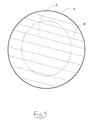
- FIG. 5 Annexed to this description a cross-sectional view of such a support having, radially inward of its outer surface (at the location of which is a surface layer or skin A of the support), this intermediate layer B and said core C.
- the object of the present invention is to provide a method of expanding at least one partially crosslinked blank which is intended to constitute in the crosslinked and expanded state all or part of an elastomeric security support of closed cell cell structure, said or each support being intended to be mounted on a wheel rim inside an envelope of pneumatic, which overcomes the aforementioned drawback in connection with the use a mold for crosslinking.
- an expansion method is such that it consists in cooking said or each blank in a bath of overpressure fluid contained inside an enclosure, the temperature of said bath comprising a maximum value between 110 ° C and 210 ° C, and the absolute pressure of said bath comprising at least a value equal to or greater than 5 bars and a final relaxation value substantially equal to 1 bar, for the expansion of said or each draft in such a way that the increase in volume thereof is unlimited vis-à-vis of said enclosure.
- this expansion method consists in making varying in a discrete or continuous manner said absolute pressure of said fluid between a value maximum less than or equal to 26 bars and a value less than said maximum value.
- this expansion method consists in using a liquid fluid, such as water, or gas, such as hot air, steam or nitrogen, for cooking said or each draft.
- a liquid fluid such as water, or gas, such as hot air, steam or nitrogen, for cooking said or each draft.
- this expansion method consists in cooling said bath to a temperature less than or equal to 100 ° C. and to an absolute pressure between 1 bar and 26 bars, following the cooking of said or each blank.
- this expansion method consists in cooking in said bath several drafts of linear and / or curved shapes.
- supports or parts of supports thus obtained may present variable shapes and dimensions depending on the desired applications.
- the present invention also relates to a crosslinking and expansion process at least one crosslinkable and expandable blank which is intended to constitute in the crosslinked state and expanded all or part of an elastomeric security support of cell-cell structure closed, said support being intended to be mounted on a wheel rim inside a tire casing.
- a crosslinkable blank means a blank which can still be crosslinked, independently of previous heat treatments may have caused the onset of crosslinking. Therefore, for example is considered as crosslinkable, a blank having been subjected beforehand to a heat treatment involving superficial crosslinking. This heat treatment may have consisted of a preheating in an oven of an extruded blank and / or in the very operation of shaping a blank, in the case where it is an injection molding or transfer, for example.
- this crosslinking and expansion method overcomes the toric geometry of the blank which is traditionally imposed by the use of a mold, and that it also makes it possible to obtain supports or parts cross-linked and expanded supports with complex geometries that would be difficult demouldable under satisfactory conditions, such as grooves and / or lobes and / or recesses in any of the directions of the support or of the support part, for example example.
- this crosslinking / expansion operation without a mold for the crosslinking makes it possible to obtain supports or parts of supports which do not have a joint plane, which does not weaken the support or the corresponding support part.
- the crosslinking and expansion method according to the invention consists to use one or more blanks which are each based on an isoprene copolymer and isobutylene (butyl rubber or IIR).
- This elastomer has in particular a reduced air permeability.
- one could also use for the one or more outlines the halogenated versions of this copolymer in particular halogenated or brominated (BIIR or CIIR rubbers, respectively bromobutyl and chlorobutyl rubbers), copolymers of dienes and alpha-olefins, for example terpolymers of ethylene, propylene and a diene (EPDM), polychloroprene (CR), another rubber cutting natural (NR) and polybutadiene (BR) in substantially identical proportions.
- BIIR or CIIR rubbers bromobutyl and chlorobutyl rubbers
- EPDM terpolymers of ethylene, propylene and a diene
- CR polychloroprene
- NR rubber cutting natural
- BR polybutadiene
- compartments make it possible to crosslink and expand units of blanks in continuous mode, including an automated movement of each unit to inside the same compartment and / or from one compartment to another, thanks to the aforementioned openings and movable partitions.
- these partitions and openings allow, when they are in the closed position, to form airlocks at the location of the introduction and extraction compartments and, when said openings are in the closed position and said partitions in the open position, at one or the other of said introduction and extraction compartments (which is then filled with fluid) of alternately form a pressure balance with the adjoining cooking compartment which meanwhile is filled with fluid continuously.
- this crosslinking / expansion device can advantageously be integrated into a global process for manufacturing supports or sections of supports implemented in continuous mode, that is to say directly downstream of the shaping, for example by extrusion or injection, and preheating of the blanks shaped in an oven.
- a cooking device can include any means automated systems suitable for controlling and controlling process parameters expansion / crosslinking such as temperature, pressure and cooking water flow, especially.
- a cooking device for the implementation of said crosslinking and expansion method which is of the type comprising an enclosure which is provided with means for the introduction and extraction of said or each blank, means for receiving said or each blank, means for filling said enclosure with liquid or gaseous fluid, and means for heating and pressurizing the fluid contained inside said pregnant, is such that said enclosure is provided with a plurality of receiving means respectively designed to receive several blanks, said receiving means being mounted adjacent to each other on a pipe intended for filling with fluid of said enclosure and extending to the inside of it.
- said enclosure comprises an outlet pipe connected to means for circulating said fluid in the direction said means for filling the enclosure.
- the sliding means for putting the interior of the pressure vessel may be of the piston type, and that said means of heating may for example include a coil traversed by a heat transfer fluid, or an electrical resistance.
- the fluid which can be used in this embodiment is preferably made up of a liquid, the boiling point of this liquid being above the temperature used for cooking, which can vary from 110 ° C to 210 ° C.
- a safety support section according to the invention, or such support also according to the invention are obtained by the aforementioned crosslinking / expansion method, said section being made of a crosslinked and expanded rubber composition having a structure closed cell cell.
- these cross-linked and expanded sections or supports according to the invention can each comprise, radially inwards of their external surface, a layer intermediate whose thickness is between 5% and 30% of the smallest dimension of a cross section of said section or of said support and whose density is lower than that from the heart of said section or of said support.
- This low density intermediate layer minimizes overheating internal of the rolling support at zero pressure.
- the cross-linked sections or supports and foams obtained each have a maximum density in a surface layer at the location of their external surface, radially outside said layer intermediate.
- this surface layer which has a high density close to that of the corresponding unexpanded blank, gives the support or the support section a surface resistance which is suitable, on the one hand, for direct mounting on the rim and, on the other hand, on repeated contact with the reliefs on the internal face of a tire casing.
- the cross-linked supports or sections and foams obtained each have an average density of between 0.04 and 0.4 and, by example, substantially equal to 0.13.
- An average density close to 0.4 makes it possible to impart high structural rigidity to the corresponding support, which is particularly intended to equip tires bearing heavy loads.
- the respective diameters of said cells vary on average from 0.1 mm to 2 mm, on a cross section of said support or section.
- said crosslinked or said crosslinked and expanded support are each based of a copolymer of isoprene and isobutylene.
- said section or said crosslinked support and expanded each comprises, as reinforcing filler, a cut of 10 to 30 pce of silica and from 10 to 30 pce of carbon black (pce: parts by weight per hundred parts elastomer (s)).
- the silica that can be used can be any reinforcing silica known to those skilled in the art, in particular any precipitated or pyrogenic silica having a BET surface as well as a CTAB specific surface, both less than 450 m 2 / g, even if the precipitated silicas highly dispersible are preferred.
- the BET specific surface is determined in a known manner, according to the Brunauer-Emmet-Teller method described in "The Journal of the American Chemical Society "Vol. 60, page 309, February 1938 and corresponding to standard AFNOR-NFT-45007 (November 1987); the CTAB specific surface is the external surface determined according to the same standard AFNOR-NFT-45007 of November 1987.
- highly dispersible silica any silica having a very important for disagglomeration and dispersion in an elastomeric matrix, observable in known manner by electron or optical microscopy, on fine sections.
- preferred highly dispersible silicas it is possible by example include the Ultrasil VN3 silica from Degussa, as well as the Zeosil 1165 silicas MP and 1115 MP from the company Rhodia.
- silica is also understood to mean mixtures of different silicas, particularly of highly dispersible silicas as described above.
- carbon blacks all carbon blacks are suitable, in particular blacks of the HAF, ISAF, SAF type, conventionally used in tires and particularly in tire treads.
- blacks N115, N134, N234, N339, N347, N375 there may be mentioned blacks N115, N134, N234, N339, N347, N375.
- the mass fraction of carbon black present in the reinforcing filler may vary within large limits, this quantity preferably ranging from 40% to 60%, for a fraction mass of silica ranging from 60% to 40%.
- the support or support section which comprises a base intended to be mounted on said wheel rim and a summit intended to press on the tread of said tire envelope following a fall of pressure inside of it, is such that it has at least one longitudinal groove extending on the said summit substantially at the right of the latter, in the direction of the length of said support or support section.
- the support or support section is such that it has at least one longitudinal recess in its mass, which extends in the direction the length of said support or support section.
- a cooking device comprises an enclosure 1 which is provided with at least one opening 2, 3 for the introduction and extraction of units 4 comprising several blanks 5a, 5b, of means for receiving each blank 5a, 5b, of filling means of said enclosure 1 in liquid or gaseous fluid 6, and of means for heating and placing under pressure of the fluid 6 contained inside said enclosure which are controlled by control means (these means for receiving, filling, heating / placing under pressure and control are not shown for reasons of clarity).
- the crosslinking operation which is carried out in the cooking compartment 8, consists in cooking each unit 4 of crosslinkable and expandable blanks 5a in a bath of fluid 6 in overpressure, so that each blank interacts with said bath 6 independently of compartment 8, the temperature of said bath 6 comprising a value maximum between 110 ° C and 210 ° C and the absolute pressure of said bath 6 comprising at minus a value equal to or greater than 14 bars.
- expansion As for the expansion operation, it is initiated in the cooking compartment 8 during crosslinking (the blowing agent present in each blank 5a decomposes, this which initiates cell germination), but expansion (in the usual sense of increasing volume, which is assigned to this term in the present description) actually takes place only in the extraction compartment 10, when the latter is devoid of the fluid 6 and is located rendered at atmospheric pressure.
- the temperature of said bath 6 in the cooking compartment 8 includes a maximum value between 110 ° C and 210 ° C, and the absolute pressure of said bath 6 includes at least a value equal to or greater than 5 bars.
- each crosslinked blank 5b which occurs at a final relaxation value of the absolute pressure at 1 bar, is achieved in such a way that the increase in volume of each blank 5b is unlimited vis-à-vis the compartment extraction 10, to give the support or part of reticulated and expanded support 5c corresponding.
- This device can operate in continuous mode, advantageously directly downstream blanks processing stations (for example made of extruders) and processing stations preheating of shaped blanks in an oven, reproducing the cycle over time following operations.
- a unit 4 of higher rank is introduced in parallel ( n + 3 in the example of FIG. 1) in the introduction compartment 7, previously open to atmospheric pressure, then the opening 3 of the compartment 10 is then closed to transfer to the compartment 7 the fluid 6 contained in the extraction compartment 10, as indicated by the arrow A in FIG. 1 (the partition 11 of the compartment 10 having been previously actuated in the partitioning position).
- the opening 3 of the compartment 10 is then opened, to allow the blanks 5b of the unit 4 of rank n + 1 to expand, due to the equilibrium at atmospheric pressure, then the blanks are extracted. 5c crosslinked and expanded from this unit.
- FIGs. 2 and 3 Another example of embodiment of a baking according to the invention for the crosslinking / expansion of a unit 4 of blanks 5a.
- This cooking device has an opening 2, for the introduction of a unit 4 crosslinkable and expandable blanks 5a (see Fig. 2) and for extracting the unit 4 corresponding to the cross-linked and expanded supports or parts 5c which are shown in dotted lines in FIG. 3 (at the end of the expansion operation).
- These measures also comprises means for filling the enclosure 1 which consist of a line 13 leading to an opening 14 of said enclosure 1.
- Line 13 is provided with means 15 which slide in a sealed manner on the internal face of its wall for pressurizing the fluid 6 contained inside said enclosure 1 (see arrow C in Fig. 3, in which the opening 2 has been closed for the filling of enclosure 1 with fluid 6).
- This means 15 is for example of the piston type.
- the fluid 6 which can be used in this exemplary embodiment preferably consists of a liquid, the boiling point of this liquid being above the temperature used for crosslinking / expansion, which can vary from 110 ° C to 210 ° C.
- line 13 is also adapted to allow the emptying of said pregnant 1.
- This cooking device also includes heating means 16 for the fluid 6 which are mounted around said enclosure 1 and said pipe 13.
- These heating means 16 may consist of a coil traversed by a heat transfer fluid, or of a electrical resistance.
- the cooking device of Figs. 2 and 3 includes means for reception of the blanks 5a inside the enclosure 1, as well as control means pressure and temperature parameters.
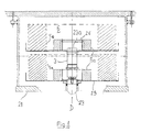
- FIG. 4 Another example of a cooking device according to the invention is shown in FIG. 4.
- This device essentially consists of an enclosure 21 which is provided with a fluid inlet pipe 23 (see arrow D) emerging inside the enclosure 21 by its end 23a, said line 23 being connected to a heating and pressurizing circuit of the bath 6 of fluid contained in the enclosure 21, and of a separate fluid outlet pipe of said inlet pipe 23 (this heating / pressurizing circuit and said pipe are not shown).
- this device also includes means for introducing crosslinkable and expandable blanks 5a inside the enclosure 21, as well as for extracting the corresponding cross-linked and expanded supports or parts 5c.
- the inlet pipe 23 is adapted for support at regular height intervals trays 25 which are each intended to receive a blank 5a, for the crosslinking / expansion thereof.
- each plate 25 could receive blanks 5a having a shape any, for example linear, in order to obtain linear sections of supports in place and place of toric supports.
- Each plate 25 is provided with means 26 for centering the corresponding blank 5a during its installation.
- these means 26 consist of a centering shim around which the blank 5a is intended to be positioned.
- the crosslinking operation consists in baking the crosslinkable and expandable blanks 5a in the fluid bath 6 in overpressure, so that each blank interacts with said bath 6 independently of walls of the enclosure 1, 21. More specifically, the temperature of the bath 6 includes a value maximum between 110 ° C and 210 ° C and its absolute pressure includes at least one value equal to or greater than 14 bars.
- the expansion operation it is initiated in said bath 6 provided that the temperature thereof includes a maximum value between 110 ° C and 210 ° C, and that its absolute pressure comprises at least a value equal to or greater than 5 bars, and the increase in volume of the blank 5a, resulting from the expansion, actually occurs after this is found at atmospheric pressure by opening the enclosure 1, 21 (see the supports 5c dotted in Figs. 3 and 4).
- cooking in the bath 6 can advantageously be implemented with a continuous fluid flow, due to the permanent circulation of the fluid from said outlet pipe to said inlet pipe 23.
- a plurality of tests was carried out, using for the sketches two compositions of crosslinkable and expandable rubber which are both based on butyl rubber but which essentially differ from each other, in the sense that a first composition A includes a reinforcing filler made of carbon black, while a second composition B includes a reinforcing filler consisting of a blend of carbon black and silica.
- Each blank was previously preheated using hot air in an oven electric without pressure, for a period of 70 minutes and at a temperature of 90 ° C.
- the crosslinking / expansion operation was carried out using water as a cooking fluid.
- a device such as that described in connection with FIG. 4, in such a way that the flow of water circulation from said outlet pipe to said inlet pipe 23 be kept at 15 liters of water per minute.
- the drain rate is adjusted in such a way that the passage of said ultimate overpressure value at atmospheric pressure takes place in a sufficiently long time, which in the tests carried out is at least 30 seconds.
- Trial Crosslinkable and expandable composition rough length (mm) first level (bars, min., ° C.) second level (bars, min., ° C) cooling (bars, min., ° C) # 1 AT 412 12 - 90 - 142 - 12-20-20 # 2 AT 355 23 - 90 - 142 - 23 - 20 - 20 # 3 AT 275 23 - 50 - 142 - 23 - 10 - 20 # 4 AT 275 16 - 90 - 142 - 16 - 20 - 20 # 5 AT 275 23 - 60 - 142 9 - 40 - 142 9 - 20 - 20 # 6 AT 275 16 - 90 - 142 9 - 40 - 142 9 - 20 - 20 # 7 AT 275 23 - 60 - 142 12 - 40 - 142 9 - 20 - 20 # 8 B 275 23 - 60 - 142 9 - 40 - 142 9 - 20 - 20 - 20
- Each of these crosslinked and expanded supports is characterized, on the one hand, by a layer intermediate B a few mm thick radially inward of its outer surface and, on the other hand, by a surface layer A at the location of said outer (see Fig. 5).
- the support obtained by test n ° 1 has insufficient crosslinking, due to the insufficient value of the pressure which is used, value not in accordance with the invention (12 bars in relative pressure).
- the support obtained by test n ° 2 which corresponds to the use of a relative pressure 23 bars in the enclosure (maximum value used for all tests), has a cell size according to the invention (because between 0.1 and 2 mm).
- the support obtained by test n ° 3 shows crosslinking and expansion insufficient, due to a too short residence time in the cooking bath, this insufficient expansion resulting from premature halting of the decomposition reaction the blowing agent.
- the support obtained by test n ° 4 (using a single bearing at the relative pressure of 16 bar) has good cross-linking and expansion, as well as a size of cells according to the invention.
- the support obtained by test n ° 5 (using two stages including the pressure values 23 bars and 9 bars respectively) also has cross-linking and satisfactory expansion.
- test n ° 6 (using two stages including the pressure values relative are 16 bars and 9 bars respectively) has increased expansion compared to to that of the previous support (test n ° 5), as shown by the size of the cells which is significantly doubled.
- the support obtained by test n ° 7 (using two stages including the pressure values 23 bars and 12 bars respectively), also has characteristics satisfactory crosslinking and expansion.
- support including a black cut of carbon and silica as reinforcing filler, it also has crosslinking and satisfactory expansion. In addition, this expansion is very high in the core of the support.
- each of the supports obtained by the method according to the invention is characterized by cell diameters relatively close to each other, from the heart to the support area.
- the intermediate layer B of each support according to the invention is of a thickness less than that of the known supports obtained by traditional processes, and that this layer B has an overall density of less than that of the corresponding layer B of such a known support.
- the average cell size on a cross section support is highest when the relative pressures of the first and second bearings are 16 bars and 9 bars respectively (test n ° 6), while on the contrary it is the most reduced in the case of the use of a single level of pressure relative to 23 bars (test n ° 2).
- compositions C and D Details the respective formulations of these compositions C and D. (pce: parts by weight per hundred parts of elastomer). Components introduced into the mixer Composition C (rate in pce) Composition D (rate in pce) Carbon black N683 40 40 "Zeosil 1165 MP" silica - - bulking agent (azobisformamide) 12 11
- Each blank was previously preheated using hot air in an oven ventilated, for a period of 70 minutes and at a temperature of around 100 ° C.
- the crosslinking / expansion operation is as previously carried out by means of of a continuous flow of water, by means of a device such as that of FIG. 4, in such a way as circulation and drainage rates (for crosslinking and expansion, respectively) are kept at 15 liters of water per minute.
- Crosslinked and expanded supports support mass (g) outer perimeter (mm) inside perimeter (mm) width (mm) Volume (liters) Average density # 9 2755 1907 1110 170 26,489 0.104 # 10 2708 - - - - - # 11 2725 2007 1275 178 28,362 0.096 # 12 2752 2018 1300 178 28,212 0.098 # 13 2718 1987 1230 175 28,024 0.097 # 14 2748 1978 1190 163 26,211 0.105 # 15 2738 2002 1295 181 28,212 0.097 # 16 2738 2028 1320 185 29,414 0.093 # 17 2698 2050 1225 177 31,024 0.087 # 18 2724 1975 1236 183 28,885 0.094 n ° 19 2733 2022 1300 180 28,749 0.095 # 20 2738 2060 1345 182 29.602 0.092 n
- the average density of a crosslinked and expanded support according to the invention can vary widely between 0.04 and 0.4, average densities close to 0.04 or 0.4 which can respectively be obtained in a manner known to a person skilled in the art in increasing or reducing the level of blowing agent in the rubber composition corresponding.
- each support according to the invention is characterized by cell diameters very close to each other, from the heart to the surface of the supports.
- the intermediate layer B that each support has according to the invention has a thickness of less than 5 mm, unlike that of traditional supports which are generally between 8 and 25 mm (for width and height supports 200 mm and 120 mm respectively), which minimizes the spread in the core of the support the deformations due to shear stresses and, by Consequently, the internal heating of the latter when running at zero pressure.
Landscapes
- Engineering & Computer Science (AREA)
- Mechanical Engineering (AREA)
- Heating, Cooling, Or Curing Plastics Or The Like In General (AREA)
- Tyre Moulding (AREA)
- Tires In General (AREA)
- Molding Of Porous Articles (AREA)
- Blow-Moulding Or Thermoforming Of Plastics Or The Like (AREA)
Abstract
- la réticulation consiste à cuire l'ébauche expansible ou expansée (5a) dans un bain (6) de fluide en surpression contenu à l'intérieur d'une enceinte (21), de manière que l'ébauche (5a) interagisse avec le bain (6) indépendamment de l'enceinte (21), la température du bain (6) comprenant une valeur maximale comprise entre 110° C et 210° C et la pression absolue dudit bain (6) comprenant au moins une valeur égale ou supérieure à 14 bars, et que
- l'expansion consiste à cuire l'ébauche réticulable ou réticulée (5a, 5b) dans le bain (6), la température du bain (6) comprenant une valeur maximale comprise entre 110° C et 210° C, et la pression absolue du bain (6) comprenant au moins une valeur égale ou supérieure à 5 bars et une valeur finale de détente sensiblement égale à 1 bar, pour l'expansion de l'ébauche (5a, 5b) de manière que son augmentation de volume soit illimitée vis-à-vis de l'enceinte (21).
Description
- ladite réticulation consiste à cuire ladite ou chaque ébauche expansible ou expansée dans un bain de fluide en surpression contenu à l'intérieur d'une enceinte, de telle manière que ladite ou chaque ébauche interagisse avec ledit bain indépendamment de ladite enceinte, la température dudit bain comprenant une valeur maximale comprise entre 110° C et 210° C et la pression absolue dudit bain comprenant au moins une valeur égale ou supérieure à 14 bars , et en ce que
- ladite expansion consiste à soumettre ladite ou chaque ébauche réticulable ou réticulée à un procédé d'expansion selon l'invention tel que défini ci-dessus.
- dans une première étape, à soumettre ladite ou chaque ébauche réticulable et expansible à ladite réticulation pour l'obtention d'une ébauche pratiquement réticulée et expansible, puis
- dans une seconde étape, à soumettre ladite ou chaque ébauche pratiquement réticulée et expansible obtenue suite à ladite première étape à ladite expansion, pour l'obtention de tout ou partie dudit appui de sécurité réticulé et expansé correspondant.
- dans une première étape, à soumettre ladite ou chaque ébauche réticulable et expansible à ladite expansion pour l'obtention d'une ébauche réticulable et pratiquement expansée, puis
- dans une seconde étape, à soumettre ladite ou chaque ébauche réticulable et pratiquement expansée à ladite réticulation pour l'obtention de tout ou partie dudit appui de sécurité réticulé et expansé correspondant.
est tel que ladite enceinte comporte:
- un compartiment d'introduction pourvu à son entrée d'une ouverture pour l'introduction dans ledit compartiment d'une unité d'ébauches réticulables et expansibles en vue de sa cuisson, ladite ouverture d'introduction étant pourvue d'un moyen pour son obturation,
- un compartiment de cuisson prévu en aval dudit compartiment d'introduction et pourvu à son entrée d'une première cloison mobile pour sa mise en communication avec ledit compartiment d'introduction, ledit compartiment de cuisson étant destiné à contenir ledit fluide chauffé et sous pression pour l'obtention d'une unité d'ébauches réticulées et expansibles, et
- un compartiment d'extraction prévu en aval dudit compartiment de cuisson, pourvu à son entrée d'une seconde cloison mobile pour sa mise en communication avec ledit compartiment de cuisson et à sa sortie d'une ouverture à la pression atmosphérique pour l'obtention d'une unité d'ébauches réticulées et expansées et leur extraction de ladite enceinte, ladite ouverture d'extraction étant pourvue d'un moyen pour son obturation,
- des moyens pour transférer en alternance ledit fluide en surpression dudit compartiment d'extraction vers ledit compartiment d'introduction, et dudit compartiment d'introduction vers ledit compartiment d'extraction.
est tel que ladite enceinte est pourvue d'une pluralité de moyens de réception respectivement prévus pour recevoir plusieurs ébauches, lesdits moyens de réception étant montés adjacents les uns aux autres sur une conduite destinée au remplissage en fluide de ladite enceinte et s'étendant à l'intérieur de celle-ci.
- lesdits moyens de remplissage de l'enceinte sont constitués d'une conduite débouchant sur une ouverture de ladite enceinte, ladite conduite étant pourvue d'un moyen coulissant d'une manière étanche sur la face interne de sa paroi pour la mise sous pression du fluide contenu à l'intérieur de ladite enceinte, cette conduite étant également adaptée pour permettre la vidange de ladite enceinte, et que
- lesdits moyens de chauffage dudit fluide sont montés autour de ladite enceinte et de ladite conduite.
- un compartiment d'introduction 7 pourvu à son entrée d'une ouverture 2 pour l'introduction d'une unité 4 d'ébauches 5a réticulables et expansibles, ladite ouverture d'introduction 2 étant pourvue d'un moyen 2a pour permettre sa libération ou son obturation (cette ouverture 2 est représentée en position obturée à la Fig. 1),
- un compartiment de cuisson 8 prévu en aval du précédent et pourvu à son entrée d'une première cloison mobile 9 pour sa mise en communication avec ledit compartiment d'introduction 7 (cette cloison 9 est représentée en position de cloisonnement étanche à la Fig. 1). Ce compartiment de cuisson 8 est destiné à contenir ledit fluide 6 chauffé et sous pression pour l'obtention d'au moins une unité 4 d'ébauches réticulées et expansibles 5b (dans l'exemple simplement illustratif de la Fig. 1, le compartiment 8 est destiné à recevoir deux unités 4),
- un compartiment d'extraction 10 prévu en aval du précédent, qui est destiné à recevoir une unité 4 desdites ébauches réticulées et expansibles 5b. Ce compartiment 10 est pourvu à son entrée d'une seconde cloison mobile 11 pour sa mise en communication avec ledit compartiment de cuisson 8 (cette cloison 11 est également représentée en position de cloisonnement étanche à la Fig. 1), et à sa sortie d'une ouverture 3 pour l'extraction de ladite enceinte 1 d'une unité 4 d'ébauches réticulées et expansées 5c, ladite ouverture d'extraction 3 (représentée en position ouverte à la Fig. 1) étant pourvue d'un moyen 3a pour sa libération ou son obturation, et
- des moyens 12 pour transférer en alternance le fluide 6 en surpression du compartiment d'extraction 10 vers le compartiment d'introduction 7, et vice versa (on a représenté un organe 12a de mise en mouvement du fluide 6 à la Fig. 1, par exemple constitué d'une pompe).
| (pce: parties en poids pour cent parties d'élastomère). | ||
| Constituants introduits dans le mélangeur | Composition A (taux en pce) | Composition B (taux en pce) |
| Noir de carbone N683 | 40 | 20 |
| Silice « Zeosil 1165 MP » | - | 20 |
| agent de gonflement (azobisformamide) | 13 | 13 |
| Essai | Composition réticulable et expansible | longueur ébauche (mm) | premier palier (bars, min.,° C.) | second palier (bars, min.,° C) | refroidissement (bars, min.,° C) |
| n° 1 | A | 412 | 12 - 90 - 142 | - | 12-20-20 |
| n° 2 | A | 355 | 23 - 90 - 142 | - | 23 - 20 - 20 |
| n° 3 | A | 275 | 23 - 50 - 142 | - | 23 - 10 - 20 |
| n° 4 | A | 275 | 16 - 90 - 142 | - | 16 - 20 - 20 |
| n° 5 | A | 275 | 23 - 60 - 142 | 9 - 40 - 142 | 9 - 20 - 20 |
| n° 6 | A | 275 | 16 - 90 - 142 | 9 - 40 - 142 | 9 - 20 - 20 |
| n° 7 | A | 275 | 23 - 60 - 142 | 12 - 40 - 142 | 9 - 20 - 20 |
| n° 8 | B | 275 | 23 - 60 - 142 | 9 - 40 - 142 | 9 - 20 - 20 |
| Appuis réticulés et expansés | largeur (mm) | hauteur (mm) | diamètres maxima des cellules à coeur (mm) | diamètres maxima des cellules à mi-épaisseur (mm) | diamètres maxima des cellules dans la couche B (mm) |
| n° 1 (2 appuis réalisés) | 115 165 | 63 110 | non mesurés | non mesurés | non mesurés |
| n° 2 | 182 | 123,5 | 0,2 | 0,2 | 0,3 - 0,5 |
| n° 3 | 105 | 50 | non mesurés | non mesurés | non mesurés |
| n° 4 | 190 | 130 | 0,3 | 0,3 | 0,5 |
| n° 5 | 193 | 106 | 0,5 | 0,5 | 0,5 |
| n° 6 | 197 | 111 | 1 | 1 | 0,7 |
| n° 7 | 192 | 121 | 0,3 | 0,3 | 0,4 |
| n° 8 | 208 | 118 | 1,8 | 1,3 | 0,7 |
| (pce: parties en poids pour cent parties d'élastomère). | ||
| Constituants introduits dans le mélangeur | Composition C (taux en pce) | Composition D (taux en pce) |
| Noir de carbone N683 | 40 | 40 |
| Silice « Zeosil 1165 MP » | - | - |
| agent de gonflement (azobisformamide) | 12 | 11 |
| Essai | Comp. réticulable et expansible | périmètre ébauche (mm) | masse ébauche (g) | premier palier (bars, min.,° C.) | second palier (bars, min.,° C) | refroidissement (bars, min.,° C) |
| n° 9 | A | 871 | 2785 | 23 - 95 - 142 | 23 - 15 - 20 | |
| n° 10 | A | 868 | 2738 | 23 - 55 - 146 | ||
| n° 11 | A | 859 | 2755 | 23 - 60 - 142 | 12 - 50 - 142 | 12 - 20 - 20 |
| n° 12 | A | 870 | 2782 | 23 - 60 - 142 | 9 - 40 - 142 | 9-20-20 |
| n° 13 | A | 856 | 2748 | 16 - 60 - 142 | 9 - 50 - 142 | 9 - 20 - 20 |
| n° 14 | A | 872 | 2778 | 16 - 60 - 142 | 12 - 40 - 142 | 12 - 20 - 20 |
| n° 15 | A | 867 | 2768 | 23 - 60 - 142 | 9 - 40 - 142 | 9 - 20 - 20 |
| n° 16 | A | 873 | 2768 | 23 - 60 - 142 | 9 - 40 - 142 | 9-20-20 |
| n° 17 | A | 869 | 2728 | 16 - 60 - 142 | 12 - 50 - 142 | |
| n° 18 | A | 856 | 2754 | 23 - 30 - 142 | 12 - 40 - 142 | 12 - 20 - 20 |
| n° 19 | A | 866 | 2763 | 23 - 60 -142 | 9 - 40 - 142 | 9 - 20 - 20 |
| n° 20 | A | 868 | 2768 | 23 - 60 - 142 | 9 - 40 - 142 | 9 - 20 - 20 |
| n° 21 | A | 869 | 2772 | 23 - 60 - 142 | 9 - 40 - 142 | 9 - 20 - 20 |
| n° 22 | A | 867 | 2784 | 23 - 30 - 142 | 12 - 80 - 142 | 12 - 20 - 20 |
| n° 23 | D | 876 | 2765 | 23 - 60 - 142 | 9 - 40 - 142 | 9 - 20 - 20 |
| n° 24 | C | 976 | 1140 | 23 - 30 - 146 | 9 - 30 - 146 | 9 - 10 - 20 |
| n° 25 | C | 982 | 1144 | 23 - 30- 146 | 9 - 40 - 146 | 9 - 20 - 20 |
| n° 26 | B | 814 | 2726 | 23 - 60 - 142 | 9 - 60 - 142 | 9 - 20 - 20 |
| n° 27 | B | 848 | 2746 | 23 - 60 - 142 | 9 - 50 - 142 | 9 - 20 - 20 |
| n° 28 | B | 865 | 2738 | 23 - 60 - 142 | 9 - 60 - 142 | 9 - 20 - 20 |
| Appuis réticulés et expansés | masse appui (g) | périmètre extérieur (mm) | périmètre intérieur (mm) | largeur (mm) | Volume (litres) | Densité moyenne |
| n° 9 | 2755 | 1907 | 1110 | 170 | 26,489 | 0,104 |
| n° 10 | 2708 | - | - | - | - | - |
| n° 11 | 2725 | 2007 | 1275 | 178 | 28,362 | 0,096 |
| n° 12 | 2752 | 2018 | 1300 | 178 | 28,212 | 0,098 |
| n° 13 | 2718 | 1987 | 1230 | 175 | 28,024 | 0,097 |
| n° 14 | 2748 | 1978 | 1190 | 163 | 26,211 | 0,105 |
| n° 15 | 2738 | 2002 | 1295 | 181 | 28,212 | 0,097 |
| n° 16 | 2738 | 2028 | 1320 | 185 | 29,414 | 0,093 |
| n° 17 | 2698 | 2050 | 1225 | 177 | 31,024 | 0,087 |
| n° 18 | 2724 | 1975 | 1236 | 183 | 28,885 | 0,094 |
| n° 19 | 2733 | 2022 | 1300 | 180 | 28,749 | 0,095 |
| n° 20 | 2738 | 2060 | 1345 | 182 | 29,602 | 0,092 |
| n° 21 | 2742 | 2048 | 1330 | 184 | 28,846 | 0,092 |
| n° 22 | 2754 | 1975 | 1203 | 173 | 27,757 | 0,099 |
| n° 23 | 2735 | 1800 | 1200 | 171 | 20,905 | 0,131 |
| n° 24 | 1110 | 2005 | 1455 | 87,5 | 10,085 | 0,110 |
| n° 25 | 1114 | 2033 | 1474 | 89 | 10,574 | 0,105 |
| n° 26 | 2696 | 1850 | 1020 | 170 | 26,034 | 0,104 |
| n° 27 | 2716 | 1900 | 1200 | 173 | 24,964 | 0,109 |
| n° 28 | 2708 | 1942 | 1185 | 160 | 24,500 | 0,111 |
- Selon l'exemple de réalisation de la Fig. 6, l'appui 5c obtenu comporte une base 30
qui est destinée à être montée sur une jante de roue soit directement, soit par l'intermédiaire
d'une armature ou d'un autre agent de liaison, et un sommet 31 qui est destiné à appuyer sur
une bande de roulement d'enveloppe de pneumatique, suite à une chute de pression à
l'intérieur de celle-ci.
Cet appui 5c présente dans cet exemple plusieurs rainures longitudinales 32 s'étendant sur le sommet 31, sensiblement au droit de ce dernier et dans la direction de la longueur de l'appui 5c.
On notera que le procédé selon l'invention permet également d'obtenir des profils d'appuis 5c présentant, en plus desdites seules rainures 32, d'autres rainures longitudinales (non représentées) dans l'une au moins des deux autres directions de l'appui 5c (par exemple des rainures sur la face 33 de l'appui reliant la base 30 et le sommet 31 entre eux). - Selon l'exemple de réalisation de la Fig. 7, l'appui 5c obtenu présente entre sa base 40 et son sommet 41 un évidement longitudinal 42 dans sa masse, qui s'étend dans la direction de sa longueur.
Claims (25)
- Procédé d'expansion d'au moins une ébauche partiellement réticulée (5b) qui est destinée à constituer à l'état réticulé et expansé tout ou partie d'un appui de sécurité élastomère (5c) de structure cellulaire à cellules fermées, ledit appui (5c) étant destiné à être monté sur une jante de roue à l'intérieur d'une enveloppe de pneumatique,
caractérisé en ce qu'il consiste à cuire ladite ou chaque ébauche (5b) dans un bain (6) de fluide en surpression contenu à l'intérieur d'une enceinte (1, 21), la température dudit bain (6) comprenant une valeur maximale comprise entre 110° C et 210° C, et la pression absolue dudit bain (6) comprenant au moins une valeur égale ou supérieure à 5 bars et une valeur finale de détente sensiblement égale à 1 bar, pour l'expansion de ladite ou de chaque ébauche (5b) de telle manière que l'augmentation de volume de celle-ci soit illimitée vis-à-vis de ladite enceinte (1, 21). - Procédé d'expansion selon la revendication 1, caractérisé en ce qu'il consiste à faire varier d'une manière discrète ou continue ladite pression absolue dudit fluide entre une valeur maximale inférieure ou égale à 26 bars et une valeur inférieure à ladite valeur maximale.
- Procédé d'expansion selon la revendication 1 ou 2, caractérisé en ce qu'il consiste à utiliser un fluide liquide pour cuire ladite ou chaque ébauche (5b).
- Procédé d'expansion selon la revendication 1 ou 2, caractérisé en ce qu'il consiste à utiliser un fluide gazeux pour cuire ladite ou chaque ébauche (5b).
- Procédé d'expansion selon une des revendications précédentes, caractérisé en ce qu'il consiste à refroidir ledit bain (6) à une température inférieure ou égale à 100° C et à une pression absolue comprise entre 1 bar et 26 bars, suite à la cuisson de ladite ou de chaque ébauche (5b).
- Procédé d'expansion selon une des revendications précédentes, caractérisé en ce qu'il consiste à cuire dans ledit bain (6) plusieurs ébauches (5b) de formes linéaires et/ou incurvées.
- Procédé de réticulation et d'expansion d'au moins une ébauche réticulable et expansible (5a) qui est destinée à constituer à l'état réticulé et expansé tout ou partie d'un appui de sécurité élastomère (5c) de structure cellulaire à cellules fermées, ledit appui (5c) étant destiné à être monté sur une jante de roue à l'intérieur d'une enveloppe de pneumatique, caractérisé en ce que:ladite réticulation consiste à cuire ladite ou chaque ébauche expansible ou expansée (5a) dans un bain (6) de fluide en surpression contenu à l'intérieur d'une enceinte (1, 21), de telle manière que ladite ou chaque ébauche (5a) interagisse avec ledit bain (6) indépendamment de ladite enceinte (1, 21), la température dudit bain (6) comprenant une valeur maximale comprise entre 110° C et 210° C et la pression absolue dudit bain (6) comprenant au moins une valeur égale ou supérieure à 14 bars, et en ce queladite expansion consiste à soumettre ladite ou chaque ébauche réticulable ou réticulée (5a, 5b) à un procédé d'expansion selon une des revendications 1 à 6.
- Procédé de réticulation et d'expansion selon la revendication 7, caractérisé en ce qu'il consiste:dans une première étape, à soumettre ladite ou chaque ébauche réticulable et expansible (5a) à ladite réticulation pour l'obtention d'une ébauche pratiquement réticulée et expansible (5b), puisdans une seconde étape, à soumettre ladite ou chaque ébauche pratiquement réticulée et expansible (5b) obtenue suite à ladite première étape à ladite expansion, pour l'obtention de tout ou partie dudit appui de sécurité réticulé et expansé (5c) correspondant.
- Procédé de réticulation et d'expansion selon la revendication 7, caractérisé en ce qu'il consiste:dans une première étape, à soumettre ladite ou chaque ébauche réticulable et expansible (5a) à ladite expansion pour l'obtention d'une ébauche réticulable et pratiquement expansée, puisdans une seconde étape, à soumettre ladite ou chaque ébauche réticulable et pratiquement expansée à ladite réticulation pour l'obtention de tout ou partie dudit appui de sécurité réticulé et expansé (5c) correspondant.
- Dispositif de cuisson pour la mise en oeuvre du procédé de réticulation et d'expansion selon une des revendications 7 à 9, du type comprenant une enceinte (1) qui est pourvue d'au moins une ouverture (2, 3) pour l'introduction et l'extraction de ladite ou chaque ébauche (Sa, 5c), de moyens de réception (25) de ladite ou de chaque ébauche (5a), de moyens de remplissage (23) de ladite enceinte (1) en fluide liquide ou gazeux, et de moyens de chauffage (16) et de mise sous pression (15) du fluide contenu à l'intérieur de ladite enceinte (1),
caractérisé en ce que ladite enceinte (1) comporte:un compartiment d'introduction (7) pourvu à son entrée d'une ouverture (2) pour l'introduction dans ledit compartiment (7) d'une unité (4) d'ébauches réticulables et expansibles (5a) en vue de sa cuisson, ladite ouverture d'introduction (2) étant pourvue d'un moyen (2a) pour son obturation,un compartiment de cuisson (8) prévu en aval dudit compartiment d'introduction (7) et pourvu à son entrée d'une première cloison mobile (9) pour sa mise en communication avec ledit compartiment d'introduction (7), ledit compartiment de cuisson (8) étant destiné à contenir ledit fluide chauffé et sous pression pour l'obtention d'une unité (4) d'ébauches réticulées et expansibles (5b), etun compartiment d'extraction (10) prévu en aval dudit compartiment de cuisson (8), pourvu à son entrée d'une seconde cloison mobile (11) pour sa mise en communication avec ledit compartiment de cuisson (8) et à sa sortie d'une ouverture (3) à la pression atmosphérique pour l'extraction de ladite enceinte (1) d'une unité (4) d'ébauches réticulées et expansées (5c), ladite ouverture d'extraction (3) étant pourvue d'un moyen (3a) pour son obturation,des moyens (12) pour transférer en alternance ledit fluide en surpression dudit compartiment d'extraction (10) vers ledit compartiment d'introduction (7), et dudit compartiment d'introduction (7) vers ledit compartiment d'extraction (10). - Dispositif de cuisson pour la mise en oeuvre du procédé de réticulation et d'expansion selon une des revendications 7 à 9, du type comprenant une enceinte (21) qui est pourvue de moyens pour l'introduction et l'extraction de ladite ou chaque ébauche (5a, 5c), d'un moyen de réception (25) de ladite ou de chaque ébauche (5a, 5c), de moyens de remplissage (23) de ladite enceinte (21) en fluide liquide ou gazeux, et de moyens de chauffage et de mise sous pression du fluide contenu à l'intérieur de ladite enceinte (21),
caractérisé en ce que ladite enceinte (21) est pourvue d'une pluralité de moyens de réception (25), montés adjacents les uns aux autres sur une conduite (23) destinée au remplissage en fluide de ladite enceinte (21) et s'étendant à l'intérieur de celle-ci. - Dispositif de cuisson selon la revendication 11, caractérisé en ce que ladite enceinte (21) comporte une conduite de sortie reliée à des moyens de mise en circulation dudit fluide en direction desdits moyens de remplissage (23) de l'enceinte (21).
- Dispositif de cuisson pour la mise en oeuvre du procédé de réticulation et d'expansion selon une des revendications 7 à 9, du type comprenant une enceinte (1) qui est pourvue d'au moins une ouverture (2) pour l'introduction et l'extraction de ladite ou chaque ébauche (5a, 5c), de moyens de réception de ladite ou de chaque ébauche (5a, 5c), de moyens de remplissage (13) de ladite enceinte (1) en fluide liquide ou gazeux, et de moyens de chauffage (16) et de mise sous pression du fluide contenu à l'intérieur de ladite enceinte (1), caractérisé en ce quelesdits moyens de remplissage (13) de l'enceinte (1) sont constitués d'une conduite débouchant sur une ouverture (14) de ladite enceinte (1), ladite conduite (13) étant pourvue d'un moyen (15) coulissant d'une manière étanche sur la face interne de sa paroi pour la mise sous pression du fluide contenu à l'intérieur de ladite enceinte (1), cette conduite (13) étant également adaptée pour permettre la vidange de ladite enceinte (1), eten ce que lesdits moyens de chauffage (16) dudit fluide sont montés autour de ladite enceinte (1) et de ladite conduite (13).
- Appui de sécurité (5c) pour pneumatique ou tronçon dudit appui (5c) obtenu par un procédé selon une des revendications 7 à 9, ledit appui ou ledit tronçon (5c) étant constitué d'une composition de caoutchouc réticulée et expansée présentant une structure cellulaire à cellules fermées, ledit appui (5c) étant destiné à être monté sur une jante de roue à l'intérieur d'une enveloppe de pneumatique, caractérisé en ce qu'il comprend, radialement vers l'intérieur de sa surface externe, une couche intermédiaire (B) dont l'épaisseur est comprise entre 5 % et 30 % de la plus petite dimension d'une section transversale dudit tronçon (5c) et dont la densité est inférieure à celle du coeur (C) dudit tronçon (5c).
- Appui ou tronçon dudit appui (5c) selon la revendication 14, caractérisé en ce qu'il présente une densité maximale en une couche superficielle (A) à l'emplacement de sa surface externe, radialement à l'extérieur de ladite couche intermédiaire (B).
- Appui ou tronçon dudit appui (5c) selon la revendication 14 ou 15, caractérisé en ce qu'il présente une densité moyenne comprise entre 0,04 et 0,4.
- Appui ou tronçon dudit appui (5c) selon la revendication 16, caractérisé en ce qu'il présente une densité moyenne sensiblement égale à 0,13.
- Appui ou tronçon dudit appui (5c) selon une des revendications 14 à 17, caractérisé en ce que les diamètres respectifs desdites cellules varient en moyenne de 0,1 mm à 2 mm, sur une section transversale dudit appui ou tronçon (5c).
- Appui ou tronçon dudit appui (5c) selon une des revendications 14 à 18, caractérisé en ce qu'il consiste à utiliser une ou plusieurs ébauches (5a) qui sont chacune à base d'un copolymère d'isoprène et d'isobutylène.
- Appui ou tronçon dudit appui (5c) selon une des revendications 14 à 19, caractérisé en ce qu'il comprend, à titre de charge renforçante, un coupage de 10 à 30 pce de silice et de 10 à 30 pce de noir de carbone (pce: parties en poids pour cent parties d'élastomère(s)).
- Appui ou tronçon dudit appui (5c) selon une des revendications 14 à 20, comportant une base (30, 40) destinée à être montée sur ladite jante de roue et un sommet (31, 41) destiné à appuyer sur la bande de roulement de ladite enveloppe de pneumatique suite à une chute de pression à l'intérieur de celle-ci, caractérisé en ce qu'il présente au moins une rainure longitudinale (32) s'étendant sur ledit sommet (31) sensiblement au droit de ce dernier, dans la direction de la longueur dudit appui ou tronçon d'appui (5c).
- Appui ou tronçon dudit appui (5c) selon une des revendications 14 à 20, caractérisé en ce qu'il présente au moins un évidement longitudinal (42) dans sa masse, qui s'étend dans la direction de la longueur dudit appui ou tronçon d'appui (5c).
- Appui (5c) selon une des revendications 14 à 22, caractérisé en ce qu'il présente sensiblement une forme de tore.
- Tronçon d'appui (5c) selon une des revendications 14 à 22, caractérisé en ce qu'il présente sensiblement une forme de portion de tore.
- Tronçon d'appui (5c) selon une des revendications 14 à 22, caractérisé en ce qu'il présente sensiblement une forme linéaire.
Applications Claiming Priority (2)
| Application Number | Priority Date | Filing Date | Title |
|---|---|---|---|
| FR0006488 | 2000-05-19 | ||
| FR0006488 | 2000-05-19 |
Publications (2)
| Publication Number | Publication Date |
|---|---|
| EP1155801A1 true EP1155801A1 (fr) | 2001-11-21 |
| EP1155801B1 EP1155801B1 (fr) | 2005-08-24 |
Family
ID=8850457
Family Applications (1)
| Application Number | Title | Priority Date | Filing Date |
|---|---|---|---|
| EP01111030A Expired - Lifetime EP1155801B1 (fr) | 2000-05-19 | 2001-05-08 | Procédé et dispoitif de réticulation/expansion d'une ébauche d'appui de sécurité pour pneumatique et appui obtenu par ce procédé |
Country Status (10)
| Country | Link |
|---|---|
| US (3) | US6716380B2 (fr) |
| EP (1) | EP1155801B1 (fr) |
| JP (1) | JP2002160305A (fr) |
| KR (1) | KR20010106278A (fr) |
| CN (1) | CN100333890C (fr) |
| AT (1) | ATE302676T1 (fr) |
| BR (1) | BR0102031A (fr) |
| CA (1) | CA2348108A1 (fr) |
| DE (1) | DE60112838T2 (fr) |
| RU (1) | RU2261174C2 (fr) |
Cited By (3)
| Publication number | Priority date | Publication date | Assignee | Title |
|---|---|---|---|---|
| FR2874857A1 (fr) * | 2004-09-08 | 2006-03-10 | Michelin Soc Tech | Ensemble monte, chambre a air et procede de fabrication d'une chambre a air |
| US8151845B2 (en) | 2007-04-26 | 2012-04-10 | Michelin Recherche Et Technique S.A. | Tire with reduced rolling noise |
| US8863799B2 (en) | 2007-04-26 | 2014-10-21 | Michelin Recherche Et Technique | Tire with a cellular layer |
Families Citing this family (8)
| Publication number | Priority date | Publication date | Assignee | Title |
|---|---|---|---|---|
| ATE302676T1 (de) * | 2000-05-19 | 2005-09-15 | Michelin Soc Tech | Verfahren und vorrichtung zur vernetzung und schäumen von notlaufstützkörper für fahrzeugreifen und damit hergestellte körper |
| WO2005102742A1 (fr) * | 2004-04-27 | 2005-11-03 | Toyo Tire & Rubber Co., Ltd. | Corps support de pneu à plat, procédé de fabrication dudit element, et pneu à plat sur lequel un corps support de pneu à plat est fixé à demeure |
| FR2893526A1 (fr) * | 2005-11-22 | 2007-05-25 | Michelin Soc Tech | Procede et dispositif d'expansion d'un appui de securite |
| EP1958795A1 (fr) * | 2007-02-13 | 2008-08-20 | Hunneman Import B.V. | Pneu doté d'une enveloppe interne |
| FR2950837B1 (fr) * | 2009-10-06 | 2011-11-11 | Hutchinson | Dispositif anti-crevaison pour ensemble monte non pneumatique de vehicule a deux roues, et cet ensemble monte l'incorporant |
| EP2516144B1 (fr) | 2009-12-21 | 2014-09-10 | Pirelli Tyre S.p.A. | Ensemble pneumatique pour motocyclette tout terrain |
| CN106541527B (zh) * | 2015-09-21 | 2018-11-13 | 风神轮胎股份有限公司 | 全钢工程轮胎变温硫化工艺 |
| CN117067585A (zh) * | 2018-12-20 | 2023-11-17 | 捷普有限公司 | 用于3d打印构建板热膨胀的校平器 |
Citations (3)
| Publication number | Priority date | Publication date | Assignee | Title |
|---|---|---|---|---|
| GB1189505A (en) * | 1966-09-28 | 1970-04-29 | Furukawa Electric Co Ltd | A method of Manufacturing Olefin Polymer Foam |
| EP0594072A1 (fr) * | 1992-10-19 | 1994-04-27 | PIRELLI COORDINAMENTO PNEUMATICI S.p.A. | Procédé de moulage pour la fabrication d'articles toriques à partir d'un matériau élastomère expansé, à cellules fermées, à faible densité et appareil associé |
| DE19640039A1 (de) * | 1996-09-29 | 1998-04-02 | Gefinex Gmbh | Kfz-Rad mit Felge und Notlaufeinrichtung |
Family Cites Families (15)
| Publication number | Priority date | Publication date | Assignee | Title |
|---|---|---|---|---|
| US3812225A (en) * | 1967-01-23 | 1974-05-21 | Furukawa Electric Co Ltd | Method of manufacturing foamed crosslinked polyolefin slabs involving multiple expansion techniques and direct gas pressure |
| GB1320052A (en) | 1970-06-01 | 1973-06-13 | Goodyear Tire & Rubber | Method of curing foam inflated tyres |
| US3872201A (en) | 1970-06-01 | 1975-03-18 | Goodyear Tire & Rubber | Method of curing foam inflated tires |
| JPS5734981B2 (fr) * | 1974-02-18 | 1982-07-26 | ||
| DE2714800A1 (de) * | 1977-04-02 | 1978-10-12 | Basf Ag | Verfahren zur herstellung von vernetzten schaumfaehigen formkoerpern aus olefinpolymerisaten |
| US4179256A (en) * | 1978-03-31 | 1979-12-18 | Furukawa Electric Co., Ltd. | Vulcanization apparatus for a continuous length of article of rubber, plastics or the like material |
| US4210187A (en) * | 1978-06-14 | 1980-07-01 | The Goodyear Tire & Rubber Company | Pneumatic tire having self-sealing feature |
| US4418734A (en) * | 1982-03-19 | 1983-12-06 | The Goodyear Tire & Rubber Company | Safety support system |
| SU1426811A1 (ru) * | 1987-03-03 | 1988-09-30 | Ереванское Отделение Научно-Производственного Объединения Всесоюзного Научно-Исследовательского,Проектно-Конструкторского И Технологического Института Кабельной Промышленности | Устройство дл непрерывной вулканизации длинномерных изделий в жидком теплоносителе |
| RU2015894C1 (ru) * | 1991-05-05 | 1994-07-15 | Краснодарский политехнический институт | Устройство для вулканизации резинотехнических изделий |
| US5776991A (en) * | 1995-03-29 | 1998-07-07 | Bridgestone Corporation | Foamed rubber compositions for pneumatic tires and method of producing the same |
| EP0921921B2 (fr) * | 1995-09-20 | 2007-04-04 | Uponor Wirsbo AB | Procede de chauffage et/ou de reticulation de polymeres et dispositif associe |
| EP0937586A1 (fr) * | 1998-02-24 | 1999-08-25 | Marco Märk | Roue pour véhicule |
| ATE302676T1 (de) * | 2000-05-19 | 2005-09-15 | Michelin Soc Tech | Verfahren und vorrichtung zur vernetzung und schäumen von notlaufstützkörper für fahrzeugreifen und damit hergestellte körper |
| BR0114126A (pt) * | 2000-09-11 | 2003-08-26 | Dow Global Technologies Inc | Reforço de pneu para rodar vazio e método de fabricação |
-
2001
- 2001-05-08 AT AT01111030T patent/ATE302676T1/de not_active IP Right Cessation
- 2001-05-08 DE DE60112838T patent/DE60112838T2/de not_active Expired - Fee Related
- 2001-05-08 EP EP01111030A patent/EP1155801B1/fr not_active Expired - Lifetime
- 2001-05-17 BR BR0102031-5A patent/BR0102031A/pt not_active Application Discontinuation
- 2001-05-17 CA CA002348108A patent/CA2348108A1/fr not_active Abandoned
- 2001-05-17 US US09/860,075 patent/US6716380B2/en not_active Expired - Fee Related
- 2001-05-18 JP JP2001188862A patent/JP2002160305A/ja not_active Abandoned
- 2001-05-18 RU RU2001113683/12A patent/RU2261174C2/ru not_active IP Right Cessation
- 2001-05-19 KR KR1020010027468A patent/KR20010106278A/ko not_active Ceased
- 2001-05-21 CN CNB011161647A patent/CN100333890C/zh not_active Expired - Fee Related
-
2004
- 2004-03-02 US US10/791,580 patent/US20040166315A1/en not_active Abandoned
-
2006
- 2006-03-14 US US11/374,092 patent/US20060151083A1/en not_active Abandoned
Patent Citations (3)
| Publication number | Priority date | Publication date | Assignee | Title |
|---|---|---|---|---|
| GB1189505A (en) * | 1966-09-28 | 1970-04-29 | Furukawa Electric Co Ltd | A method of Manufacturing Olefin Polymer Foam |
| EP0594072A1 (fr) * | 1992-10-19 | 1994-04-27 | PIRELLI COORDINAMENTO PNEUMATICI S.p.A. | Procédé de moulage pour la fabrication d'articles toriques à partir d'un matériau élastomère expansé, à cellules fermées, à faible densité et appareil associé |
| DE19640039A1 (de) * | 1996-09-29 | 1998-04-02 | Gefinex Gmbh | Kfz-Rad mit Felge und Notlaufeinrichtung |
Cited By (4)
| Publication number | Priority date | Publication date | Assignee | Title |
|---|---|---|---|---|
| FR2874857A1 (fr) * | 2004-09-08 | 2006-03-10 | Michelin Soc Tech | Ensemble monte, chambre a air et procede de fabrication d'une chambre a air |
| WO2006029958A1 (fr) * | 2004-09-08 | 2006-03-23 | Societe De Technologie Michelin | Ensemble monte, chambre a air et procede de fabrication d'une chambre a air |
| US8151845B2 (en) | 2007-04-26 | 2012-04-10 | Michelin Recherche Et Technique S.A. | Tire with reduced rolling noise |
| US8863799B2 (en) | 2007-04-26 | 2014-10-21 | Michelin Recherche Et Technique | Tire with a cellular layer |
Also Published As
| Publication number | Publication date |
|---|---|
| US20040166315A1 (en) | 2004-08-26 |
| DE60112838T2 (de) | 2006-06-01 |
| US20060151083A1 (en) | 2006-07-13 |
| CN1324717A (zh) | 2001-12-05 |
| US6716380B2 (en) | 2004-04-06 |
| RU2261174C2 (ru) | 2005-09-27 |
| DE60112838D1 (de) | 2005-09-29 |
| CA2348108A1 (fr) | 2001-11-19 |
| CN100333890C (zh) | 2007-08-29 |
| ATE302676T1 (de) | 2005-09-15 |
| KR20010106278A (ko) | 2001-11-29 |
| JP2002160305A (ja) | 2002-06-04 |
| EP1155801B1 (fr) | 2005-08-24 |
| US20020026973A1 (en) | 2002-03-07 |
| BR0102031A (pt) | 2001-12-18 |
Similar Documents
| Publication | Publication Date | Title |
|---|---|---|
| EP1155801B1 (fr) | Procédé et dispoitif de réticulation/expansion d'une ébauche d'appui de sécurité pour pneumatique et appui obtenu par ce procédé | |
| CN1715041B (zh) | 非充气轮胎及其制造方法 | |
| EP0127546B1 (fr) | Procédé et dispositif de fabrication de vitrages surmoulés et produits obtenus | |
| JP2518481B2 (ja) | 自己スキン層付きポリウレタンフォ―ムの製造方法及び製造装置 | |
| JP2008285156A (ja) | 転動時騒音減少型タイヤ | |
| CN100475561C (zh) | 具有拱形胎肩的弹性体轮胎 | |
| US4130619A (en) | Apparatus and method of making hollow articles | |
| CA2696510A1 (fr) | Systeme de presse | |
| US8151840B2 (en) | Method of manufacturing a new airless or pneumatic tire having a reinforced rubber structure and a polyurethane tread | |
| WO2008138081A1 (fr) | Processus de vulcanisation d'artéfacts en caoutchouc comprenant l'application d'un profilé prémoulé dans un autoclave avec l'utilisation de micro-ondes | |
| EP0027417B1 (fr) | Procédé et dispositif de fabrication de chambres du type increvable pour roues de véhicules | |
| FR2478526A1 (fr) | Procede et dispositif pour la fabrication de pneumatiques pour automobiles | |
| RU2001113683A (ru) | Способ структурирования/расширения заготовки предохранительной опоры для пневматической шины и устройство для его осуществления (варианты), предохранительная опора | |
| EP1149678B1 (fr) | Procédé de fabrication d'un appui de sécurité pour pneumatique et appui obtenu par ce procédé | |
| JP2000296523A (ja) | 車の車輪用タイヤの成形・硬化方法及びその装置 | |
| EP3651976B1 (fr) | Procédé de fabrication à plat d'un bandage pneumatique | |
| JPH09123175A (ja) | タイヤまたは空気ばねの加硫のためのゴム製加熱ブラッダー | |
| FR2755400A1 (fr) | Chambre a air ayant une resistance aux crevaisons renforcee et son procede de fabrication | |
| EP1595673B1 (fr) | Procédé d'obtention d'une bande de roulement pour pneumatique | |
| WO1997049566A1 (fr) | Structure gonflable pour pneumatique | |
| EP1514674B1 (fr) | Méthode de fabrication d'un noyau pour le moulage d'un pneumatique, pneumatique et dispositif de fabrication d'un pneumatique correspondants | |
| US1513102A (en) | Method op molding and vulcanizing pneumatic-tire casings | |
| JPH10329232A (ja) | タイヤの製造方法 | |
| WO2018010672A1 (fr) | Nouvel ensemble roue anti-explosion, anti-crevaison sans gonflage et son procédé de fabrication | |
| US1566665A (en) | Method oe producing rubber articles |
Legal Events
| Date | Code | Title | Description |
|---|---|---|---|
| PUAI | Public reference made under article 153(3) epc to a published international application that has entered the european phase |
Free format text: ORIGINAL CODE: 0009012 |
|
| AK | Designated contracting states |
Kind code of ref document: A1 Designated state(s): AT BE CH CY DE DK ES FI FR GB GR IE IT LI LU MC NL PT SE TR |
|
| AX | Request for extension of the european patent |
Free format text: AL;LT;LV;MK;RO;SI |
|
| 17P | Request for examination filed |
Effective date: 20020521 |
|
| AKX | Designation fees paid |
Free format text: AT BE CH CY DE DK ES FI FR GB GR IE IT LI LU MC NL PT SE TR |
|
| GRAP | Despatch of communication of intention to grant a patent |
Free format text: ORIGINAL CODE: EPIDOSNIGR1 |
|
| RIN1 | Information on inventor provided before grant (corrected) |
Inventor name: MENARD, GILBERT Inventor name: DURIF, PIERRE Inventor name: MOREL, NOEL Inventor name: PEYRON, GEORGES |
|
| RIN1 | Information on inventor provided before grant (corrected) |
Inventor name: DURIF, PIERRE Inventor name: MOREL, NOEL Inventor name: MENARD, GILBERT Inventor name: PEYRON, GEORGES |
|
| GRAS | Grant fee paid |
Free format text: ORIGINAL CODE: EPIDOSNIGR3 |
|
| GRAA | (expected) grant |
Free format text: ORIGINAL CODE: 0009210 |
|
| AK | Designated contracting states |
Kind code of ref document: B1 Designated state(s): AT BE CH CY DE DK ES FI FR GB GR IE IT LI LU MC NL PT SE TR |
|
| PG25 | Lapsed in a contracting state [announced via postgrant information from national office to epo] |
Ref country code: FI Free format text: LAPSE BECAUSE OF FAILURE TO SUBMIT A TRANSLATION OF THE DESCRIPTION OR TO PAY THE FEE WITHIN THE PRESCRIBED TIME-LIMIT Effective date: 20050824 Ref country code: AT Free format text: LAPSE BECAUSE OF FAILURE TO SUBMIT A TRANSLATION OF THE DESCRIPTION OR TO PAY THE FEE WITHIN THE PRESCRIBED TIME-LIMIT Effective date: 20050824 Ref country code: IE Free format text: LAPSE BECAUSE OF FAILURE TO SUBMIT A TRANSLATION OF THE DESCRIPTION OR TO PAY THE FEE WITHIN THE PRESCRIBED TIME-LIMIT Effective date: 20050824 Ref country code: NL Free format text: LAPSE BECAUSE OF FAILURE TO SUBMIT A TRANSLATION OF THE DESCRIPTION OR TO PAY THE FEE WITHIN THE PRESCRIBED TIME-LIMIT Effective date: 20050824 |
|
| REG | Reference to a national code |
Ref country code: GB Ref legal event code: FG4D Free format text: NOT ENGLISH |
|
| REG | Reference to a national code |
Ref country code: CH Ref legal event code: EP |
|
| REG | Reference to a national code |
Ref country code: IE Ref legal event code: FG4D Free format text: LANGUAGE OF EP DOCUMENT: FRENCH |
|
| REF | Corresponds to: |
Ref document number: 60112838 Country of ref document: DE Date of ref document: 20050929 Kind code of ref document: P |
|
| PG25 | Lapsed in a contracting state [announced via postgrant information from national office to epo] |
Ref country code: DK Free format text: LAPSE BECAUSE OF FAILURE TO SUBMIT A TRANSLATION OF THE DESCRIPTION OR TO PAY THE FEE WITHIN THE PRESCRIBED TIME-LIMIT Effective date: 20051124 Ref country code: GR Free format text: LAPSE BECAUSE OF FAILURE TO SUBMIT A TRANSLATION OF THE DESCRIPTION OR TO PAY THE FEE WITHIN THE PRESCRIBED TIME-LIMIT Effective date: 20051124 Ref country code: SE Free format text: LAPSE BECAUSE OF FAILURE TO SUBMIT A TRANSLATION OF THE DESCRIPTION OR TO PAY THE FEE WITHIN THE PRESCRIBED TIME-LIMIT Effective date: 20051124 |
|
| PG25 | Lapsed in a contracting state [announced via postgrant information from national office to epo] |
Ref country code: ES Free format text: LAPSE BECAUSE OF FAILURE TO SUBMIT A TRANSLATION OF THE DESCRIPTION OR TO PAY THE FEE WITHIN THE PRESCRIBED TIME-LIMIT Effective date: 20051205 |
|
| GBT | Gb: translation of ep patent filed (gb section 77(6)(a)/1977) |
Effective date: 20051128 |
|
| PG25 | Lapsed in a contracting state [announced via postgrant information from national office to epo] |
Ref country code: PT Free format text: LAPSE BECAUSE OF FAILURE TO SUBMIT A TRANSLATION OF THE DESCRIPTION OR TO PAY THE FEE WITHIN THE PRESCRIBED TIME-LIMIT Effective date: 20060124 |
|
| NLV1 | Nl: lapsed or annulled due to failure to fulfill the requirements of art. 29p and 29m of the patents act | ||
| REG | Reference to a national code |
Ref country code: IE Ref legal event code: FD4D |
|
| PG25 | Lapsed in a contracting state [announced via postgrant information from national office to epo] |
Ref country code: BE Free format text: LAPSE BECAUSE OF NON-PAYMENT OF DUE FEES Effective date: 20060531 Ref country code: MC Free format text: LAPSE BECAUSE OF NON-PAYMENT OF DUE FEES Effective date: 20060531 Ref country code: CH Free format text: LAPSE BECAUSE OF NON-PAYMENT OF DUE FEES Effective date: 20060531 Ref country code: LI Free format text: LAPSE BECAUSE OF NON-PAYMENT OF DUE FEES Effective date: 20060531 |
|
| PLBE | No opposition filed within time limit |
Free format text: ORIGINAL CODE: 0009261 |
|
| STAA | Information on the status of an ep patent application or granted ep patent |
Free format text: STATUS: NO OPPOSITION FILED WITHIN TIME LIMIT |
|
| 26N | No opposition filed |
Effective date: 20060526 |
|
| REG | Reference to a national code |
Ref country code: CH Ref legal event code: PL |
|
| BERE | Be: lapsed |
Owner name: SOC. DE TECHNOLOGIE MICHELIN Effective date: 20060531 Owner name: MICHELIN RECHERCHE ET TECHNIQUE S.A. Effective date: 20060531 |
|
| PG25 | Lapsed in a contracting state [announced via postgrant information from national office to epo] |
Ref country code: TR Free format text: LAPSE BECAUSE OF FAILURE TO SUBMIT A TRANSLATION OF THE DESCRIPTION OR TO PAY THE FEE WITHIN THE PRESCRIBED TIME-LIMIT Effective date: 20050824 Ref country code: LU Free format text: LAPSE BECAUSE OF NON-PAYMENT OF DUE FEES Effective date: 20060508 |
|
| PGFP | Annual fee paid to national office [announced via postgrant information from national office to epo] |
Ref country code: DE Payment date: 20080523 Year of fee payment: 8 |
|
| PGFP | Annual fee paid to national office [announced via postgrant information from national office to epo] |
Ref country code: IT Payment date: 20080523 Year of fee payment: 8 |
|
| PG25 | Lapsed in a contracting state [announced via postgrant information from national office to epo] |
Ref country code: CY Free format text: LAPSE BECAUSE OF FAILURE TO SUBMIT A TRANSLATION OF THE DESCRIPTION OR TO PAY THE FEE WITHIN THE PRESCRIBED TIME-LIMIT Effective date: 20050824 |
|
| PGFP | Annual fee paid to national office [announced via postgrant information from national office to epo] |
Ref country code: GB Payment date: 20080522 Year of fee payment: 8 |
|
| GBPC | Gb: european patent ceased through non-payment of renewal fee |
Effective date: 20090508 |
|
| REG | Reference to a national code |
Ref country code: FR Ref legal event code: ST Effective date: 20100129 |
|
| PG25 | Lapsed in a contracting state [announced via postgrant information from national office to epo] |
Ref country code: FR Free format text: LAPSE BECAUSE OF NON-PAYMENT OF DUE FEES Effective date: 20090602 |
|
| PGFP | Annual fee paid to national office [announced via postgrant information from national office to epo] |
Ref country code: FR Payment date: 20080526 Year of fee payment: 8 |
|
| PG25 | Lapsed in a contracting state [announced via postgrant information from national office to epo] |
Ref country code: GB Free format text: LAPSE BECAUSE OF NON-PAYMENT OF DUE FEES Effective date: 20090508 |
|
| PG25 | Lapsed in a contracting state [announced via postgrant information from national office to epo] |
Ref country code: DE Free format text: LAPSE BECAUSE OF NON-PAYMENT OF DUE FEES Effective date: 20091201 |
|
| PG25 | Lapsed in a contracting state [announced via postgrant information from national office to epo] |
Ref country code: IT Free format text: LAPSE BECAUSE OF NON-PAYMENT OF DUE FEES Effective date: 20090508 |