EP1154556A2 - Schaltungsanordnung zum Betrieb eines Motors - Google Patents
Schaltungsanordnung zum Betrieb eines Motors Download PDFInfo
- Publication number
- EP1154556A2 EP1154556A2 EP01110415A EP01110415A EP1154556A2 EP 1154556 A2 EP1154556 A2 EP 1154556A2 EP 01110415 A EP01110415 A EP 01110415A EP 01110415 A EP01110415 A EP 01110415A EP 1154556 A2 EP1154556 A2 EP 1154556A2
- Authority
- EP
- European Patent Office
- Prior art keywords
- motor
- circuit arrangement
- arrangement according
- control device
- switching element
- Prior art date
- Legal status (The legal status is an assumption and is not a legal conclusion. Google has not performed a legal analysis and makes no representation as to the accuracy of the status listed.)
- Granted
Links
Images
Classifications
-
- H—ELECTRICITY
- H02—GENERATION; CONVERSION OR DISTRIBUTION OF ELECTRIC POWER
- H02P—CONTROL OR REGULATION OF ELECTRIC MOTORS, ELECTRIC GENERATORS OR DYNAMO-ELECTRIC CONVERTERS; CONTROLLING TRANSFORMERS, REACTORS OR CHOKE COILS
- H02P7/00—Arrangements for regulating or controlling the speed or torque of electric DC motors
- H02P7/03—Arrangements for regulating or controlling the speed or torque of electric DC motors for controlling the direction of rotation of DC motors
- H02P7/04—Arrangements for regulating or controlling the speed or torque of electric DC motors for controlling the direction of rotation of DC motors by means of a H-bridge circuit
Definitions
- the invention relates to a circuit arrangement for operating a motor according to the preamble of claim 1.
- haptic feedback can be achieved through such torque transmission for an operator of a rotary knob which is coupled to the motor, produce.
- the forces for the haptic feedback are here by means of a permanently excited DC motor generated, the torque generated is directly proportional to the current flowing through the armature.
- the aforementioned embodiment is achieved by operating as a constant current source the greatest possible independence of the generated torque from Fluctuations in the supply voltage and temperature drifts of the motor.
- this embodiment is mainly used in mains-operated Devices in which the annoying 50 or 100 Hz hum of the power supply unit from the haptic Feedback must be coupled. Human beings are able to Perceive vibrations up to about 500 Hz with his fingertips.
- the above-mentioned first embodiment of the constant current source has the Disadvantage that the control of the bridge creates a power loss.
- fluctuations in the supply voltage in the vehicle area of the order of magnitude between 9 and 16 V would be appropriate dimensioning for a motor that delivers its maximum torque at around 2 A, a power loss of about 14 watts.
- Such a power loss can only be removed in the vehicle area with very complex heat sinks.
- the heat dissipation is cost-intensive and the loss of power loss unfriendly. For the rest, the one generated by the power loss Perceived warmth as irritating. In the case of mains-operated devices, however, this is Power dissipation less disturbing, since the supply voltage is far less there fluctuates greatly.
- the object of the invention is to provide a circuit arrangement for operating a motor, Specify in particular a permanently excited DC motor in which a minimum even with relatively large fluctuations in the supply voltage Power loss while ensuring the generation of a desired torque can be guaranteed.
- a control device which has an input to which the supply voltage U B of the motor or a signal describing this supply voltage U B is present. Furthermore, the control device is designed such that the application of the at least one switching element can be corrected as a function of the supply voltage U B. By controlling the switching element acting on the motor as a function of the supply voltage, torque fluctuations occurring in the motor due to supply voltage fluctuations can be compensated for.
- pulse width modulation control can be used depending on the supply voltage due to a motor characteristic which the extent of a necessary readjustment depending on the supply voltage fluctuation indicates, is adjusted.
- the present invention can be largely independent of the torque from the supply voltage without reaching it excessive power dissipation.
- transistors as switching elements are used, they are only switched on or off and not in linear mode used. The power loss can thus be kept low.
- switching elements Switch used and controlled accordingly.
- a frequency of preferably above 20 kHz When using pulse width modulation as control, a frequency of preferably above 20 kHz.
- a motor When a motor is moved, it generates depending on the speed of rotation a current or an induced voltage. This is either supportive or against an external engine influence. To eliminate this effect, a detected rotational speed of a motor is used to measure the torque regardless of the speed of rotation. This is with one preferred embodiment in the control device an additional input provided, to which a signal is present, which indicates the rotational speed of the motor describes. The control device is then designed such that the application of the at least one switching element as a function of the rotational speed is correctable.
- control device another input to which a temperature signal is present.
- the control device is then designed such that the at least one Switching element also depending on the ambient temperature acting on the motor is correctable.
- the temperature dependency of the motor which is primarily due to the known temperature dependence of the Copper windings is to be compensated.
- the temperature in a vehicle is usually known from the air conditioning system and can Transfer bus systems to the control of the control element and there in the control unit be taken into account.
- an additional one must be taken into account Input provided at the control device, through which a the average current in a signal describing a certain time window is supplied.
- the control device is then designed such that the at least one Switching element can also be corrected as a function of this average current.
- a particularly simple embodiment is characterized in that Switching element four transistors are provided, which in the manner of an H-bridge are connected to the engine. According to a particular embodiment, everyone Transistor a diode connected in parallel as a freewheeling diode.
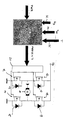
- the drawing shows a schematic representation of a switching arrangement according to the invention, in which a permanently excited DC motor 10 is connected to a voltage supply U B via an H-bridge.
- a permanently excited DC motor 10 is connected to a voltage supply U B via an H-bridge.
- One end of an armature coil of the motor 10 is connected to ground via a transistor 12 and to the supply voltage U B via a transistor 16.
- the other end of the armature coil is in turn connected to ground via a transistor 14 and in turn to the supply voltage U B via a transistor 18. All transistors have freewheeling diodes 13, 15, 17 and 19 connected in parallel.
- the transistors 12, 14, 16 and 18 are controlled by a logic 20 which receives pulse-width-modulated signals PWM (U, v, T) corrected by a control device 30 and converts them into transistor switching signals.
- PWM pulse-width-modulated signals
- control device 30 itself already receives PWM signals, which one defined defined haptic feedback between 0 and 100% of the motor 10 and change these pulse width modulated signals due to the at the Inputs 32, 34 and 36 signals present.
- a supply voltage signal is present at input 32, which represents the supply voltage U B present at motor 10.
- a signal is present at input 34 which describes the adjustment speed of the motor v Mot and is supplied by a microprocessor.
- a temperature signal T is present at input 36, which represents the temperature in the vicinity of motor 10.
- the circuit arrangement is installed in a vehicle in which the supply voltage U B is between 9 and 16 volts.
- the control device 30 is designed such that the pulse width modulation signal entering the control device 30 is changed as a function of the supply voltage U B, the adjustment speed of the motor v Mot and the temperature such that a constant torque is present on the motor 10 even under changing conditions.
- a motor characteristic of the motor 10 which includes readjustments as a function of supply fluctuation values, is stored in the control device 30. Based on this data, the pulse width modulation control is changed as a function of the supply voltage U B.
- the effects of the rotational speed of the motor 10 v Mot and the temperature at the motor 10 are taken into account in the control device 30. This can also be done using characteristic curves which contain the extent to which the pulse width modulation must be changed so that the effects caused by the induced voltage or the temperature effects are compensated for.
- control device issues a corrected pulse width modulation signal PWM (U, vT) to the logic 20, so that the motor is independent of voltage and temperature and can be operated independently of the rotational speed.
- PWM pulse width modulation signal
- a further development not shown in the exemplary embodiment would be included find, although the heating of the armature coil due to the flowing through it Current is taken into account when controlling the motor.
- the middle motor 10 can either externally or in the control device 30 flowing current can be determined in a certain time window. About this medium current can affect the coil heating and thus the necessary Correction in pulse width modulation can be closed.
- the control device 30 would still have to implement a corresponding input have and be designed for appropriate processing.
- the proposed solution generates minimal power loss and is special a suitable solution for the task in the automotive sector.
- This solution can also be used with standard semiconductor bridges common on the market with integrated overtemperature protection.
- the circuit comes from there without additional components, since the supply voltage is already for others Purposes such as B. is detected for diagnosis in the motor vehicle. Furthermore no disadvantages with regard to stability are to be expected, since this is a Control acts. In contrast, quick regulations in the automotive sector would be due the wide range of requirements regarding their faults is difficult to control.
Landscapes
- Engineering & Computer Science (AREA)
- Power Engineering (AREA)
- Control Of Direct Current Motors (AREA)
Abstract
Description
Claims (10)
- Schaltungsanordnung zum Betrieb eines Motors, bei welcher der Motor (10) über zumindest ein Schaltelement (12, 14, 16, 18) mit einer Gleichstrom-Spannungsversorgung UB verbunden und eine Steuereinrichtung (30) vorgesehen ist, die das zumindest eine Schaltelement (12, 14, 16, 18) in vorgegebener Weise derart beaufschlagt, dass der Motor (10) ein definiertes Drehmoment erzeugt,
dadurch gekennzeichnet, dass die Steuereinrichtung (30) einen Eingang (32) aufweist, an dem die Versorgungsspannung UB des Motors (10) oder ein diese Versorgungsspannung UB beschreibendes Signal anliegt und derart ausgebildet ist, dass die Beaufschlagung des zumindest einen Schaltelements (12, 14, 16, 18) in Abhängigkeit von der Versorgungsspannung UB korrigierbar ist. - Schaltungsanordnung nach Anspruch 1,
dadurch gekennzeichnet, dass eine auf den Motor (10) abgestimmte und von der Versorgungsspannung UB abhängige Kennlinie vorgesehen ist und ein Signal für das zumindest eine Schaltelement (12, 14, 16, 18) anhand einer Kennlinie des Motors (10) nachgesteuert wird. - Schaltungsanordnung nach Anspruch 1 oder 2,
dadurch gekennzeichnet, dass die Steuereinrichtung (30) zusätzlich einen Eingang (34) aufweist, an dem ein Signal anliegt, welches die Drehgeschwindigkeit des Motors (10) beschreibt und derart ausgebildet ist, dass die Beaufschlagung des zumindest einen Schaltelements (12, 14, 16, 18) in Abhängigkeit von der Drehgeschwindigkeit korrigierbar ist. - Schaltungsanordnung nach einem der Ansprüche 1 bis 3,
dadurch gekennzeichnet, dass die Steuereinrichtung (30) zusätzlich einen Eingang (36) aufweist, an dem ein Temperatursignal (T) anliegt und derart ausgebildet ist, dass die Beaufschlagung des zumindest einen Schaltelements (12, 14, 16, 18) in Abhängigkeit von der Temperatur (T) korrigierbar ist. - Schaltungsanordnung nach einem der Ansprüche 1 bis 4,
dadurch gekennzeichnet, dass eine Einrichtung zur Ermittlung eines mittleren Stromes durch den Motor (10) innerhalb eines bestimmten Zeitfensters vorgesehen ist und eine Korrektur für die Beaufschlagung des zumindest einen Schaltelements (12, 14,1 6, 18) aufgrund diesen mittleren Stromes vorgenommen wird. - Schaltungsanordnung nach einem der vorhergehenden Ansprüche,
dadurch gekennzeichnet, dass als Schaltelemente vier Transistoren (12, 14, 16, 18) vorgesehen sind, die nach Art einer H-Brücke mit dem Motor (10) verschalten sind. - Schaltungsanordnung nach Anspruch 6,
dadurch gekennzeichnet, dass jedem Transistor (12, 14, 16, 18) eine Diode (13, 15, 17, 19) als Freilauf-Diode parallelgeschaltet ist. - Schaltungsanordnung nach einem der vorhergehenden Ansprüche,
dadurch gekennzeichnet, dass die Steuereinrichtung (30) zur Ansteuerung der Schaltelemente (12, 14, 16, 18) mittels einer Pulsweitenmodulation ausgebildet ist (PWM-Ansteuerung). - Schaltungsanordnung nach Anspruch 8,
dadurch gekennzeichnet, dass die Frequenz der Ansteuerung über 15 kHz liegt. - Schaltungsanordnung nach einem der vorhergehenden Ansprüche,
dadurch gekennzeichnet, dass als Motor ein permanenterregter Gleichstrommotor (10) verwendet ist.
Applications Claiming Priority (2)
| Application Number | Priority Date | Filing Date | Title |
|---|---|---|---|
| DE10022924 | 2000-05-11 | ||
| DE10022924A DE10022924A1 (de) | 2000-05-11 | 2000-05-11 | Schaltungsanordnung zum Betrieb eines Motors |
Publications (3)
| Publication Number | Publication Date |
|---|---|
| EP1154556A2 true EP1154556A2 (de) | 2001-11-14 |
| EP1154556A3 EP1154556A3 (de) | 2003-01-29 |
| EP1154556B1 EP1154556B1 (de) | 2013-09-18 |
Family
ID=7641547
Family Applications (1)
| Application Number | Title | Priority Date | Filing Date |
|---|---|---|---|
| EP01110415.5A Expired - Lifetime EP1154556B1 (de) | 2000-05-11 | 2001-04-27 | Schaltungsanordnung zum Betrieb eines Motors |
Country Status (3)
| Country | Link |
|---|---|
| EP (1) | EP1154556B1 (de) |
| DE (1) | DE10022924A1 (de) |
| ES (1) | ES2430316T3 (de) |
Cited By (2)
| Publication number | Priority date | Publication date | Assignee | Title |
|---|---|---|---|---|
| JP2020137410A (ja) * | 2019-02-18 | 2020-08-31 | バイエル・ウント・ケッペル・ゲーエムベーハー・ウント・コー・カーゲー | Dcポンプモータの制御方法および制御ユニット |
| DE102005020377B4 (de) | 2005-05-02 | 2021-08-12 | Robert Bosch Gmbh | Verfahren zum Betreiben einer Elektrowerkzeugmaschine |
Families Citing this family (2)
| Publication number | Priority date | Publication date | Assignee | Title |
|---|---|---|---|---|
| DE102010048747A1 (de) * | 2010-10-16 | 2012-04-19 | Audi Ag | Vorrichtung zur Steuerung, insbesondere Konstanthaltung, der Drehzahl eines elektrisch betriebenen Gleichstrommotors |
| DE102024112509A1 (de) * | 2024-05-03 | 2025-11-06 | Brose Schließsysteme GmbH & Co. Kommanditgesellschaft | Steueranordnung zum Betrieb eines Kraftfahrzeugschließsystems |
Family Cites Families (9)
| Publication number | Priority date | Publication date | Assignee | Title |
|---|---|---|---|---|
| DE3519840A1 (de) * | 1985-06-03 | 1986-12-04 | Heidelberger Druckmaschinen Ag, 6900 Heidelberg | Verfahren zur begrenzung der drehzahl eines antriebsmotors einer rotationsoffsetdruckmaschine |
| DE3909042A1 (de) * | 1989-03-18 | 1990-09-27 | Bosch Gmbh Robert | Elektrischer stellantrieb |
| DE4408442A1 (de) * | 1994-03-12 | 1995-09-14 | Telefunken Microelectron | Schaltungsanordnung zum Regeln der Drehzahl eines elektrischen Motors |
| JP3212216B2 (ja) * | 1994-03-22 | 2001-09-25 | 三菱電機株式会社 | 直流電動モータ式操舵装置 |
| JPH0819290A (ja) * | 1994-06-30 | 1996-01-19 | Mitsubishi Electric Corp | パワーステアリング用電動機の制御装置 |
| JP3100840B2 (ja) * | 1994-08-12 | 2000-10-23 | 三菱電機株式会社 | 電動パワーステアリング制御装置 |
| DE4444810A1 (de) * | 1994-12-15 | 1996-06-20 | Eberspaecher J | Steuerschaltung für einen Gebläseantriebsmotor |
| DE59609466D1 (de) * | 1995-04-22 | 2002-08-29 | Papst Motoren Gmbh & Co Kg | Verfahren zum Steuern oder Regeln eines Elektromotors, und Anordnung zur Durchführung eines solchen Verfahrens |
| DE19630036A1 (de) * | 1996-07-25 | 1998-01-29 | Audi Ag | Steuerschalter |
-
2000
- 2000-05-11 DE DE10022924A patent/DE10022924A1/de not_active Ceased
-
2001
- 2001-04-27 ES ES01110415T patent/ES2430316T3/es not_active Expired - Lifetime
- 2001-04-27 EP EP01110415.5A patent/EP1154556B1/de not_active Expired - Lifetime
Non-Patent Citations (1)
| Title |
|---|
| None |
Cited By (2)
| Publication number | Priority date | Publication date | Assignee | Title |
|---|---|---|---|---|
| DE102005020377B4 (de) | 2005-05-02 | 2021-08-12 | Robert Bosch Gmbh | Verfahren zum Betreiben einer Elektrowerkzeugmaschine |
| JP2020137410A (ja) * | 2019-02-18 | 2020-08-31 | バイエル・ウント・ケッペル・ゲーエムベーハー・ウント・コー・カーゲー | Dcポンプモータの制御方法および制御ユニット |
Also Published As
| Publication number | Publication date |
|---|---|
| ES2430316T3 (es) | 2013-11-20 |
| EP1154556B1 (de) | 2013-09-18 |
| DE10022924A1 (de) | 2001-11-15 |
| EP1154556A3 (de) | 2003-01-29 |
Similar Documents
| Publication | Publication Date | Title |
|---|---|---|
| DE19837665B4 (de) | Elektrische Servolenkeinrichtung | |
| DE4304960C2 (de) | Verfahren zur Drehzahlsteuerung eines Motors | |
| DE2944224A1 (de) | Steueranordnung fuer eine wischanlage fuer kraftfahrzeugscheiben | |
| EP0780031A1 (de) | Schaltung zum betreiben eines elektromotors | |
| DE102018102342A1 (de) | Schaltkreis und Verfahren zur Versorgungsspannungsauswahl sowie integrierter Halbbrückentreiberschaltkreis | |
| EP1154556A2 (de) | Schaltungsanordnung zum Betrieb eines Motors | |
| EP3605832B1 (de) | Adaptive haltebestromung für elektrisch kommutierte elektromotoren | |
| DE10105207B4 (de) | Verfahren und Regeleinheit zur Drehzahlregelung eines Gleichstrommotors für Modellfahrzeuge | |
| DE10121766A1 (de) | Antriebsaggregat | |
| DE102004007182B4 (de) | Ladungspumpschaltung | |
| EP3375087B1 (de) | Schnittstelle | |
| DE102019210566A1 (de) | Vorrichtung und Verfahren zum Messen eines durch eine PWM-angesteuerte induktive Last fließenden Stromes | |
| DE19652622A1 (de) | Getaktete Endstufenschaltung zur Steuerung oder Regelung induktiver Lasten | |
| DE1957599C2 (de) | Regler zur Stromregelung eines Stromrichters bei Kickendem und nichtlückendem Strom | |
| DE3318784C2 (de) | Schaltungsanordnung zur Steuerung eines Lüftermotors in Druckereinrichtungen | |
| DE10211912B4 (de) | Integrierter Schaltkreis und Verfahren zum Steuern einer Stromversorgung desselben | |
| DE19858697A1 (de) | Verfahren und Schaltungsanordnung zur Überwachung des Betriebszustandes einer Last | |
| EP2104223A2 (de) | Schaltungseinheit zur Ansteuerung eines elektronisch kommutierten Lüftermotors | |
| EP1873899A2 (de) | Lüftersteuerung und Verfahren zur Einstellung der Drehzahl eines Lüfters | |
| DE102009041451B4 (de) | Ansteuereinheit für elektrische und/oder pneumatische Verstellantriebe | |
| DE60110850T2 (de) | Spannungsschutz- und Vorspannungschaltung | |
| EP1258063B1 (de) | Regelvorrichtung für laserdioden | |
| DE102012204122B4 (de) | Elektronische PWM-Ansteuerschaltung zur Ansteuerung von Lasten, insbesondere Magnetventilen, PWM-Ansteuerverfahren sowie deren bzw. dessen Verwendung | |
| DE102022112205A1 (de) | Antriebsanordnung zum motorischen Verstellen einer Klappe eines Kraftfahrzeugs | |
| DE29912551U1 (de) | Leistungsregler für elektrische Verbraucher |
Legal Events
| Date | Code | Title | Description |
|---|---|---|---|
| PUAI | Public reference made under article 153(3) epc to a published international application that has entered the european phase |
Free format text: ORIGINAL CODE: 0009012 |
|
| AK | Designated contracting states |
Kind code of ref document: A2 Designated state(s): AT BE CH CY DE DK ES FI FR GB GR IE IT LI LU MC NL PT SE TR |
|
| AX | Request for extension of the european patent |
Free format text: AL;LT;LV;MK;RO;SI |
|
| PUAL | Search report despatched |
Free format text: ORIGINAL CODE: 0009013 |
|
| AK | Designated contracting states |
Designated state(s): AT BE CH CY DE DK ES FI FR GB GR IE IT LI LU MC NL PT SE TR |
|
| AX | Request for extension of the european patent |
Extension state: AL LT LV MK RO SI |
|
| 17P | Request for examination filed |
Effective date: 20030417 |
|
| AKX | Designation fees paid |
Designated state(s): DE ES FR GB IT SE |
|
| 17Q | First examination report despatched |
Effective date: 20100614 |
|
| GRAP | Despatch of communication of intention to grant a patent |
Free format text: ORIGINAL CODE: EPIDOSNIGR1 |
|
| INTG | Intention to grant announced |
Effective date: 20130419 |
|
| GRAS | Grant fee paid |
Free format text: ORIGINAL CODE: EPIDOSNIGR3 |
|
| GRAA | (expected) grant |
Free format text: ORIGINAL CODE: 0009210 |
|
| AK | Designated contracting states |
Kind code of ref document: B1 Designated state(s): DE ES FR GB IT SE |
|
| REG | Reference to a national code |
Ref country code: GB Ref legal event code: FG4D Free format text: NOT ENGLISH |
|
| REG | Reference to a national code |
Ref country code: DE Ref legal event code: R096 Ref document number: 50116332 Country of ref document: DE Effective date: 20131114 |
|
| REG | Reference to a national code |
Ref country code: SE Ref legal event code: TRGR |
|
| REG | Reference to a national code |
Ref country code: ES Ref legal event code: FG2A Ref document number: 2430316 Country of ref document: ES Kind code of ref document: T3 Effective date: 20131120 |
|
| REG | Reference to a national code |
Ref country code: DE Ref legal event code: R097 Ref document number: 50116332 Country of ref document: DE |
|
| RAP2 | Party data changed (patent owner data changed or rights of a patent transferred) |
Owner name: BAYERISCHE MOTOREN WERKE AKTIENGESELLSCHAFT |
|
| PLBE | No opposition filed within time limit |
Free format text: ORIGINAL CODE: 0009261 |
|
| STAA | Information on the status of an ep patent application or granted ep patent |
Free format text: STATUS: NO OPPOSITION FILED WITHIN TIME LIMIT |
|
| 26N | No opposition filed |
Effective date: 20140619 |
|
| REG | Reference to a national code |
Ref country code: DE Ref legal event code: R097 Ref document number: 50116332 Country of ref document: DE Effective date: 20140619 |
|
| REG | Reference to a national code |
Ref country code: FR Ref legal event code: PLFP Year of fee payment: 16 |
|
| REG | Reference to a national code |
Ref country code: FR Ref legal event code: PLFP Year of fee payment: 17 |
|
| REG | Reference to a national code |
Ref country code: FR Ref legal event code: PLFP Year of fee payment: 18 |
|
| PGFP | Annual fee paid to national office [announced via postgrant information from national office to epo] |
Ref country code: ES Payment date: 20200516 Year of fee payment: 20 Ref country code: FR Payment date: 20200421 Year of fee payment: 20 Ref country code: DE Payment date: 20200423 Year of fee payment: 20 |
|
| PGFP | Annual fee paid to national office [announced via postgrant information from national office to epo] |
Ref country code: SE Payment date: 20200423 Year of fee payment: 20 Ref country code: IT Payment date: 20200423 Year of fee payment: 20 Ref country code: GB Payment date: 20200423 Year of fee payment: 20 |
|
| REG | Reference to a national code |
Ref country code: DE Ref legal event code: R071 Ref document number: 50116332 Country of ref document: DE |
|
| REG | Reference to a national code |
Ref country code: GB Ref legal event code: PE20 Expiry date: 20210426 |
|
| REG | Reference to a national code |
Ref country code: SE Ref legal event code: EUG |
|
| PG25 | Lapsed in a contracting state [announced via postgrant information from national office to epo] |
Ref country code: GB Free format text: LAPSE BECAUSE OF EXPIRATION OF PROTECTION Effective date: 20210426 |
|
| REG | Reference to a national code |
Ref country code: ES Ref legal event code: FD2A Effective date: 20220128 |
|
| PG25 | Lapsed in a contracting state [announced via postgrant information from national office to epo] |
Ref country code: ES Free format text: LAPSE BECAUSE OF EXPIRATION OF PROTECTION Effective date: 20210428 |
|
| P01 | Opt-out of the competence of the unified patent court (upc) registered |
Effective date: 20230419 |