EP1154163A2 - Modulsystem für Hydraulikelemente - Google Patents
Modulsystem für Hydraulikelemente Download PDFInfo
- Publication number
- EP1154163A2 EP1154163A2 EP01111539A EP01111539A EP1154163A2 EP 1154163 A2 EP1154163 A2 EP 1154163A2 EP 01111539 A EP01111539 A EP 01111539A EP 01111539 A EP01111539 A EP 01111539A EP 1154163 A2 EP1154163 A2 EP 1154163A2
- Authority
- EP
- European Patent Office
- Prior art keywords
- connection
- module
- channels
- modules
- valve
- Prior art date
- Legal status (The legal status is an assumption and is not a legal conclusion. Google has not performed a legal analysis and makes no representation as to the accuracy of the status listed.)
- Granted
Links
Images
Classifications
-
- F—MECHANICAL ENGINEERING; LIGHTING; HEATING; WEAPONS; BLASTING
- F15—FLUID-PRESSURE ACTUATORS; HYDRAULICS OR PNEUMATICS IN GENERAL
- F15B—SYSTEMS ACTING BY MEANS OF FLUIDS IN GENERAL; FLUID-PRESSURE ACTUATORS, e.g. SERVOMOTORS; DETAILS OF FLUID-PRESSURE SYSTEMS, NOT OTHERWISE PROVIDED FOR
- F15B13/00—Details of servomotor systems ; Valves for servomotor systems
- F15B13/02—Fluid distribution or supply devices characterised by their adaptation to the control of servomotors
- F15B13/06—Fluid distribution or supply devices characterised by their adaptation to the control of servomotors for use with two or more servomotors
- F15B13/08—Assemblies of units, each for the control of a single servomotor only
- F15B13/0803—Modular units
- F15B13/0832—Modular valves
-
- B—PERFORMING OPERATIONS; TRANSPORTING
- B25—HAND TOOLS; PORTABLE POWER-DRIVEN TOOLS; MANIPULATORS
- B25B—TOOLS OR BENCH DEVICES NOT OTHERWISE PROVIDED FOR, FOR FASTENING, CONNECTING, DISENGAGING, OR HOLDING
- B25B5/00—Clamps
- B25B5/06—Arrangements for positively actuating jaws
- B25B5/061—Arrangements for positively actuating jaws with fluid drive
-
- F—MECHANICAL ENGINEERING; LIGHTING; HEATING; WEAPONS; BLASTING
- F15—FLUID-PRESSURE ACTUATORS; HYDRAULICS OR PNEUMATICS IN GENERAL
- F15B—SYSTEMS ACTING BY MEANS OF FLUIDS IN GENERAL; FLUID-PRESSURE ACTUATORS, e.g. SERVOMOTORS; DETAILS OF FLUID-PRESSURE SYSTEMS, NOT OTHERWISE PROVIDED FOR
- F15B11/00—Servomotor systems without provision for follow-up action; Circuits therefor
- F15B11/02—Systems essentially incorporating special features for controlling the speed or actuating force of an output member
- F15B11/028—Systems essentially incorporating special features for controlling the speed or actuating force of an output member for controlling the actuating force
-
- F—MECHANICAL ENGINEERING; LIGHTING; HEATING; WEAPONS; BLASTING
- F15—FLUID-PRESSURE ACTUATORS; HYDRAULICS OR PNEUMATICS IN GENERAL
- F15B—SYSTEMS ACTING BY MEANS OF FLUIDS IN GENERAL; FLUID-PRESSURE ACTUATORS, e.g. SERVOMOTORS; DETAILS OF FLUID-PRESSURE SYSTEMS, NOT OTHERWISE PROVIDED FOR
- F15B11/00—Servomotor systems without provision for follow-up action; Circuits therefor
- F15B11/16—Servomotor systems without provision for follow-up action; Circuits therefor with two or more servomotors
- F15B11/20—Servomotor systems without provision for follow-up action; Circuits therefor with two or more servomotors controlling several interacting or sequentially-operating members
-
- F—MECHANICAL ENGINEERING; LIGHTING; HEATING; WEAPONS; BLASTING
- F15—FLUID-PRESSURE ACTUATORS; HYDRAULICS OR PNEUMATICS IN GENERAL
- F15B—SYSTEMS ACTING BY MEANS OF FLUIDS IN GENERAL; FLUID-PRESSURE ACTUATORS, e.g. SERVOMOTORS; DETAILS OF FLUID-PRESSURE SYSTEMS, NOT OTHERWISE PROVIDED FOR
- F15B13/00—Details of servomotor systems ; Valves for servomotor systems
- F15B13/02—Fluid distribution or supply devices characterised by their adaptation to the control of servomotors
- F15B13/06—Fluid distribution or supply devices characterised by their adaptation to the control of servomotors for use with two or more servomotors
- F15B13/08—Assemblies of units, each for the control of a single servomotor only
- F15B13/0803—Modular units
- F15B13/0807—Manifolds
- F15B13/0817—Multiblock manifolds
-
- F—MECHANICAL ENGINEERING; LIGHTING; HEATING; WEAPONS; BLASTING
- F15—FLUID-PRESSURE ACTUATORS; HYDRAULICS OR PNEUMATICS IN GENERAL
- F15B—SYSTEMS ACTING BY MEANS OF FLUIDS IN GENERAL; FLUID-PRESSURE ACTUATORS, e.g. SERVOMOTORS; DETAILS OF FLUID-PRESSURE SYSTEMS, NOT OTHERWISE PROVIDED FOR
- F15B13/00—Details of servomotor systems ; Valves for servomotor systems
- F15B13/02—Fluid distribution or supply devices characterised by their adaptation to the control of servomotors
- F15B13/06—Fluid distribution or supply devices characterised by their adaptation to the control of servomotors for use with two or more servomotors
- F15B13/08—Assemblies of units, each for the control of a single servomotor only
- F15B13/0803—Modular units
- F15B13/0821—Attachment or sealing of modular units to each other
- F15B13/0825—Attachment or sealing of modular units to each other the modular elements being mounted on a common member, e.g. on a rail
-
- F—MECHANICAL ENGINEERING; LIGHTING; HEATING; WEAPONS; BLASTING
- F15—FLUID-PRESSURE ACTUATORS; HYDRAULICS OR PNEUMATICS IN GENERAL
- F15B—SYSTEMS ACTING BY MEANS OF FLUIDS IN GENERAL; FLUID-PRESSURE ACTUATORS, e.g. SERVOMOTORS; DETAILS OF FLUID-PRESSURE SYSTEMS, NOT OTHERWISE PROVIDED FOR
- F15B13/00—Details of servomotor systems ; Valves for servomotor systems
- F15B13/02—Fluid distribution or supply devices characterised by their adaptation to the control of servomotors
- F15B13/06—Fluid distribution or supply devices characterised by their adaptation to the control of servomotors for use with two or more servomotors
- F15B13/08—Assemblies of units, each for the control of a single servomotor only
- F15B13/0803—Modular units
- F15B13/0846—Electrical details
- F15B13/0857—Electrical connecting means, e.g. plugs, sockets
-
- F—MECHANICAL ENGINEERING; LIGHTING; HEATING; WEAPONS; BLASTING
- F15—FLUID-PRESSURE ACTUATORS; HYDRAULICS OR PNEUMATICS IN GENERAL
- F15B—SYSTEMS ACTING BY MEANS OF FLUIDS IN GENERAL; FLUID-PRESSURE ACTUATORS, e.g. SERVOMOTORS; DETAILS OF FLUID-PRESSURE SYSTEMS, NOT OTHERWISE PROVIDED FOR
- F15B13/00—Details of servomotor systems ; Valves for servomotor systems
- F15B13/02—Fluid distribution or supply devices characterised by their adaptation to the control of servomotors
- F15B13/06—Fluid distribution or supply devices characterised by their adaptation to the control of servomotors for use with two or more servomotors
- F15B13/08—Assemblies of units, each for the control of a single servomotor only
- F15B13/0803—Modular units
- F15B13/0875—Channels for electrical components, e.g. for cables or sensors
-
- F—MECHANICAL ENGINEERING; LIGHTING; HEATING; WEAPONS; BLASTING
- F15—FLUID-PRESSURE ACTUATORS; HYDRAULICS OR PNEUMATICS IN GENERAL
- F15B—SYSTEMS ACTING BY MEANS OF FLUIDS IN GENERAL; FLUID-PRESSURE ACTUATORS, e.g. SERVOMOTORS; DETAILS OF FLUID-PRESSURE SYSTEMS, NOT OTHERWISE PROVIDED FOR
- F15B13/00—Details of servomotor systems ; Valves for servomotor systems
- F15B13/02—Fluid distribution or supply devices characterised by their adaptation to the control of servomotors
- F15B13/06—Fluid distribution or supply devices characterised by their adaptation to the control of servomotors for use with two or more servomotors
- F15B13/08—Assemblies of units, each for the control of a single servomotor only
- F15B13/0803—Modular units
- F15B13/0878—Assembly of modular units
- F15B13/0885—Assembly of modular units using valves combined with other components
- F15B13/0892—Valves combined with fluid components
-
- F—MECHANICAL ENGINEERING; LIGHTING; HEATING; WEAPONS; BLASTING
- F15—FLUID-PRESSURE ACTUATORS; HYDRAULICS OR PNEUMATICS IN GENERAL
- F15B—SYSTEMS ACTING BY MEANS OF FLUIDS IN GENERAL; FLUID-PRESSURE ACTUATORS, e.g. SERVOMOTORS; DETAILS OF FLUID-PRESSURE SYSTEMS, NOT OTHERWISE PROVIDED FOR
- F15B2211/00—Circuits for servomotor systems
- F15B2211/30—Directional control
- F15B2211/305—Directional control characterised by the type of valves
- F15B2211/30505—Non-return valves, i.e. check valves
-
- F—MECHANICAL ENGINEERING; LIGHTING; HEATING; WEAPONS; BLASTING
- F15—FLUID-PRESSURE ACTUATORS; HYDRAULICS OR PNEUMATICS IN GENERAL
- F15B—SYSTEMS ACTING BY MEANS OF FLUIDS IN GENERAL; FLUID-PRESSURE ACTUATORS, e.g. SERVOMOTORS; DETAILS OF FLUID-PRESSURE SYSTEMS, NOT OTHERWISE PROVIDED FOR
- F15B2211/00—Circuits for servomotor systems
- F15B2211/40—Flow control
- F15B2211/405—Flow control characterised by the type of flow control means or valve
- F15B2211/40515—Flow control characterised by the type of flow control means or valve with variable throttles or orifices
-
- F—MECHANICAL ENGINEERING; LIGHTING; HEATING; WEAPONS; BLASTING
- F15—FLUID-PRESSURE ACTUATORS; HYDRAULICS OR PNEUMATICS IN GENERAL
- F15B—SYSTEMS ACTING BY MEANS OF FLUIDS IN GENERAL; FLUID-PRESSURE ACTUATORS, e.g. SERVOMOTORS; DETAILS OF FLUID-PRESSURE SYSTEMS, NOT OTHERWISE PROVIDED FOR
- F15B2211/00—Circuits for servomotor systems
- F15B2211/40—Flow control
- F15B2211/405—Flow control characterised by the type of flow control means or valve
- F15B2211/40576—Assemblies of multiple valves
- F15B2211/40584—Assemblies of multiple valves the flow control means arranged in parallel with a check valve
-
- F—MECHANICAL ENGINEERING; LIGHTING; HEATING; WEAPONS; BLASTING
- F15—FLUID-PRESSURE ACTUATORS; HYDRAULICS OR PNEUMATICS IN GENERAL
- F15B—SYSTEMS ACTING BY MEANS OF FLUIDS IN GENERAL; FLUID-PRESSURE ACTUATORS, e.g. SERVOMOTORS; DETAILS OF FLUID-PRESSURE SYSTEMS, NOT OTHERWISE PROVIDED FOR
- F15B2211/00—Circuits for servomotor systems
- F15B2211/40—Flow control
- F15B2211/42—Flow control characterised by the type of actuation
- F15B2211/428—Flow control characterised by the type of actuation actuated by fluid pressure
-
- F—MECHANICAL ENGINEERING; LIGHTING; HEATING; WEAPONS; BLASTING
- F15—FLUID-PRESSURE ACTUATORS; HYDRAULICS OR PNEUMATICS IN GENERAL
- F15B—SYSTEMS ACTING BY MEANS OF FLUIDS IN GENERAL; FLUID-PRESSURE ACTUATORS, e.g. SERVOMOTORS; DETAILS OF FLUID-PRESSURE SYSTEMS, NOT OTHERWISE PROVIDED FOR
- F15B2211/00—Circuits for servomotor systems
- F15B2211/50—Pressure control
- F15B2211/505—Pressure control characterised by the type of pressure control means
- F15B2211/50554—Pressure control characterised by the type of pressure control means the pressure control means controlling a pressure downstream of the pressure control means, e.g. pressure reducing valve
-
- F—MECHANICAL ENGINEERING; LIGHTING; HEATING; WEAPONS; BLASTING
- F15—FLUID-PRESSURE ACTUATORS; HYDRAULICS OR PNEUMATICS IN GENERAL
- F15B—SYSTEMS ACTING BY MEANS OF FLUIDS IN GENERAL; FLUID-PRESSURE ACTUATORS, e.g. SERVOMOTORS; DETAILS OF FLUID-PRESSURE SYSTEMS, NOT OTHERWISE PROVIDED FOR
- F15B2211/00—Circuits for servomotor systems
- F15B2211/50—Pressure control
- F15B2211/505—Pressure control characterised by the type of pressure control means
- F15B2211/50563—Pressure control characterised by the type of pressure control means the pressure control means controlling a differential pressure
- F15B2211/50581—Pressure control characterised by the type of pressure control means the pressure control means controlling a differential pressure using counterbalance valves
-
- F—MECHANICAL ENGINEERING; LIGHTING; HEATING; WEAPONS; BLASTING
- F15—FLUID-PRESSURE ACTUATORS; HYDRAULICS OR PNEUMATICS IN GENERAL
- F15B—SYSTEMS ACTING BY MEANS OF FLUIDS IN GENERAL; FLUID-PRESSURE ACTUATORS, e.g. SERVOMOTORS; DETAILS OF FLUID-PRESSURE SYSTEMS, NOT OTHERWISE PROVIDED FOR
- F15B2211/00—Circuits for servomotor systems
- F15B2211/50—Pressure control
- F15B2211/52—Pressure control characterised by the type of actuation
- F15B2211/528—Pressure control characterised by the type of actuation actuated by fluid pressure
-
- F—MECHANICAL ENGINEERING; LIGHTING; HEATING; WEAPONS; BLASTING
- F15—FLUID-PRESSURE ACTUATORS; HYDRAULICS OR PNEUMATICS IN GENERAL
- F15B—SYSTEMS ACTING BY MEANS OF FLUIDS IN GENERAL; FLUID-PRESSURE ACTUATORS, e.g. SERVOMOTORS; DETAILS OF FLUID-PRESSURE SYSTEMS, NOT OTHERWISE PROVIDED FOR
- F15B2211/00—Circuits for servomotor systems
- F15B2211/60—Circuit components or control therefor
- F15B2211/615—Filtering means
-
- F—MECHANICAL ENGINEERING; LIGHTING; HEATING; WEAPONS; BLASTING
- F15—FLUID-PRESSURE ACTUATORS; HYDRAULICS OR PNEUMATICS IN GENERAL
- F15B—SYSTEMS ACTING BY MEANS OF FLUIDS IN GENERAL; FLUID-PRESSURE ACTUATORS, e.g. SERVOMOTORS; DETAILS OF FLUID-PRESSURE SYSTEMS, NOT OTHERWISE PROVIDED FOR
- F15B2211/00—Circuits for servomotor systems
- F15B2211/70—Output members, e.g. hydraulic motors or cylinders or control therefor
- F15B2211/705—Output members, e.g. hydraulic motors or cylinders or control therefor characterised by the type of output members or actuators
- F15B2211/7051—Linear output members
- F15B2211/7053—Double-acting output members
-
- F—MECHANICAL ENGINEERING; LIGHTING; HEATING; WEAPONS; BLASTING
- F15—FLUID-PRESSURE ACTUATORS; HYDRAULICS OR PNEUMATICS IN GENERAL
- F15B—SYSTEMS ACTING BY MEANS OF FLUIDS IN GENERAL; FLUID-PRESSURE ACTUATORS, e.g. SERVOMOTORS; DETAILS OF FLUID-PRESSURE SYSTEMS, NOT OTHERWISE PROVIDED FOR
- F15B2211/00—Circuits for servomotor systems
- F15B2211/70—Output members, e.g. hydraulic motors or cylinders or control therefor
- F15B2211/71—Multiple output members, e.g. multiple hydraulic motors or cylinders
-
- F—MECHANICAL ENGINEERING; LIGHTING; HEATING; WEAPONS; BLASTING
- F15—FLUID-PRESSURE ACTUATORS; HYDRAULICS OR PNEUMATICS IN GENERAL
- F15B—SYSTEMS ACTING BY MEANS OF FLUIDS IN GENERAL; FLUID-PRESSURE ACTUATORS, e.g. SERVOMOTORS; DETAILS OF FLUID-PRESSURE SYSTEMS, NOT OTHERWISE PROVIDED FOR
- F15B2211/00—Circuits for servomotor systems
- F15B2211/70—Output members, e.g. hydraulic motors or cylinders or control therefor
- F15B2211/71—Multiple output members, e.g. multiple hydraulic motors or cylinders
- F15B2211/7114—Multiple output members, e.g. multiple hydraulic motors or cylinders with direct connection between the chambers of different actuators
- F15B2211/7128—Multiple output members, e.g. multiple hydraulic motors or cylinders with direct connection between the chambers of different actuators the chambers being connected in parallel
Definitions
- the invention relates to a module system for control and Monitoring of hydraulic elements in the clamping technology, which for Positioning and fixing workpieces on pallets or Serve machine tables.
- Hydraulic elements and devices are used for tensioning, pushing, supports, Lifting and locking workpieces on pallets or machine tables are upset.
- the during the machining process on the workpiece acting forces are relatively large, so that large hydraulic elements Requirements are made.
- the different functions of the Hydraulic elements must be mastered, require different Pressures in the hydraulic feed lines. This leads to the individual Hydraulic elements must be controlled separately, resulting in a multitude leads from hydraulic connections.
- the space requirement and the size of the Contact areas have a negative effect. Add to that the pallets different work functions must be assigned to what a Implementation on different processing machines required.
- the invention is therefore based on the object to provide a system for all necessary work functions are populated with modules that any can be assembled and adapted to the different hydraulic pressures and get by with just one hydraulic supply line.
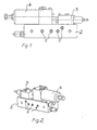
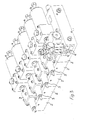
- the module 1 is shown, which consists of a module board 2 exists, to which a connection valve 3 and a pressure control valve 4 are applied are.
- Channels 5 are introduced in the module board 2.
- the channels are like this led that the boards can be put together and their channels with each other are connectable.
- These channels 5 can optionally be determined as the working channel will also serve as pure through channels and are therefore can be used for various purposes.
- the number of channels is different and adapted to the purposes.
- the channels 5 can both as Hydraulic channels, which is mostly the case, as well as a pneumatic channel and can also be designed as an electrical channel to allow control to vary.
- This module 3 is the combination of five modules by joining of their boards. This module unit only requires a hydraulic one Connection 6. If such a module unit can be mounted on a pallet five different working cylinders 7 can be controlled. Channels 5 are interlinked and are created by the outer modules completed. Likewise, only the module with a hydraulic connection is provided that is the first to initiate the functions. This module must not always be one of the external modules, but can be on everyone anywhere in the row arrangement.
- FIG. 4 shows the assembly of five modules, as in Fig. 3 shown underlying.
- the module unit is designed so that in one Level all connection valves 3 and in the other level all pressure control valves 4 lie. Outside of this module unit are the working cylinders 7 which the clamping elements for holding and supporting those mounted on the pallet Workpieces are assigned.
- the hydraulic feed line 6 is only available once for the module unit. This is only when moving the pallet to other machine tables to decouple this one supply line.
- the hydraulic connection 6 is here assigned to the first module and provided with a filter 8, which has the task keep the hydraulics free of foreign objects.
- a check valve 9 is arranged in the hydraulic connection. This Check valve is designed as an unlockable valve, so that it once the The pressure in the system has an effect if the pressure in the supply line drops to maintain and on the other hand if necessary by unlocking the Relieve pressure.
- the remaining modules are now dependent, which is adapted to the work processes.
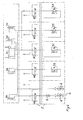
- the working cylinders are loaded 7 A-E, of which cylinder A for placing on the workpiece, cylinder B for center, cylinders C and D for clamping and cylinder D for blocking the Serve workpiece.
- the hydraulic system passes through filter 8 to the check valve 9 and from there to the pressure control valve 4A.
- This Pressure control valve 4A is limited to the pressure from the working cylinder 7A is needed.
- the working cylinder 7A thus responds.
- This higher pressure is used to control the connection valves 3 in predetermined order required.
- the sequence valves 3 are open different pressures for switching through set. This circuit takes place in the order in which they should respond.
- the sequence valves 3 are also designed so that they are only in ascending order Address print sequence. This means that a subsequent connecting valve can always only respond when the connecting valve in front of it has switched through.
- the hydraulic connection for each subsequent connecting valve is always there in the output hydraulic line of the previous connection valve.
- Fig. 4 speaks to a certain, but lowest in the series pressure (50 bar) designed connecting valve 3B first and switches to it Pressure relief valve 4B through which in turn the working cylinder 7B in Action.
- This means that the connecting valve 3B only then the line for the subsequent connecting valve 3C, which responds at 70 bar, and in turn releases the line for the next one that responds at 90 bar etc. up to the last connecting valve 3E in the row, which is set to 110 bar is set.
- connection valves 3 With the connection of one of the connection valves 3 once the hydraulic flow to the downstream pressure control valves 4 free given and the next in the specified order Activation valve activated.
- the dependence of the ascending print sequence for the sequence valves 3 is required to the order of response of the Determine working cylinder.
- the pressure control valves 4 are independent of this ascending pressure sequence and can be assigned to any different pressures, each of the downstream working cylinders can be determined.
- This module unit can be composed of any number of modules. Several module units can also be arranged on a pallet. The advantage is that the module unit can be accommodated in the smallest space and also only requires one connection for the hydraulics. As before mentioned, the module boards 2 have the through channels 5, which also can be pneumatically or electrically actuated. This requires corresponding connection couplings between the individual module units. In addition, the connection valves 3 with additional switching elements for the Pneumatic and / or electrical equipment. Thus, the Connection valves 3 possible in all types mentioned. This offers the advantage of Control independent of the system pressure.
Landscapes
- Engineering & Computer Science (AREA)
- Mechanical Engineering (AREA)
- Physics & Mathematics (AREA)
- Fluid Mechanics (AREA)
- General Engineering & Computer Science (AREA)
- Fluid-Pressure Circuits (AREA)
Abstract
Description
- Fig. 1
- zeigt die Seitenansicht eines Moduls
- Fig. 2
- zeigt das Modul in der Perspektive
- Fig. 3
- zeigt den Zusammenschluss von fünf Modulen
- Fig. 4
- zeigt die Zusammenschaltung und Verknüpfung der fünf Module
Claims (9)
- Modulsystem zur Ansteuerung und Betätigung von hydraulisch wirkenden Arbeitszylindern, die Vorrichtungen zum Spannen von Werkstücken zugeordnet und auf Paletten oder Arbeitstischen montierbar sind und die unterschiedliche Funktionen mit unterschiedlichen Arbeitsdrücken durchführen, dadurch gekennzeichnet, daß das Modul (1) aus einer Platine (2) besteht auf der ein Zuschaltventil (3) und ein Druckregelventil (4) angeordnet sind und daß in der Platine (2) mehrere Kanäle (5) geführt sind, die wahlweise zu Arbeits- oder Durchgangskanäle bestimmbar sind.
- Modulsystem nach Anspruch 1, dadurch gekennzeichnet, daß die Module (1) zu einer Moduleinheit, bestehend aus mehreren Modulen zusammenfügbar sind und daß die Kanäle (5) untereinander verbindbar sind.
- Modulsystem nach Anspruch 1 u. 2, dadurch gekennzeichnet, daß die aus mehreren Modulen (1) gebildete Moduleinheit mit vorbestimmten Kanälen (5) so verbunden ist, daß die zugehörigen Zuschaltventile (3) in vorgegebener Reihenfolge ansteuerbar sind.
- Modulsystem nach Anspruch 3, dadurch gekennzeichnet, daß das Durchschalten eines jeden folgenden Zuschaltventils von dem Durchschalten des vorherigen Zuschaltventils abhängig ist.
- Modulsystem nach Anspruch 1-4, dadurch gekennzeichnet, daß die zu einer Moduleinheit zusammen geschalteten Module (1) mit nur einem Hygraulikanschluss versehen sind, der dem Modul in der Reihe zugeordnet ist, das die erste Durchschaltung vollzieht.
- Modulsystem nach Anspruch 1-5, dadurch gekennzeichnet, daß die den Modulen (1) zugeordneten Zuschaltventile (3) in der Reihe ihrer Zuordnung ansteuerbar sind, in Abhängigkeit der Durchschaltung des jeweils in der Reihe zuvor liegenden Zuschaltventils.
- Modulsystem nach Anspruch 1-6, dadurch gekennzeichnet, daß die Zuschaltventile (3) druckabhängig ansteuerbar sind, und zwar in aufsteigender Druckfolge in ihrer Reihenschaltung.
- Modulsystem nach Anspruch 1, dadurch gekennzeichnet, daß mindest zwei der Durchgangskanäle (5) pneumatisch beaufschlagt sind und daß die Zuschaltventile über zugehörige pneumatisch wirkende Schaltelemente ansteuerbar sind.
- Modulsystem nach Anspruch 1, dadurch gekennzeichnet, daß in mindest zwei Durchgangskanälen (5) eine elektrische Leitung verlegt und zwischen je zwei Modulen (1) in diesen Kanälen ein elektrisches Kupplungssystem vorgesehen ist und daß die Zuschaltventile (3) mit elektrischen Steuerelementen versehen sind, so daß ihre Ansteuerung elektrisch vollziehbar ist.
Applications Claiming Priority (2)
| Application Number | Priority Date | Filing Date | Title |
|---|---|---|---|
| DE10023216A DE10023216A1 (de) | 2000-05-12 | 2000-05-12 | Modulsystem für Hydraulikelemente |
| DE10023216 | 2000-05-12 |
Publications (3)
| Publication Number | Publication Date |
|---|---|
| EP1154163A2 true EP1154163A2 (de) | 2001-11-14 |
| EP1154163A3 EP1154163A3 (de) | 2003-11-12 |
| EP1154163B1 EP1154163B1 (de) | 2005-12-14 |
Family
ID=7641742
Family Applications (1)
| Application Number | Title | Priority Date | Filing Date |
|---|---|---|---|
| EP01111539A Expired - Lifetime EP1154163B1 (de) | 2000-05-12 | 2001-05-11 | Modulsystem für Hydraulikelemente |
Country Status (4)
| Country | Link |
|---|---|
| EP (1) | EP1154163B1 (de) |
| AT (1) | ATE313015T1 (de) |
| DE (2) | DE10023216A1 (de) |
| ES (1) | ES2253299T3 (de) |
Cited By (3)
| Publication number | Priority date | Publication date | Assignee | Title |
|---|---|---|---|---|
| DE102004027467A1 (de) * | 2004-06-04 | 2005-12-29 | Audi Ag | Ventil-Anordnung für ein Druckölsystem |
| CN103406846A (zh) * | 2013-07-17 | 2013-11-27 | 上海福太隆汽车电子科技有限公司 | 一种产品工装的气缸电控系统 |
| CN113153848A (zh) * | 2021-04-19 | 2021-07-23 | 无锡贝斯特精机股份有限公司 | 具有预压紧功能的液压系统 |
Families Citing this family (3)
| Publication number | Priority date | Publication date | Assignee | Title |
|---|---|---|---|---|
| DE102005051363A1 (de) | 2005-10-25 | 2007-04-26 | Ludwig Ehrhardt Gmbh | Modulsystem zur wahlfreien Ansteuerung von Hydraulikelementen |
| DE102011086853A1 (de) * | 2011-11-22 | 2013-05-23 | Marcel Sanwald | Nullpunktspannsystem |
| CN115533749A (zh) * | 2022-10-31 | 2022-12-30 | 徐州阿马凯液压技术有限公司 | 一种通用液压阀珩磨夹具 |
Family Cites Families (2)
| Publication number | Priority date | Publication date | Assignee | Title |
|---|---|---|---|---|
| US5533334A (en) * | 1992-04-08 | 1996-07-09 | Kabushiki Kaisha Komatsu Seisakusho | Pressurized fluid supply system |
| DE19959569A1 (de) * | 1999-12-10 | 2001-06-13 | Mannesmann Rexroth Ag | Hydraulische Steueranordnung zum Steuern von zwei unterschiedlich hohen Drücken an einem hydraulischen Verbraucher, insbesondere von zwei unterschiedlich hohen Spanndrücken zum Halten eines Werkstücks in einer Werkzeugmaschine |
-
2000
- 2000-05-12 DE DE10023216A patent/DE10023216A1/de not_active Withdrawn
-
2001
- 2001-05-11 EP EP01111539A patent/EP1154163B1/de not_active Expired - Lifetime
- 2001-05-11 ES ES01111539T patent/ES2253299T3/es not_active Expired - Lifetime
- 2001-05-11 AT AT01111539T patent/ATE313015T1/de not_active IP Right Cessation
- 2001-05-11 DE DE50108356T patent/DE50108356D1/de not_active Expired - Fee Related
Non-Patent Citations (1)
| Title |
|---|
| None |
Cited By (6)
| Publication number | Priority date | Publication date | Assignee | Title |
|---|---|---|---|---|
| DE102004027467A1 (de) * | 2004-06-04 | 2005-12-29 | Audi Ag | Ventil-Anordnung für ein Druckölsystem |
| DE102004027467B4 (de) * | 2004-06-04 | 2006-04-13 | Audi Ag | Ventil-Anordnung für ein Druckölsystem |
| CN103406846A (zh) * | 2013-07-17 | 2013-11-27 | 上海福太隆汽车电子科技有限公司 | 一种产品工装的气缸电控系统 |
| CN103406846B (zh) * | 2013-07-17 | 2016-06-08 | 上海福太隆汽车电子科技有限公司 | 一种产品工装的气缸电控系统 |
| CN113153848A (zh) * | 2021-04-19 | 2021-07-23 | 无锡贝斯特精机股份有限公司 | 具有预压紧功能的液压系统 |
| CN113153848B (zh) * | 2021-04-19 | 2023-03-28 | 无锡贝斯特精机股份有限公司 | 具有预压紧功能的液压系统 |
Also Published As
| Publication number | Publication date |
|---|---|
| EP1154163B1 (de) | 2005-12-14 |
| DE10023216A1 (de) | 2001-11-15 |
| ATE313015T1 (de) | 2005-12-15 |
| DE50108356D1 (de) | 2006-01-19 |
| ES2253299T3 (es) | 2006-06-01 |
| EP1154163A3 (de) | 2003-11-12 |
Similar Documents
| Publication | Publication Date | Title |
|---|---|---|
| EP0968372B1 (de) | Ventilanordnung | |
| DE2704869C3 (de) | In modularer Bauweise aus gleichen, logische Schaltungselemente enthaltenden Baugruppen zusammengesetzte fluidische Steuerschaltung | |
| EP0608245A1 (de) | Elektro-pneumatische steuereinrichtung. | |
| DE2631876A1 (de) | Trennventil | |
| EP0555857B1 (de) | Hinterradlenkvorrichtung | |
| WO2019072328A1 (de) | Ventilanordnung und steuerungsverfahren | |
| DE2232627A1 (de) | Druckmittelverteiler | |
| DE60217187T2 (de) | Druckluftversorgungsgerät mit einem Verdichter | |
| EP1118800A2 (de) | Steuereinrichtung für ein Getriebe | |
| DE3502773A1 (de) | Fluidzuleitungsventil | |
| EP1154163A2 (de) | Modulsystem für Hydraulikelemente | |
| DE4243289C1 (de) | Steuergerät für ein hydraulisches Schreitausbaugestell | |
| DE3232367A1 (de) | Einrichtung zum anschluss einer auf einer werkstueckpalette angeordneten hydraulischen spannvorrichtung | |
| DE19801234C2 (de) | Ventileinheit | |
| DE10153784B4 (de) | Modulares Steuersystem für eine Ladevorrichtung mit gezielter Sauggreifersteuerung | |
| DE69918577T2 (de) | Stützvorrichtung | |
| DE3840478C2 (de) | Einrichtung zur Notbetätigung hydraulischer Ausbaueinheiten bei elektrohydraulischen Ausbausteuerungen | |
| DE102015221259A1 (de) | Ventilmodul und Ventilanordnung | |
| DE29903693U1 (de) | Hydraulische Werkstückspannvorrichtung | |
| DE3524790C2 (de) | ||
| DE2640185B2 (de) | Mehrfachsteuergerät für hydraulischen Schreitausbau | |
| DE2062156A1 (de) | Sicherheitssteuerung für mit flüssigen Servomitteln betriebene Maschinen, insbesondere für Pressen | |
| DE19909920A1 (de) | Sicherheitsschaltung für einen pneumatischen Motor | |
| DE2303433B2 (de) | Anordnung für hydraulische Schaltungen des Untertagebergbaus, z.B. für den hydraulischen Strebausbau | |
| DE2905505C2 (de) |
Legal Events
| Date | Code | Title | Description |
|---|---|---|---|
| PUAI | Public reference made under article 153(3) epc to a published international application that has entered the european phase |
Free format text: ORIGINAL CODE: 0009012 |
|
| AK | Designated contracting states |
Kind code of ref document: A2 Designated state(s): AT BE CH CY DE DK ES FI FR GB GR IE IT LI LU MC NL PT SE TR |
|
| AX | Request for extension of the european patent |
Free format text: AL;LT;LV;MK;RO;SI |
|
| RIN1 | Information on inventor provided before grant (corrected) |
Inventor name: LEHR, ADOLF Inventor name: EHRHARDT, WINFRIED |
|
| RIN1 | Information on inventor provided before grant (corrected) |
Inventor name: LEHR, ADOLF Inventor name: EHRHARDT, WINFRIED, DR. |
|
| PUAL | Search report despatched |
Free format text: ORIGINAL CODE: 0009013 |
|
| AK | Designated contracting states |
Kind code of ref document: A3 Designated state(s): AT BE CH CY DE DK ES FI FR GB GR IE IT LI LU MC NL PT SE TR |
|
| AX | Request for extension of the european patent |
Extension state: AL LT LV MK RO SI |
|
| 17P | Request for examination filed |
Effective date: 20031010 |
|
| 17Q | First examination report despatched |
Effective date: 20040204 |
|
| RAP1 | Party data changed (applicant data changed or rights of an application transferred) |
Owner name: LUDWIG EHRHARDT GMBH |
|
| AKX | Designation fees paid |
Designated state(s): AT BE CH CY DE DK ES FI FR GB GR IE IT LI LU MC NL PT SE TR |
|
| GRAP | Despatch of communication of intention to grant a patent |
Free format text: ORIGINAL CODE: EPIDOSNIGR1 |
|
| GRAS | Grant fee paid |
Free format text: ORIGINAL CODE: EPIDOSNIGR3 |
|
| GRAA | (expected) grant |
Free format text: ORIGINAL CODE: 0009210 |
|
| AK | Designated contracting states |
Kind code of ref document: B1 Designated state(s): AT BE CH CY DE DK ES FI FR GB GR IE IT LI LU MC NL PT SE TR |
|
| PG25 | Lapsed in a contracting state [announced via postgrant information from national office to epo] |
Ref country code: NL Free format text: LAPSE BECAUSE OF FAILURE TO SUBMIT A TRANSLATION OF THE DESCRIPTION OR TO PAY THE FEE WITHIN THE PRESCRIBED TIME-LIMIT Effective date: 20051214 Ref country code: FI Free format text: LAPSE BECAUSE OF FAILURE TO SUBMIT A TRANSLATION OF THE DESCRIPTION OR TO PAY THE FEE WITHIN THE PRESCRIBED TIME-LIMIT Effective date: 20051214 Ref country code: IE Free format text: LAPSE BECAUSE OF FAILURE TO SUBMIT A TRANSLATION OF THE DESCRIPTION OR TO PAY THE FEE WITHIN THE PRESCRIBED TIME-LIMIT Effective date: 20051214 |
|
| REG | Reference to a national code |
Ref country code: GB Ref legal event code: FG4D Free format text: NOT ENGLISH |
|
| REG | Reference to a national code |
Ref country code: CH Ref legal event code: EP |
|
| REG | Reference to a national code |
Ref country code: IE Ref legal event code: FG4D Free format text: LANGUAGE OF EP DOCUMENT: GERMAN |
|
| REF | Corresponds to: |
Ref document number: 50108356 Country of ref document: DE Date of ref document: 20060119 Kind code of ref document: P |
|
| GBT | Gb: translation of ep patent filed (gb section 77(6)(a)/1977) |
Effective date: 20060215 |
|
| PG25 | Lapsed in a contracting state [announced via postgrant information from national office to epo] |
Ref country code: GR Free format text: LAPSE BECAUSE OF FAILURE TO SUBMIT A TRANSLATION OF THE DESCRIPTION OR TO PAY THE FEE WITHIN THE PRESCRIBED TIME-LIMIT Effective date: 20060314 Ref country code: SE Free format text: LAPSE BECAUSE OF FAILURE TO SUBMIT A TRANSLATION OF THE DESCRIPTION OR TO PAY THE FEE WITHIN THE PRESCRIBED TIME-LIMIT Effective date: 20060314 Ref country code: DK Free format text: LAPSE BECAUSE OF FAILURE TO SUBMIT A TRANSLATION OF THE DESCRIPTION OR TO PAY THE FEE WITHIN THE PRESCRIBED TIME-LIMIT Effective date: 20060314 |
|
| PG25 | Lapsed in a contracting state [announced via postgrant information from national office to epo] |
Ref country code: PT Free format text: LAPSE BECAUSE OF FAILURE TO SUBMIT A TRANSLATION OF THE DESCRIPTION OR TO PAY THE FEE WITHIN THE PRESCRIBED TIME-LIMIT Effective date: 20060515 |
|
| PG25 | Lapsed in a contracting state [announced via postgrant information from national office to epo] |
Ref country code: BE Free format text: LAPSE BECAUSE OF NON-PAYMENT OF DUE FEES Effective date: 20060531 Ref country code: MC Free format text: LAPSE BECAUSE OF NON-PAYMENT OF DUE FEES Effective date: 20060531 |
|
| NLV1 | Nl: lapsed or annulled due to failure to fulfill the requirements of art. 29p and 29m of the patents act | ||
| REG | Reference to a national code |
Ref country code: ES Ref legal event code: FG2A Ref document number: 2253299 Country of ref document: ES Kind code of ref document: T3 |
|
| ET | Fr: translation filed | ||
| REG | Reference to a national code |
Ref country code: IE Ref legal event code: FD4D |
|
| PLBE | No opposition filed within time limit |
Free format text: ORIGINAL CODE: 0009261 |
|
| STAA | Information on the status of an ep patent application or granted ep patent |
Free format text: STATUS: NO OPPOSITION FILED WITHIN TIME LIMIT |
|
| 26N | No opposition filed |
Effective date: 20060915 |
|
| BERE | Be: lapsed |
Owner name: LUDWIG EHRHARDT G.M.B.H. Effective date: 20060531 |
|
| PG25 | Lapsed in a contracting state [announced via postgrant information from national office to epo] |
Ref country code: LU Free format text: LAPSE BECAUSE OF NON-PAYMENT OF DUE FEES Effective date: 20060511 Ref country code: TR Free format text: LAPSE BECAUSE OF FAILURE TO SUBMIT A TRANSLATION OF THE DESCRIPTION OR TO PAY THE FEE WITHIN THE PRESCRIBED TIME-LIMIT Effective date: 20051214 |
|
| PGFP | Annual fee paid to national office [announced via postgrant information from national office to epo] |
Ref country code: CH Payment date: 20080523 Year of fee payment: 8 Ref country code: DE Payment date: 20080531 Year of fee payment: 8 Ref country code: ES Payment date: 20080523 Year of fee payment: 8 |
|
| PGFP | Annual fee paid to national office [announced via postgrant information from national office to epo] |
Ref country code: AT Payment date: 20080521 Year of fee payment: 8 |
|
| PGFP | Annual fee paid to national office [announced via postgrant information from national office to epo] |
Ref country code: IT Payment date: 20080524 Year of fee payment: 8 |
|
| PG25 | Lapsed in a contracting state [announced via postgrant information from national office to epo] |
Ref country code: CY Free format text: LAPSE BECAUSE OF FAILURE TO SUBMIT A TRANSLATION OF THE DESCRIPTION OR TO PAY THE FEE WITHIN THE PRESCRIBED TIME-LIMIT Effective date: 20051214 |
|
| PGFP | Annual fee paid to national office [announced via postgrant information from national office to epo] |
Ref country code: GB Payment date: 20080522 Year of fee payment: 8 |
|
| REG | Reference to a national code |
Ref country code: CH Ref legal event code: PL |
|
| GBPC | Gb: european patent ceased through non-payment of renewal fee |
Effective date: 20090511 |
|
| PG25 | Lapsed in a contracting state [announced via postgrant information from national office to epo] |
Ref country code: LI Free format text: LAPSE BECAUSE OF NON-PAYMENT OF DUE FEES Effective date: 20090531 Ref country code: CH Free format text: LAPSE BECAUSE OF NON-PAYMENT OF DUE FEES Effective date: 20090531 Ref country code: AT Free format text: LAPSE BECAUSE OF NON-PAYMENT OF DUE FEES Effective date: 20090511 |
|
| REG | Reference to a national code |
Ref country code: FR Ref legal event code: ST Effective date: 20100129 |
|
| PG25 | Lapsed in a contracting state [announced via postgrant information from national office to epo] |
Ref country code: FR Free format text: LAPSE BECAUSE OF NON-PAYMENT OF DUE FEES Effective date: 20090602 |
|
| PGFP | Annual fee paid to national office [announced via postgrant information from national office to epo] |
Ref country code: FR Payment date: 20080519 Year of fee payment: 8 |
|
| PG25 | Lapsed in a contracting state [announced via postgrant information from national office to epo] |
Ref country code: GB Free format text: LAPSE BECAUSE OF NON-PAYMENT OF DUE FEES Effective date: 20090511 |
|
| PG25 | Lapsed in a contracting state [announced via postgrant information from national office to epo] |
Ref country code: DE Free format text: LAPSE BECAUSE OF NON-PAYMENT OF DUE FEES Effective date: 20091201 |
|
| REG | Reference to a national code |
Ref country code: ES Ref legal event code: FD2A Effective date: 20090512 |
|
| PG25 | Lapsed in a contracting state [announced via postgrant information from national office to epo] |
Ref country code: ES Free format text: LAPSE BECAUSE OF NON-PAYMENT OF DUE FEES Effective date: 20090512 |
|
| PG25 | Lapsed in a contracting state [announced via postgrant information from national office to epo] |
Ref country code: IT Free format text: LAPSE BECAUSE OF NON-PAYMENT OF DUE FEES Effective date: 20090511 |