EP1153806A2 - Gehäuse für ein Gassackmodul und Insassen-Sicherheitsvorrichtung - Google Patents
Gehäuse für ein Gassackmodul und Insassen-Sicherheitsvorrichtung Download PDFInfo
- Publication number
- EP1153806A2 EP1153806A2 EP01109468A EP01109468A EP1153806A2 EP 1153806 A2 EP1153806 A2 EP 1153806A2 EP 01109468 A EP01109468 A EP 01109468A EP 01109468 A EP01109468 A EP 01109468A EP 1153806 A2 EP1153806 A2 EP 1153806A2
- Authority
- EP
- European Patent Office
- Prior art keywords
- housing
- flap
- side wall
- housing according
- projection
- Prior art date
- Legal status (The legal status is an assumption and is not a legal conclusion. Google has not performed a legal analysis and makes no representation as to the accuracy of the status listed.)
- Granted
Links
- 238000005266 casting Methods 0.000 claims description 2
- 230000015572 biosynthetic process Effects 0.000 claims 1
- 238000004519 manufacturing process Methods 0.000 description 5
- 238000001746 injection moulding Methods 0.000 description 4
- 230000004913 activation Effects 0.000 description 2
- 238000005516 engineering process Methods 0.000 description 2
- 238000002347 injection Methods 0.000 description 2
- 239000007924 injection Substances 0.000 description 2
- 241000191291 Abies alba Species 0.000 description 1
- 229910000831 Steel Inorganic materials 0.000 description 1
- 238000005520 cutting process Methods 0.000 description 1
- 230000002349 favourable effect Effects 0.000 description 1
- 238000010304 firing Methods 0.000 description 1
- 238000003780 insertion Methods 0.000 description 1
- 230000037431 insertion Effects 0.000 description 1
- 230000007246 mechanism Effects 0.000 description 1
- 230000000717 retained effect Effects 0.000 description 1
- 239000000243 solution Substances 0.000 description 1
- 125000006850 spacer group Chemical group 0.000 description 1
- 239000010959 steel Substances 0.000 description 1
Images




Classifications
-
- B—PERFORMING OPERATIONS; TRANSPORTING
- B60—VEHICLES IN GENERAL
- B60R—VEHICLES, VEHICLE FITTINGS, OR VEHICLE PARTS, NOT OTHERWISE PROVIDED FOR
- B60R21/00—Arrangements or fittings on vehicles for protecting or preventing injuries to occupants or pedestrians in case of accidents or other traffic risks
- B60R21/02—Occupant safety arrangements or fittings, e.g. crash pads
- B60R21/16—Inflatable occupant restraints or confinements designed to inflate upon impact or impending impact, e.g. air bags
- B60R21/20—Arrangements for storing inflatable members in their non-use or deflated condition; Arrangement or mounting of air bag modules or components
- B60R21/213—Arrangements for storing inflatable members in their non-use or deflated condition; Arrangement or mounting of air bag modules or components in vehicle roof frames or pillars
-
- B—PERFORMING OPERATIONS; TRANSPORTING
- B60—VEHICLES IN GENERAL
- B60R—VEHICLES, VEHICLE FITTINGS, OR VEHICLE PARTS, NOT OTHERWISE PROVIDED FOR
- B60R21/00—Arrangements or fittings on vehicles for protecting or preventing injuries to occupants or pedestrians in case of accidents or other traffic risks
- B60R21/02—Occupant safety arrangements or fittings, e.g. crash pads
- B60R21/16—Inflatable occupant restraints or confinements designed to inflate upon impact or impending impact, e.g. air bags
- B60R21/20—Arrangements for storing inflatable members in their non-use or deflated condition; Arrangement or mounting of air bag modules or components
- B60R21/217—Inflation fluid source retainers, e.g. reaction canisters; Connection of bags, covers, diffusers or inflation fluid sources therewith or together
- B60R21/2176—Inflation fluid source retainers, e.g. reaction canisters; Connection of bags, covers, diffusers or inflation fluid sources therewith or together the air bag components being completely enclosed in a soft or semi-rigid housing or cover
Definitions
- the invention relates to a housing for a side airbag Vehicle occupant safety device, with a first and a second Side wall and one connecting the two side walls and in one piece with this trained footbridge.
- the invention further relates to an occupant safety device with a housing according to the invention.
- the invention has for its object a versatile To create gas bag housing that is easy to manufacture and out as few individual parts as possible.
- a housing of the type mentioned at the outset by that at least one projection is formed on the first side wall, which with the first side wall is formed in one piece and towards the second Side wall extends that a recess is provided in the second side wall is at least in the area between the projection and the web extends, and that a flap is integrally formed on the housing, which Recess in the second side wall after pivoting the flap into the can at least partially close the closed position.
- Training of projections in a side wall allows the geometry of the housing adapt to many requirements.
- the housing can be made in one piece in a known Injection molding technology can be manufactured using a core.
- About the Flap molded during injection molding allows the housing to be in the area close the recess later to protect the gas bag from dirt and To protect damage. Since the housing consists of only one part, there are no further manufacturing steps for assembling the housing, it must only the flap can be closed.
- the housing according to the invention is therefore much easier to manufacture than e.g.
- the projection a through opening and forms a passage through the housing.
- a passage in the gas bag housing offers the possibility of components that are to extend into the vehicle interior to attach to the roof frame.
- the projection preferably extends to the second side wall, preferably without being integrally connected to it, so that its Walls protect the gas bag from the component that is passed through offer, as a guide for the component and as a spacer for the side walls can serve.
- the implementation extends particularly advantageously perpendicular to Longitudinal axis of the housing to facilitate assembly of the components.
- the longitudinal axis of the housing here is the direction of the greatest longitudinal extension of the Gas bag housing, i.e. along the roof frame.
- the Open up at least one opening, which with the door closed Feed through the housing is aligned. In this way, a safe and create a tight connection that the housing compared to the implementation completes.
- the flap preferably has a fastening element, which at closed flap engages the second side wall and the flap fixed in position.
- the flap has Fastening element that engages the projection when the flap is closed and the flap is fixed in position. In both cases, the fasteners just mold during the injection molding process.
- the fastener on the flap is advantageously a bar that to close the flap only on the inside of the second side wall must be pushed to fix the flap to the housing.
- Closure elements are preferably on at least one side wall molded, which can close the housing. By attaching the two side walls at the end of the housing opposite the web the housing can be closed together until the gas bag is activated hold and protect the gas bag from damage and dirt.
- the Closure elements are designed in a known manner so that the gas bag at its unfolding can easily open the case.
- the invention also relates to an occupant safety device with a housing according to the invention and a side gas bag accommodated therein, the protrusion having a through opening to form a feedthrough and a part attached to a roof frame of a vehicle, such as a luggage net rod or a handle that protrudes through the bushing.
- the housing can be advantageous over at least one of the Fasten bushings to a component or the roof frame.
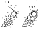
- Figures 1 and 2 show an airbag module 10 with a Housing 12 according to the invention according to a first embodiment.
- the housing 12 has a first side wall 14 and a second side wall 16, each of which is integrally connected at one end to a web 18, which runs the entire length of the housing.
- the web 18 is in the installed condition of the gas bag housing on the top of the housing, while the side walls are essentially vertically downward and one Form the firing channel for the emerging airbag.
- the housing 12, which in the Figures shown in section, has a large longitudinal extension perpendicular to Cutting direction and extends when installed in the vehicle in the essentially from the A to the C pillar along the roof frame.
- the cross section the housing 12 is approximately U-shaped (see FIG. 7).
- the housing 12 serves to accommodate a side gas bag 20, which is in front of it Activation is folded in it. Also arranged in the housing in the Near the web 18 is a so-called gas lance 22, via which the gas bag 20 its activation is filled with gas.
- the two side walls 14, 16 are at their opposite the web 18 Ends connected via known locking mechanisms to the housing to close and the gas bag from damage and dirt protect.
- the first side wall 14 has a projection 24 at at least one point that extends into the interior of the housing 12.
- On web 18 is part of the formed a flap 26 second side wall 16, at the same time the second Side wall 16 in the region of the projection 24 on a recess 30, which is from the end 28 of the projection facing the web 18 to the web 18 extends.
- the flap 26 is integrally formed on the web 18 and can in the direction of Interior of the housing, i.e. to the second side wall 16, folded so that at closed flap 26 the recess 30 and thus the gas bag receiving space within the housing is completely closed.
- the gas bag module 10 in one Holder 32 is mounted, which in turn is attached to the roof frame of a vehicle becomes.
- the holder 32 can also be used to close the flap 26 to keep, so that corresponding fasteners are dispensed with can.
- the flap can also have known devices on the second side wall 16 can be fixed.
- holder 32 there are openings 34 in the region of the protrusion (s) 24 provided, in the screws, not shown, for fastening vehicle parts, e.g. Handles (not shown) can be screwed onto the holder 32. Because of the blind hole at this point, namely the projection 24, molded first side wall 14 is the airbag 20 before contact with the Protected screw end.
- a second embodiment of the invention which is shown in Figures 3 to 4c is shown differs from that just described in that a projection 124 extends substantially to the second side wall 16, with the end of the protrusion 124 facing the second side wall 16 open is, so that a through opening is formed, which has a passage 136 through the Housing 12 forms.
- a projection 124 extends substantially to the second side wall 16, with the end of the protrusion 124 facing the second side wall 16 open is, so that a through opening is formed, which has a passage 136 through the Housing 12 forms.
- the gas bag 20 also has a breakthrough at the corresponding point on what is shown in the drawing by dashed lines.
- a flap 126 is integrally formed on the web 18, while the second side wall 16 has a recess 130 which extends around the bushing 136 and through extends to the web 18.
- flap 126 When flap 126 is closed, it covers the area between the end of the bushing 136 facing the web and the web 18 and leaves the implementation 136 free.
- the walls 138 of the implementation 136 close together with tabs 140, which are formed on the flap 126, when the flap is closed, the interior of the housing 12 and protect the Airbag from dirt and damage.
- the walls 138 can to the second side part 16, because the recess 130 is arranged so that a demolding of the housing from the casting tool is possible.
- Fastening elements 142 allow the flap to be fixed in position on the housing.
- the Fastening elements 142 can be conventional latching elements.
- the flap 126 When assembling the gas bag module, the flap 126 is closed, whereby can also be exploited that the insertion of the Gas bags 20 around the bushing 136 is simplified.
- the housing 12 with closed flap 126 can then, as in the first embodiment shown, mounted in the holder 32 and with this on the vehicle, e.g. at the Roof frame, are attached.
- Figures 4b and 4c show a housing according to the two just Embodiments described, Figure 4b shows the housing as part of a Occupant safety device 127, the housing 12 shown and one Handle 127 'and a luggage net rod 127 "comprises.
- Execution 136 takes e.g. one on Luggage net rod 127 "attached to the roof frame.
- FIGS. A third embodiment of the invention is shown in FIGS.
- the housing 12 described below differs from that previously described above all in that all on the first side wall 14th molded projections are formed as bushings 236, 236 '.
- FIG 6 shows a section along line A-A of Figure 5 through a first Implementation 236.
- Flap 226 integrally formed on web 18.
- the flap 226 has openings 252 (see also Figures 9 to 11), which are congruent when the flap is closed Bushings 236 lie and are in alignment with them, so that the inside of the Housing 12 can be closed, the bushings 236, 236 ' stay free of course.
- recesses 230 in the second Side wall 16 is provided, which are necessary to remove the component from its To be able to demold the injection mold.
- the recess 230 extends as in FIG FIG. 9 can be seen, over an area which includes bushings 236, 236 'and includes the space between the bushings and the web 18.
- the flap 226 has at its end facing away from the web 18 Fastening element 244 in the form of a bar. With the flap closed the bar 244 engages behind the second side wall 16 on the inside of the Housing 12 and fixed in this way the position of the flap 226.
- the flap by a bolt 246, e.g. one Christmas tree clip, attached to the housing 12.
- the implementation 236 can also be used to attach the housing 12 to a vehicle-fixed part fasten.
- Bracket 248 for the gas lance 22 (not shown here) integrally formed.
- This bracket 248 need not extend the entire length of the housing 12.
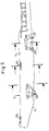
- FIGS. 5, 7 show a section through the housing 12 at one point without bushings.
- the housing 12 is approximately U-shaped at this point, and both side walls 14, 16 are rectilinear.
- Am vom Steg 18 end facing away from the side walls at certain points (see FIGS. 5, 7) closure elements 250, through which the housing 12 in a known manner can be locked.
- Figure 8 shows a section through the housing 12 along the line C-C another implementation 236 '.
- this implementation is elongated to include vehicle-fixed parts, e.g. a handle, to be able to retrofit if the gas bag housing is already on the vehicle is attached.
- FIG. 8 also shows a gas lance 22 inserted into the housing 12 shown.
- Figures 9 and 10 show the flap 226 in the open state.
- a Hinge 254 may be provided, e.g. in the form of a film hinge as in the Figures 6 and 8, or in the form of parallel slots as in Figures 9 and 10.
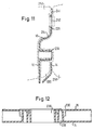
- FIG. 12 shows a section through the different bushings 236.
- the case is due to the Recesses 30, 130, 230 despite the protrusion 24 or the Bushings 136, 236, 236 'resulting undercuts in a known Injection mold 258 (indicated by dashed lines in Figure 11) below
- a core 260 in one piece in a single injection molding process can be made. Since the housing 12 is manufactured with the flaps 26, 126, 226 open , the flaps are not in the mold when removed from the mold Path.
Landscapes
- Engineering & Computer Science (AREA)
- Mechanical Engineering (AREA)
- Air Bags (AREA)
Abstract
Description
Claims (14)
- Gehäuse für einen Seitengassack einer Fahrzeuginsassen-Sicherheitsvorrichtung, mit einer ersten und einer zweiten Seitenwand (14, 16) und einem die beiden Seitenwände (14, 16) verbindenden und einstückig mit diesen ausgebildeten Steg (18), dadurch gekennzeichnet, daß an der ersten Seitenwand (14) wenigstens ein Vorsprung (24; 124) angeformt ist, der mit der ersten Seitenwand (14) einstückig ausgebildet ist und sich in Richtung zur zweiten Seitenwand (16) erstreckt, daß in der zweiten Seitenwand (16) eine Aussparung (30; 130; 230) vorgesehen ist, die sich wenigstens im Bereich zwischen dem Vorsprung (24; 136; 236, 236') und dem Steg (18) erstreckt, und daß am Gehäuse (12) eine Klappe (26; 126; 226) einstückig angeformt ist, die die Aussparung (30; 130; 230) in der zweiten Seitenwand (16) wenigstens teilweise verschließen kann.
- Gehäuse nach Anspruch 1, dadurch gekennzeichnet, daß die Klappe (26; 126; 226) am Steg (18) angeformt ist.
- Gehäuse nach einem der vorhergehenden Ansprüche, dadurch gekennzeichnet, daß sich der Vorsprung (236) bis zur zweiten Seitenwand (16) erstreckt, vorzugsweise ohne mit dieser einstückig oder fest verbunden zu sein.
- Gehäuse nach einem der vorhergehenden Ansprüche, dadurch gekennzeichnet, daß der Vorsprung (136; 236, 236') eine Durchgangsöffnung aufweist und eine Durchführung durch das Gehäuse (12) bildet.
- Gehäuse nach Anspruch 4, dadurch gekennzeichnet, daß sich die Durchführung (136; 236, 236') senkrecht zur Längsachse des Gehäuses (12) erstreckt.
- Gehäuse nach Anspruch 4 oder 5, dadurch gekennzeichnet, daß die Klappe (226) wenigstens eine Öffnung (252) aufweist, die bei geschlossener Klappe mit der Durchführung (236, 236') durch das Gehäuse (12) fluchtet.
- Gehäuse nach einem der vorhergehenden Ansprüche, dadurch gekennzeichnet, daß die Klappe (226) ein Befestigungselement (244) aufweist, das bei geschlossener Klappe (226) an der zweiten Seitenwand (16) angreift und die Klappe (226) lagefixiert.
- Gehäuse nach Anspruch 7, dadurch gekennzeichnet, daß das Befestigungselement (244) eine Leiste ist.
- Gehäuse nach einem der Ansprüche 4 bis 6, dadurch gekennzeichnet, daß die Klappe (126) ein Befestigungselement (142) aufweist, das bei geschlossener Klappe (126) an der Durchführung (136) angreift und die Klappe (126) lagefixiert.
- Gehäuse nach einem der vorhergehenden Ansprüche, dadurch gekennzeichnet, daß es ein Kunststoffgußteil ist.
- Gehäuse nach einem der vorhergehenden Ansprüche, dadurch gekennzeichnet, daß an wenigstens einer Seitenwand (14, 16) Verschlußelemente (250) angeformt sind, die das Gehäuse (12) verschließen können.
- Insassen-Sicherheitsvorrichtung, mit einem Gehäuse nach einem der vorhergehenden Ansprüche und einem im Gehäuse (12) untergebrachten Seitengassack (20), wobei der Vorsprung eine Durchgangsöffnung zur Bildung einer Durchführung aufweist und ein an einem Dachrahmen befestigtes Teil durch die Durchführung (136; 236) hindurchragt.
- Insassen-Sicherheitsvorrichtung nach Anspruch 12, dadurch gekennzeichnet, daß das Teil eine Gepäcknetzstange oder ein Handgriff ist.
- Insassen-Sicherheitsvorrichtung nach Anspruch 12 oder 13, dadurch gekennzeichnet, daß über wenigstens eine der Durchführungen (136; 236) das Gehäuse (12) an einem Dachrahmen oder an einem daran angeordneten Teil befestigbar ist.
Applications Claiming Priority (2)
| Application Number | Priority Date | Filing Date | Title |
|---|---|---|---|
| DE20008543U DE20008543U1 (de) | 2000-05-12 | 2000-05-12 | Gehäuse für ein Gassackmodul und Insassen-Sicherheitsvorrichtung |
| DE20008543U | 2000-05-12 |
Publications (3)
| Publication Number | Publication Date |
|---|---|
| EP1153806A2 true EP1153806A2 (de) | 2001-11-14 |
| EP1153806A3 EP1153806A3 (de) | 2003-11-19 |
| EP1153806B1 EP1153806B1 (de) | 2006-05-31 |
Family
ID=7941411
Family Applications (1)
| Application Number | Title | Priority Date | Filing Date |
|---|---|---|---|
| EP20010109468 Expired - Lifetime EP1153806B1 (de) | 2000-05-12 | 2001-04-24 | Gehäuse für ein Gassackmodul und Insassen-Sicherheitsvorrichtung |
Country Status (3)
| Country | Link |
|---|---|
| EP (1) | EP1153806B1 (de) |
| DE (2) | DE20008543U1 (de) |
| ES (1) | ES2265371T3 (de) |
Cited By (1)
| Publication number | Priority date | Publication date | Assignee | Title |
|---|---|---|---|---|
| US20170072894A1 (en) * | 2015-09-11 | 2017-03-16 | Toyota Jidosha Kabushiki Kaisha | Rear seat side airbag device |
Families Citing this family (2)
| Publication number | Priority date | Publication date | Assignee | Title |
|---|---|---|---|---|
| DE10127509A1 (de) | 2001-06-06 | 2003-01-09 | Volkswagen Ag | Gehäuse für ein Airbagmodul |
| JP5133042B2 (ja) * | 2007-12-19 | 2013-01-30 | 芦森工業株式会社 | カーテンエアバッグの展開規制部材及びカーテンエアバッグの配設部構造 |
Citations (1)
| Publication number | Priority date | Publication date | Assignee | Title |
|---|---|---|---|---|
| DE29813692U1 (de) | 1998-07-31 | 1998-10-15 | Dandl, Friedrich, 80538 München | Klemmtafel mit Klemmleiste |
Family Cites Families (6)
| Publication number | Priority date | Publication date | Assignee | Title |
|---|---|---|---|---|
| JP3218966B2 (ja) * | 1996-03-13 | 2001-10-15 | 豊田合成株式会社 | エアバッグ装置を内蔵したガーニッシュ部材 |
| DE19612229A1 (de) * | 1996-03-27 | 1997-10-02 | Bayerische Motoren Werke Ag | Anordnung eines aufblasbaren seitlichen Kopfschutzsystemes in einem Kraftfahrzeug |
| DE19812737A1 (de) * | 1998-03-24 | 1999-05-27 | Autoliv Dev | Seitenairbag mit Energieabsorptionselement |
| DE29806080U1 (de) * | 1998-04-02 | 1998-08-06 | TRW Occupant Restraint Systems GmbH & Co. KG, 73553 Alfdorf | Haltegriffkonsole |
| DE29807098U1 (de) | 1998-04-20 | 1998-08-13 | TRW Occupant Restraint Systems GmbH & Co. KG, 73553 Alfdorf | Gassack-Modul für ein Fahrzeuginsassen-Rückhaltesystem |
| DE29813962U1 (de) | 1998-08-04 | 1998-12-03 | TRW Occupant Restraint Systems GmbH & Co. KG, 73553 Alfdorf | Seitenaufprall-Rückhaltesystem für ein Kraftfahrzeug |
-
2000
- 2000-05-12 DE DE20008543U patent/DE20008543U1/de not_active Expired - Lifetime
-
2001
- 2001-04-24 DE DE50109924T patent/DE50109924D1/de not_active Expired - Lifetime
- 2001-04-24 EP EP20010109468 patent/EP1153806B1/de not_active Expired - Lifetime
- 2001-04-24 ES ES01109468T patent/ES2265371T3/es not_active Expired - Lifetime
Patent Citations (1)
| Publication number | Priority date | Publication date | Assignee | Title |
|---|---|---|---|---|
| DE29813692U1 (de) | 1998-07-31 | 1998-10-15 | Dandl, Friedrich, 80538 München | Klemmtafel mit Klemmleiste |
Cited By (2)
| Publication number | Priority date | Publication date | Assignee | Title |
|---|---|---|---|---|
| US20170072894A1 (en) * | 2015-09-11 | 2017-03-16 | Toyota Jidosha Kabushiki Kaisha | Rear seat side airbag device |
| US9758122B2 (en) * | 2015-09-11 | 2017-09-12 | Toyota Jidosha Kabushiki Kaisha | Rear seat side airbag device |
Also Published As
| Publication number | Publication date |
|---|---|
| ES2265371T3 (es) | 2007-02-16 |
| EP1153806A3 (de) | 2003-11-19 |
| DE50109924D1 (de) | 2006-07-06 |
| DE20008543U1 (de) | 2000-09-21 |
| EP1153806B1 (de) | 2006-05-31 |
Similar Documents
| Publication | Publication Date | Title |
|---|---|---|
| DE602005006113T2 (de) | Modulträger für Fahrzeugtüren, Türanordnung für Kraftfahrzeuge und Verfahren zur Montage des Modulträgers auf einem Türrahmen | |
| EP3325315A1 (de) | Befestiger zum lösbaren verbinden eines paneels an einer struktur, abdeckpaneel für ein airbag und fahrzeug mit einer struktur und einem airbag | |
| DE10025865A1 (de) | Einrichtung zum Fixieren eines Gassacks in seiner gefalteten Lage sowie Seitengassack-Modul | |
| DE202014010120U1 (de) | Abdeckvorrichtung für eine als Durchgang einer Anhängerkupplung genutzte Öffnung eines Fahrzeug-Stoßfängers | |
| WO1999051457A1 (de) | Haltegriffkonsole und baugruppe aus haltegriffkonsole und kopf-seitengassack-modul | |
| DE69912049T2 (de) | Montagevorrichtung für den Türgriff einer Fahrzeugtür | |
| EP0952044A1 (de) | Gassack-Modul für ein Fahrzeuginsassen- Rückhaltesystem und Verfahren zu seiner Herstellung | |
| EP0647756A1 (de) | Band für Türen, Fenster und dergleichen | |
| EP1348585B1 (de) | Verfahrbarer Deckel für Fahrzeugdach sowie Schiebehebedach-Modul | |
| DE102019114304A1 (de) | Fahrzeug mit einer Dichtungsanordnung | |
| EP0097219B1 (de) | Haltegriff od. dgl. für Fahrzeuge | |
| EP1153806B1 (de) | Gehäuse für ein Gassackmodul und Insassen-Sicherheitsvorrichtung | |
| DE69103083T2 (de) | Griffeinheit für ein Fahrzeug und diesbezügliches Verfahren des Zusammenbaues. | |
| DE102006002006B4 (de) | Antriebsträger für ein öffnungsfähiges Fahrzeugdach | |
| EP1800925B1 (de) | Kraftfahrzeugtür mit einer Seitenaufprallschutzeinrichtung | |
| DE19925859B4 (de) | Montagehilfe für eine Kraftfahrzeugtürkonstruktion | |
| WO2001073248A1 (de) | Abdeckglied | |
| DE19720812A1 (de) | Rückspiegelbefestigung | |
| DE29801871U1 (de) | Gassack-Modul für einen Kopfschutz-Gassack | |
| EP0755814A1 (de) | Gegenlagerböckchen für eine Fahrzeugsonnenblende | |
| DE102022211317B4 (de) | Fahrzeugdach mit einem öffnungsfähigen Faltdach mit Spannseilsystem | |
| DE112019002765T5 (de) | Fahrzeugsonnenblende mit tickethalter | |
| DE10259313B3 (de) | Formteil zur Halterung und Versteifung eines laschenförmigen Ausschnittteils in einem flächigen Gut | |
| DE3729027C2 (de) | ||
| DE10324662B4 (de) | Griffbeschlag |
Legal Events
| Date | Code | Title | Description |
|---|---|---|---|
| PUAI | Public reference made under article 153(3) epc to a published international application that has entered the european phase |
Free format text: ORIGINAL CODE: 0009012 |
|
| AK | Designated contracting states |
Kind code of ref document: A2 Designated state(s): AT BE CH CY DE DK ES FI FR GB GR IE IT LI LU MC NL PT SE TR |
|
| AX | Request for extension of the european patent |
Free format text: AL;LT;LV;MK;RO;SI |
|
| PUAL | Search report despatched |
Free format text: ORIGINAL CODE: 0009013 |
|
| AK | Designated contracting states |
Kind code of ref document: A3 Designated state(s): AT BE CH CY DE DK ES FI FR GB GR IE IT LI LU MC NL PT SE TR |
|
| AX | Request for extension of the european patent |
Extension state: AL LT LV MK RO SI |
|
| 17P | Request for examination filed |
Effective date: 20040309 |
|
| AKX | Designation fees paid |
Designated state(s): DE ES FR GB |
|
| GRAP | Despatch of communication of intention to grant a patent |
Free format text: ORIGINAL CODE: EPIDOSNIGR1 |
|
| GRAC | Information related to communication of intention to grant a patent modified |
Free format text: ORIGINAL CODE: EPIDOSCIGR1 |
|
| RBV | Designated contracting states (corrected) |
Designated state(s): DE ES FR IT |
|
| GRAS | Grant fee paid |
Free format text: ORIGINAL CODE: EPIDOSNIGR3 |
|
| GRAA | (expected) grant |
Free format text: ORIGINAL CODE: 0009210 |
|
| RAP1 | Party data changed (applicant data changed or rights of an application transferred) |
Owner name: TRW AUTOMOTIVE GMBH |
|
| AK | Designated contracting states |
Kind code of ref document: B1 Designated state(s): DE ES FR IT |
|
| PG25 | Lapsed in a contracting state [announced via postgrant information from national office to epo] |
Ref country code: IT Free format text: LAPSE BECAUSE OF FAILURE TO SUBMIT A TRANSLATION OF THE DESCRIPTION OR TO PAY THE FEE WITHIN THE PRESCRIBED TIME-LIMIT;WARNING: LAPSES OF ITALIAN PATENTS WITH EFFECTIVE DATE BEFORE 2007 MAY HAVE OCCURRED AT ANY TIME BEFORE 2007. THE CORRECT EFFECTIVE DATE MAY BE DIFFERENT FROM THE ONE RECORDED. Effective date: 20060531 |
|
| REF | Corresponds to: |
Ref document number: 50109924 Country of ref document: DE Date of ref document: 20060706 Kind code of ref document: P |
|
| ET | Fr: translation filed | ||
| REG | Reference to a national code |
Ref country code: ES Ref legal event code: FG2A Ref document number: 2265371 Country of ref document: ES Kind code of ref document: T3 |
|
| PLBE | No opposition filed within time limit |
Free format text: ORIGINAL CODE: 0009261 |
|
| STAA | Information on the status of an ep patent application or granted ep patent |
Free format text: STATUS: NO OPPOSITION FILED WITHIN TIME LIMIT |
|
| 26N | No opposition filed |
Effective date: 20070301 |
|
| REG | Reference to a national code |
Ref country code: ES Ref legal event code: FD2A Effective date: 20070425 |
|
| PG25 | Lapsed in a contracting state [announced via postgrant information from national office to epo] |
Ref country code: FR Free format text: LAPSE BECAUSE OF NON-PAYMENT OF DUE FEES Effective date: 20070430 |
|
| PG25 | Lapsed in a contracting state [announced via postgrant information from national office to epo] |
Ref country code: ES Free format text: LAPSE BECAUSE OF NON-PAYMENT OF DUE FEES Effective date: 20070425 |
|
| PGFP | Annual fee paid to national office [announced via postgrant information from national office to epo] |
Ref country code: DE Payment date: 20190430 Year of fee payment: 19 |
|
| REG | Reference to a national code |
Ref country code: DE Ref legal event code: R119 Ref document number: 50109924 Country of ref document: DE |
|
| PG25 | Lapsed in a contracting state [announced via postgrant information from national office to epo] |
Ref country code: DE Free format text: LAPSE BECAUSE OF NON-PAYMENT OF DUE FEES Effective date: 20201103 |