EP1153204B1 - Improved bushing for a jet engine vane - Google Patents
Improved bushing for a jet engine vane Download PDFInfo
- Publication number
- EP1153204B1 EP1153204B1 EP00904406A EP00904406A EP1153204B1 EP 1153204 B1 EP1153204 B1 EP 1153204B1 EP 00904406 A EP00904406 A EP 00904406A EP 00904406 A EP00904406 A EP 00904406A EP 1153204 B1 EP1153204 B1 EP 1153204B1
- Authority
- EP
- European Patent Office
- Prior art keywords
- bushing
- vane
- spindle
- finger
- half portion
- Prior art date
- Legal status (The legal status is an assumption and is not a legal conclusion. Google has not performed a legal analysis and makes no representation as to the accuracy of the status listed.)
- Expired - Lifetime
Links
- 239000000463 material Substances 0.000 claims description 15
- 238000002347 injection Methods 0.000 claims description 4
- 239000007924 injection Substances 0.000 claims description 4
- 239000004033 plastic Substances 0.000 claims description 4
- 239000000203 mixture Substances 0.000 claims 1
- 239000004810 polytetrafluoroethylene Substances 0.000 claims 1
- 229920001343 polytetrafluoroethylene Polymers 0.000 claims 1
- 230000000295 complement effect Effects 0.000 abstract 1
- 238000004519 manufacturing process Methods 0.000 description 5
- 230000006835 compression Effects 0.000 description 2
- 238000007906 compression Methods 0.000 description 2
- 239000000446 fuel Substances 0.000 description 2
- 238000009434 installation Methods 0.000 description 2
- 238000000034 method Methods 0.000 description 2
- 229920003223 poly(pyromellitimide-1,4-diphenyl ether) Polymers 0.000 description 2
- 239000004696 Poly ether ether ketone Substances 0.000 description 1
- 229920004695 VICTREX™ PEEK Polymers 0.000 description 1
- 238000009825 accumulation Methods 0.000 description 1
- 230000000712 assembly Effects 0.000 description 1
- 238000000429 assembly Methods 0.000 description 1
- JUPQTSLXMOCDHR-UHFFFAOYSA-N benzene-1,4-diol;bis(4-fluorophenyl)methanone Chemical compound OC1=CC=C(O)C=C1.C1=CC(F)=CC=C1C(=O)C1=CC=C(F)C=C1 JUPQTSLXMOCDHR-UHFFFAOYSA-N 0.000 description 1
- 238000001746 injection moulding Methods 0.000 description 1
- 238000003754 machining Methods 0.000 description 1
- 229920002530 polyetherether ketone Polymers 0.000 description 1
Images


Classifications
-
- F—MECHANICAL ENGINEERING; LIGHTING; HEATING; WEAPONS; BLASTING
- F16—ENGINEERING ELEMENTS AND UNITS; GENERAL MEASURES FOR PRODUCING AND MAINTAINING EFFECTIVE FUNCTIONING OF MACHINES OR INSTALLATIONS; THERMAL INSULATION IN GENERAL
- F16C—SHAFTS; FLEXIBLE SHAFTS; ELEMENTS OR CRANKSHAFT MECHANISMS; ROTARY BODIES OTHER THAN GEARING ELEMENTS; BEARINGS
- F16C33/00—Parts of bearings; Special methods for making bearings or parts thereof
- F16C33/02—Parts of sliding-contact bearings
- F16C33/04—Brasses; Bushes; Linings
-
- F—MECHANICAL ENGINEERING; LIGHTING; HEATING; WEAPONS; BLASTING
- F01—MACHINES OR ENGINES IN GENERAL; ENGINE PLANTS IN GENERAL; STEAM ENGINES
- F01D—NON-POSITIVE DISPLACEMENT MACHINES OR ENGINES, e.g. STEAM TURBINES
- F01D17/00—Regulating or controlling by varying flow
- F01D17/10—Final actuators
- F01D17/12—Final actuators arranged in stator parts
- F01D17/14—Final actuators arranged in stator parts varying effective cross-sectional area of nozzles or guide conduits
- F01D17/16—Final actuators arranged in stator parts varying effective cross-sectional area of nozzles or guide conduits by means of nozzle vanes
- F01D17/162—Final actuators arranged in stator parts varying effective cross-sectional area of nozzles or guide conduits by means of nozzle vanes for axial flow, i.e. the vanes turning around axes which are essentially perpendicular to the rotor centre line
-
- F—MECHANICAL ENGINEERING; LIGHTING; HEATING; WEAPONS; BLASTING
- F16—ENGINEERING ELEMENTS AND UNITS; GENERAL MEASURES FOR PRODUCING AND MAINTAINING EFFECTIVE FUNCTIONING OF MACHINES OR INSTALLATIONS; THERMAL INSULATION IN GENERAL
- F16C—SHAFTS; FLEXIBLE SHAFTS; ELEMENTS OR CRANKSHAFT MECHANISMS; ROTARY BODIES OTHER THAN GEARING ELEMENTS; BEARINGS
- F16C43/00—Assembling bearings
- F16C43/02—Assembling sliding-contact bearings
Definitions
- the present invention relates generally to a bushing for a jet engine and more specifically to an improved bushing which is less expensive to manufacture and which facilitates shipping and installation of the bushing.
- Jet engines generally include an axial air compressor which supplies compressed air into a combustor.
- the front section of a jet engine includes the axial air compressor.
- the axial air compressor generally includes several consecutive stages, each having a number of stator (stationary) vanes in a shroud and an equal number of rotor (rotating) vanes. Rotor vanes are designed and arranged such that, as the rotor vanes pass by the stator vanes in a particular stage, they take in a volume of air, compress the air and pass this compressed air into the next stage for further compression of the air.
- Stages 1 through 5 of this engine have stator vanes in which the pitch of the vanes is variable.
- the pitch of the variable stator vanes can be adjusted to vary the volume of air intake and thereby control the volume and pressure of the air that is subsequently injected into the combustor to be combined with fuel and ignited.
- the thrust of the engines can thereby be varied and the amount of air can be metered accurately for maximum fuel consumption. This is desirable because it provides the pilot with greater control over the amount of thrust produced within the engine at given engine speeds. For example, when the pilot is bringing the jet in for a landing, he or she can keep the engine running at very high RPMs and vary the pitch of the vanes to generate less thrust within the engine.
- the adjustable vanes allow the pilot to quickly produce thrust without having to adjust the RPMs at which the rotor is rotating.
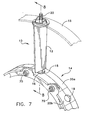
- each vane 10 of the engine described above includes a blade 12 which is rotatably mounted between an inner shroud 14 and an outer shroud 15.
- each stator of a jet engine may include several stages, each having many adjustable vanes. However, for simplicity, only one vane is shown in Fig. 7.
- Vane 10 includes a spindle, partially shown at 16 in Fig.7 and fully shown at 16 in Fig. 1, which is held in place between portions 20a and 20b of inner shroud 14 within aperture 18.
- Vane 10 also includes a drive portion 22 mounted within outer shroud 15.
- a steering mechanism (not shown) is coupled to the drive portion 22 to rotate the vane 10 within the inner shroud 14 and the outer shroud 15.
- a bushing is mounted on spindle 16 before it is mounted between portions 20a and 20b of inner shroud 14.
- a prior art bushing 24 is shown in Figs. 1 and 2. Since the operating temperature of the jet engine can reach 550° F, bushing 24 must be made from a material that can withstand the extremely high temperatures to which it will be subjected. Therefore, bushing 24 is typically formed from a plastic which is capable of withstanding these temperatures.
- One prior art bushing 24 is formed from a plastic material sold by DuPont under the trademark VESPEL. However, this material is not capable of being melt processed, meaning that it cannot be used in an injection molding process to form the bushing 24.
- Bushing 24 is typically formed from a billet of the VESPEL material and is machined to the shape shown in Fig. 1, including a circumferential groove 28 (Fig. 2). The bushing 24 is then cut in half to form parts 26a and 26b. An elastic band 30, made from a high temperature-resistant material, is placed within groove 28 to hold parts 26a and 26b together on spindle 16 until the spindle is mounted to inner shroud 14, as described above.
- bushing 24 Due to the properties of the material used in the manufacture of bushing 24, the requirement that each bushing be separately machined and the requirement for the elastic band 30, bushing 24 is very time consuming and expensive to manufacture. Shipping the bushings from the manufacturer to the end user is problematic because the three-piece bushings are prone to disassembling during shipping, thus requiring extra time for reassembling the bushing before it is installed on the vane 10. Furthermore, since each part 26a and 26b must be held in place on spindle 16 while the elastic band 30 is installed, the installation of bushing 24 on the vane 10 is very time consuming. Since, every time a jet engine is rebuilt, every vane bushing is replaced, the replacement of the bushings adds considerably to the expense and time required to rebuild an engine.
- the present invention is directed to a bushing for a jet engine vane which is injection moldable and therefore is simple and inexpensive to manufacture, and is formed into such a design which enables the bushing to be easily shipped and installed on a jet engine vane.
- a bushing including first and second half portions, each half portion having a substantially semicircular body, an upper end, a lower end, a first side and a second side.
- the first side of the body of each of the first and second half portions have an intermediate finger disposed intermediate the upper and lower ends of the body and the second side of the body of each of the first and second half portions has an upper finger disposed at the upper end of the body and a lower finger disposed at the lower end of the body.
- the upper and lower fingers having a distance therebetween which is no less than the width of the intermediate finger.
- the first and second half portions are constructed and arranged to be snap fit onto a spindle such that the intermediate finger of the first half portion is positioned between the upper and lower fingers of the second half portion and the intermediate finger of the second half portion is positioned between the upper and lower fingers of the first half portion.
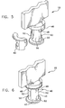
- a vane bushing 40 of the present invention Shown in Figs. 3-6 is a first embodiment of a vane bushing 40 of the present invention.
- Bushing 40 includes two identical parts 42 which are mated together on spindle 16 to form the bushing 40.
- Each part 42 is injection molded in one piece from a material which, while being capable of being melted and injection molded, is also capable of withstanding the very high temperatures experienced in a jet engine once the part is formed.
- the material must also be machinable, since, in some cases, in order to finish the part, each part may be machined to bring it within specific tolerances.
- the material presently contemplated as the preferred material for this application is a combination of approximately 80% of a material sold under the trademark PEEK by Victrex USA, Inc. of West Chester, Pennsylvania, and approximately 20% polytetrafloroethylene (PTFE).
- PEEK polytetrafloroethylene
- each part 42 includes a body portion 44 and a flange portion 46.
- Each body portion 44 includes an upper finger 48 formed at the upper end 60 of one side of body portion 44 proximate flange portion 46 and a lower finger 50 formed at the lower end 62 of the same side of body portion 44 on which upper finger 48 is formed.
- an intermediate finger 52 is formed at a point between the upper end 60 and lower end 62 of body portion 44.
- Upper finger 48 and lower finger 50 have a distance between them which is substantially the same as the width of intermediate finger 52 as defined by the distance between upper edge 54 and lower edge 56 of intermediate finger 52.
- upper finger 48 and lower finger 50 may be greater than the width of intermediate finger 52 to allow for expansion of the parts when the bushing 40 is installed on a spindle and for the accumulation of debris from the normal wear associated with the bushing 40.
- Upper finger 48 has a width, defined by the distance between upper end 60 of body portion 44 and lower edge 66 of upper finger 48, which is substantially the same as the distance between the upper edge 54 of intermediate finger 52 and the upper end 60 of body portion 44.
- Lower finger 50 has a width, defined by the distance between lower end 62 of body portion 44 and upper edge 68 of lower finger 50, which is substantially the same as the distance between the lower edge 56 of intermediate finger 52 and the lower end 62 of body portion 44.
- one part 42 of bushing 40 is shown mounted on a spindle 16 of a vane 10.
- the distance between upper and lower fingers 48 and 50 and intermediate finger 52 is less than the diameter of spindle 16. Therefore, in order to install part 42 onto spindle 16, part 42 is lined up with spindle 16 such that fingers 48, 50 and 52 are in contact with spindle 16, and part 42 is pressed onto spindle 16, causing upper and lower fingers 48 and 50 to be flexed away from intermediate finger 52 in order to allow spindle 16 to pass between upper and lower fingers 48 and 50 and intermediate finger 52.
- upper and lower fingers 48 and 50 and intermediate finger 52 pass beyond the widest part of spindle 16, upper and lower fingers 48 and 50 and intermediate finger 52 snap back into their normal positions, thereby engaging spindle 16 within part 42.
- upper and lower fingers 48 and 50 and intermediate finger 52 span spindle 16 approximately 270°. However, a span of approximately 250° to 280° may be used. The same process is carried out to install the other part 42 on spindle 16.
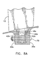
- Figs. 8 and 8A show cross-sectional views, taken along line 8-8 of Fig. 7, of the bushing 40 installed on a spindle 16 of a vane 10 which is mounted to inner shroud 14. Once bushing 42 is installed on spindle 16, bushing 40 and spindle 16 are sandwiched between portion 20a and 20b of inner shroud 14. Portions 20a and 20b are secured together via nut and bolt assemblies 70. This assembly holds vane 10 in place, while allowing it to be rotated about spindle 16.
- both parts 42 of this embodiment are identical, there is no need for preassembling the bushings before they are shipped, and therefore, the prior art problem of having to reassemble bushings that become disassembled during shipping has been eliminated. Furthermore, since each part 42 of bushing 40 can be separately attached to the spindle 16, the need for the elastic band to hold the prior art bushing in place on the spindle 16 has also been eliminated.
Landscapes
- Engineering & Computer Science (AREA)
- General Engineering & Computer Science (AREA)
- Mechanical Engineering (AREA)
- Structures Of Non-Positive Displacement Pumps (AREA)
Applications Claiming Priority (3)
| Application Number | Priority Date | Filing Date | Title |
|---|---|---|---|
| US233902 | 1994-04-28 | ||
| US09/233,902 US6086327A (en) | 1999-01-20 | 1999-01-20 | Bushing for a jet engine vane |
| PCT/US2000/001224 WO2000043642A1 (en) | 1999-01-20 | 2000-01-19 | Improved bushing for a jet engine vane |
Publications (2)
| Publication Number | Publication Date |
|---|---|
| EP1153204A1 EP1153204A1 (en) | 2001-11-14 |
| EP1153204B1 true EP1153204B1 (en) | 2006-07-19 |
Family
ID=22879121
Family Applications (1)
| Application Number | Title | Priority Date | Filing Date |
|---|---|---|---|
| EP00904406A Expired - Lifetime EP1153204B1 (en) | 1999-01-20 | 2000-01-19 | Improved bushing for a jet engine vane |
Country Status (8)
| Country | Link |
|---|---|
| US (2) | US6086327A (enExample) |
| EP (1) | EP1153204B1 (enExample) |
| JP (1) | JP4392733B2 (enExample) |
| AU (1) | AU2616900A (enExample) |
| BR (1) | BR0007612B1 (enExample) |
| CA (2) | CA2652851A1 (enExample) |
| DE (1) | DE60029424T2 (enExample) |
| WO (1) | WO2000043642A1 (enExample) |
Families Citing this family (57)
| Publication number | Priority date | Publication date | Assignee | Title |
|---|---|---|---|---|
| EP1071571B1 (en) * | 1998-04-23 | 2004-10-20 | Nhk Spring Co.Ltd. | Retaining arrangement for a rod member |
| US6708625B1 (en) * | 1999-07-02 | 2004-03-23 | Zeftek, Inc. | Greaseless door lock |
| US6527311B1 (en) | 2000-09-15 | 2003-03-04 | Zeftek, Inc. | Door lock for a railroad car |
| EP1205639A1 (en) * | 2000-11-09 | 2002-05-15 | General Electric Company | Inner shroud retaining system for variable stator vanes |
| USD458285S1 (en) | 2001-06-19 | 2002-06-04 | U-Haul International, Inc. | Bushing |
| US6682299B2 (en) * | 2001-11-15 | 2004-01-27 | General Electric Company | Variable stator vane support arrangement |
| DE10161292A1 (de) | 2001-12-13 | 2003-06-26 | Rolls Royce Deutschland | Lagerring zur Lagerung von Schaufelfüßen von verstellbaren Statorschaufeln im Hochdruckverdichter einer Gasturbine |
| US20030147772A1 (en) * | 2002-02-04 | 2003-08-07 | Tari Taricco | Autoclave construction |
| USD517900S1 (en) * | 2002-04-04 | 2006-03-28 | 420820 Ontario Limited | Bushing |
| US6887035B2 (en) | 2002-10-23 | 2005-05-03 | General Electric Company | Tribologically improved design for variable stator vanes |
| US6887528B2 (en) * | 2002-12-17 | 2005-05-03 | General Electric Company | High temperature abradable coatings |
| US20050003172A1 (en) * | 2002-12-17 | 2005-01-06 | General Electric Company | 7FAstage 1 abradable coatings and method for making same |
| US7163369B2 (en) * | 2003-05-27 | 2007-01-16 | General Electric Company | Variable stator vane bushings and washers |
| US7220098B2 (en) * | 2003-05-27 | 2007-05-22 | General Electric Company | Wear resistant variable stator vane assemblies |
| US7094022B2 (en) * | 2003-05-27 | 2006-08-22 | General Electric Company | Variable stator vane bushings and washers |
| US7207770B2 (en) * | 2003-05-27 | 2007-04-24 | General Electric Company | Variable stator vane bushings and washers |
| US20060029494A1 (en) * | 2003-05-27 | 2006-02-09 | General Electric Company | High temperature ceramic lubricant |
| DE10358421A1 (de) * | 2003-12-13 | 2005-07-07 | Mtu Aero Engines Gmbh | Rotor für eine Turbomaschine |
| GB0504588D0 (en) | 2005-03-05 | 2005-04-13 | Rolls Royce Plc | Pivot ring |
| US7543992B2 (en) * | 2005-04-28 | 2009-06-09 | General Electric Company | High temperature rod end bearings |
| ATE374896T1 (de) * | 2005-05-12 | 2007-10-15 | Stabitec Stanz Biegetechnik Gm | Lager, insbesondere gummilager |
| FR2889242B1 (fr) * | 2005-07-27 | 2007-11-02 | Snecma | Douille pour pivot d'aube a angle de calage variable pour turbomachine |
| DE102005040574A1 (de) * | 2005-08-26 | 2007-03-15 | Rolls-Royce Deutschland Ltd & Co Kg | Spaltkontrollvorrichtung für eine Gasturbine |
| US7510369B2 (en) * | 2005-09-02 | 2009-03-31 | United Technologies Corporation | Sacrificial inner shroud liners for gas turbine engines |
| DE102005042747A1 (de) * | 2005-09-05 | 2007-03-08 | Rolls-Royce Deutschland Ltd & Co Kg | Leitschaufelkranz für eine Gasturbine |
| US20070122274A1 (en) * | 2005-11-29 | 2007-05-31 | General Electric Company | Tip shroud attachment for stator vane |
| US8616558B2 (en) * | 2008-04-03 | 2013-12-31 | GM Global Technology Operations LLC | Tapered interlock retention system for foam overlays |
| DE102008016991B4 (de) * | 2008-04-03 | 2015-10-15 | Hammerlit Gmbh | Ankopplungsvorrichtung zur Verbindung eines Etagenwagens mit einem Transportwagen |
| USD681512S1 (en) * | 2009-05-19 | 2013-05-07 | Larry John Verbowski | Suspension module |
| DE102009038623B4 (de) * | 2009-08-26 | 2012-01-19 | Rolls-Royce Deutschland Ltd & Co Kg | Leitschaufelkranz für den Verdichter einer Fluggasturbine |
| FR2958967B1 (fr) * | 2010-04-14 | 2013-03-15 | Turbomeca | Procede d'adaptation de debit d'air de turbomachine a compresseur centrifuge et diffuseur de mise en oeuvre |
| US8251038B2 (en) * | 2010-07-20 | 2012-08-28 | Caterpillar Inc. | Cylinder head rocker arm stand repair insert |
| FR2964710B1 (fr) * | 2010-09-14 | 2012-08-31 | Snecma | Douille pour aube a calage variable |
| US8915224B2 (en) * | 2010-12-18 | 2014-12-23 | Caterpillar Inc. | Rocker shaft shim |
| US8770930B2 (en) * | 2011-02-09 | 2014-07-08 | Siemens Energy, Inc. | Joining mechanism and method for interlocking modular turbine engine component with a split ring |
| USD698624S1 (en) * | 2011-07-29 | 2014-02-04 | Tser Wen Chou | Blind cord reel bushing |
| USD677198S1 (en) * | 2011-09-29 | 2013-03-05 | Larry John Verbowski | Suspension module with snap ring |
| US9175571B2 (en) | 2012-03-19 | 2015-11-03 | General Electric Company | Connecting system for metal components and CMC components, a turbine blade retaining system and a rotating component retaining system |
| EP2706246B1 (en) * | 2012-09-06 | 2015-12-09 | GGB, Inc. | Interlocking bearing |
| WO2014089642A1 (en) * | 2012-12-11 | 2014-06-19 | Rotacaster Wheel Limited | Axel bush |
| US10385719B2 (en) | 2013-08-28 | 2019-08-20 | United Technologies Corporation | Variable vane bushing |
| US9702411B2 (en) | 2014-04-10 | 2017-07-11 | Roller Bearing Company Of America, Inc. | Bearing assembly with split outer ring having interference fit tabs and method of assembly of bearing |
| DE102014223795A1 (de) * | 2014-11-21 | 2016-05-25 | Robert Bosch Gmbh | Pumpe, insbesondere eine Kraftstoffhochdruckpumpe |
| DE102014223975A1 (de) * | 2014-11-25 | 2016-05-25 | MTU Aero Engines AG | Leitschaufelkranz und Strömungsmaschine |
| FR3029562B1 (fr) * | 2014-12-09 | 2016-12-09 | Snecma | Anneau de commande d’un etage d’aubes a calage variable pour une turbomachine |
| US9863172B2 (en) | 2014-12-11 | 2018-01-09 | Standard Car Truck Company | Railroad car lubricant free door lock |
| JP6774417B2 (ja) | 2015-01-06 | 2020-10-21 | ロタキャスター ホイール リミテッドRotacaster Wheel Limited | ホイールフレーム構成部品 |
| FR3055374B1 (fr) * | 2016-08-23 | 2018-08-03 | Safran Aircraft Engines | Piece d'interface pour reconditionner un anneau de commande d'un compresseur de moteur, et procede de reconditionnement associe |
| DE102016215807A1 (de) * | 2016-08-23 | 2018-03-01 | MTU Aero Engines AG | Innenring für einen Leitschaufelkranz einer Strömungsmaschine |
| DE102017109952A1 (de) * | 2017-05-09 | 2018-11-15 | Rolls-Royce Deutschland Ltd & Co Kg | Rotorvorrichtung einer Strömungsmaschine |
| US10526911B2 (en) * | 2017-06-22 | 2020-01-07 | United Technologies Corporation | Split synchronization ring for variable vane assembly |
| GB201715165D0 (en) | 2017-09-20 | 2017-11-01 | Rolls Royce Plc | Bearing assembly |
| DE102017222209A1 (de) * | 2017-12-07 | 2019-06-13 | MTU Aero Engines AG | Leitschaufelanbindung sowie Strömungsmaschine |
| DE102018210601A1 (de) * | 2018-06-28 | 2020-01-02 | MTU Aero Engines AG | Segmentring zur montage in einer strömungsmaschine |
| DE102018213604B4 (de) | 2018-08-13 | 2025-01-02 | Rolls-Royce Deutschland Ltd & Co Kg | Leitschaufelbaugruppe mit Dichtelement sowie Gasturbinentriebwerk |
| FR3093760B1 (fr) * | 2019-03-15 | 2021-04-02 | Valeo Systemes Thermiques | Module de refroidissement pour véhicule automobile électrique à turbomachine tangentielle |
| USD1039646S1 (en) * | 2020-09-11 | 2024-08-20 | Mcp Ip, Llc | Archery accessory bushing |
Family Cites Families (12)
| Publication number | Priority date | Publication date | Assignee | Title |
|---|---|---|---|---|
| GB757259A (en) * | 1953-06-30 | 1956-09-19 | John B Thompson | Improvements in the manufacture of bearing liners |
| DE2147535A1 (de) * | 1971-09-23 | 1973-03-29 | Akzo Gmbh | Verfahren zur herstellung von cyclischen carbonsaeureimiden |
| JPS5421900B2 (enExample) * | 1973-02-15 | 1979-08-02 | ||
| FR2324935A2 (fr) * | 1974-01-11 | 1977-04-15 | Peugeot & Renault | Bague-coussinet a auto-rattrapage de jeux dans les paliers |
| US3887297A (en) * | 1974-06-25 | 1975-06-03 | United Aircraft Corp | Variable leading edge stator vane assembly |
| US4498790A (en) * | 1983-11-21 | 1985-02-12 | United Technologies Corporation | Bushing securing apparatus |
| JPS63195415A (ja) * | 1987-02-05 | 1988-08-12 | Daido Metal Kogyo Kk | 少なくとも2つの合わせ目を有する雌雄締結形ブシユ軸受 |
| FR2642487B1 (fr) * | 1989-01-31 | 1991-05-10 | Hutchinson | Palier de barre de torsion |
| US5072821A (en) * | 1990-12-07 | 1991-12-17 | Otis Elevator Company | Escalator/people mover bearing |
| USD341145S (en) | 1992-09-14 | 1993-11-09 | Esworthy S James | Bushing |
| JP2932041B2 (ja) * | 1994-07-18 | 1999-08-09 | 大同メタル工業株式会社 | ブッシュ |
| US5593275A (en) * | 1995-08-01 | 1997-01-14 | General Electric Company | Variable stator vane mounting and vane actuation system for an axial flow compressor of a gas turbine engine |
-
1999
- 1999-01-20 US US09/233,902 patent/US6086327A/en not_active Expired - Fee Related
-
2000
- 2000-01-19 CA CA002652851A patent/CA2652851A1/en not_active Abandoned
- 2000-01-19 EP EP00904406A patent/EP1153204B1/en not_active Expired - Lifetime
- 2000-01-19 WO PCT/US2000/001224 patent/WO2000043642A1/en not_active Ceased
- 2000-01-19 BR BRPI0007612-0A patent/BR0007612B1/pt not_active IP Right Cessation
- 2000-01-19 AU AU26169/00A patent/AU2616900A/en not_active Abandoned
- 2000-01-19 JP JP2000595031A patent/JP4392733B2/ja not_active Expired - Fee Related
- 2000-01-19 CA CA2360775A patent/CA2360775C/en not_active Expired - Fee Related
- 2000-01-19 DE DE60029424T patent/DE60029424T2/de not_active Expired - Lifetime
- 2000-05-17 US US09/572,118 patent/US6386763B1/en not_active Expired - Fee Related
Also Published As
| Publication number | Publication date |
|---|---|
| AU2616900A (en) | 2000-08-07 |
| WO2000043642A1 (en) | 2000-07-27 |
| DE60029424T2 (de) | 2007-02-15 |
| DE60029424D1 (de) | 2006-08-31 |
| CA2360775C (en) | 2010-04-13 |
| BR0007612A (pt) | 2001-10-30 |
| EP1153204A1 (en) | 2001-11-14 |
| CA2652851A1 (en) | 2000-07-27 |
| JP2004518047A (ja) | 2004-06-17 |
| US6086327A (en) | 2000-07-11 |
| US6386763B1 (en) | 2002-05-14 |
| JP4392733B2 (ja) | 2010-01-06 |
| BR0007612B1 (pt) | 2009-01-13 |
| CA2360775A1 (en) | 2000-07-27 |
Similar Documents
| Publication | Publication Date | Title |
|---|---|---|
| EP1153204B1 (en) | Improved bushing for a jet engine vane | |
| EP4008884B1 (en) | Variable guide vane assembly for a gas turbine engine and gas turbine engine | |
| US4812106A (en) | Variable stator vane arrangement for a compressor | |
| EP1903187B1 (en) | Leaned high pressure compressor inlet guide vane | |
| US7104754B2 (en) | Variable vane arrangement for a turbomachine | |
| US8123471B2 (en) | Variable stator vane contoured button | |
| US6808364B2 (en) | Methods and apparatus for sealing gas turbine engine variable vane assemblies | |
| EP3106623B1 (en) | Turbine engine tip clearance control system with lateral translatable slide block | |
| US9353644B2 (en) | Synchronizing ring surge bumper | |
| EP4001596B1 (en) | Gas turbine engine | |
| CA2724800C (en) | Two-part shroud or shroud section for a stator stage with vanes of an axial compressor | |
| US8206090B2 (en) | Variable-pitch vane of a turbomachine | |
| JP3473562B2 (ja) | 可変ノズルベーン付きターボチャージャ | |
| US7121727B2 (en) | Inlet guide vane bushing having extended life expectancy | |
| US5061152A (en) | Mounting for variably settable stator blades in a compressor | |
| US20180223685A1 (en) | System for controlling variable-setting blades for a turbine engine | |
| US10590957B2 (en) | Turbine engine compressor, in particular for an aircraft turboprop engine or turbojet engine | |
| CN114876838B (zh) | 一种用于叶轮可调静叶的叶尖间隙调节结构及使用该结构的叶轮和压气机 | |
| US20040120618A1 (en) | Inlet guide vane bushing having extended life expectancy | |
| US12312967B2 (en) | Variable guide vane assembly for gas turbine engine | |
| EP3460196B1 (en) | Bearing assembly for a variable stator vane |
Legal Events
| Date | Code | Title | Description |
|---|---|---|---|
| PUAI | Public reference made under article 153(3) epc to a published international application that has entered the european phase |
Free format text: ORIGINAL CODE: 0009012 |
|
| 17P | Request for examination filed |
Effective date: 20010820 |
|
| AK | Designated contracting states |
Kind code of ref document: A1 Designated state(s): AT BE CH CY DE DK ES FI FR GB GR IE IT LI LU MC NL PT SE |
|
| AX | Request for extension of the european patent |
Free format text: AL;LT;LV;MK;RO;SI |
|
| RBV | Designated contracting states (corrected) |
Designated state(s): DE FR GB IT |
|
| 17Q | First examination report despatched |
Effective date: 20040617 |
|
| RAP1 | Party data changed (applicant data changed or rights of an application transferred) |
Owner name: GENERAL ELECTRIC COMPANY |
|
| GRAP | Despatch of communication of intention to grant a patent |
Free format text: ORIGINAL CODE: EPIDOSNIGR1 |
|
| GRAS | Grant fee paid |
Free format text: ORIGINAL CODE: EPIDOSNIGR3 |
|
| GRAA | (expected) grant |
Free format text: ORIGINAL CODE: 0009210 |
|
| AK | Designated contracting states |
Kind code of ref document: B1 Designated state(s): DE FR GB IT |
|
| PG25 | Lapsed in a contracting state [announced via postgrant information from national office to epo] |
Ref country code: IT Free format text: LAPSE BECAUSE OF FAILURE TO SUBMIT A TRANSLATION OF THE DESCRIPTION OR TO PAY THE FEE WITHIN THE PRESCRIBED TIME-LIMIT;WARNING: LAPSES OF ITALIAN PATENTS WITH EFFECTIVE DATE BEFORE 2007 MAY HAVE OCCURRED AT ANY TIME BEFORE 2007. THE CORRECT EFFECTIVE DATE MAY BE DIFFERENT FROM THE ONE RECORDED. Effective date: 20060719 |
|
| REG | Reference to a national code |
Ref country code: GB Ref legal event code: FG4D |
|
| REF | Corresponds to: |
Ref document number: 60029424 Country of ref document: DE Date of ref document: 20060831 Kind code of ref document: P |
|
| ET | Fr: translation filed | ||
| PLBE | No opposition filed within time limit |
Free format text: ORIGINAL CODE: 0009261 |
|
| STAA | Information on the status of an ep patent application or granted ep patent |
Free format text: STATUS: NO OPPOSITION FILED WITHIN TIME LIMIT |
|
| 26N | No opposition filed |
Effective date: 20070420 |
|
| PGFP | Annual fee paid to national office [announced via postgrant information from national office to epo] |
Ref country code: FR Payment date: 20100205 Year of fee payment: 11 Ref country code: IT Payment date: 20100127 Year of fee payment: 11 |
|
| PGFP | Annual fee paid to national office [announced via postgrant information from national office to epo] |
Ref country code: GB Payment date: 20100125 Year of fee payment: 11 Ref country code: DE Payment date: 20100127 Year of fee payment: 11 |
|
| GBPC | Gb: european patent ceased through non-payment of renewal fee |
Effective date: 20110119 |
|
| REG | Reference to a national code |
Ref country code: FR Ref legal event code: ST Effective date: 20110930 |
|
| PG25 | Lapsed in a contracting state [announced via postgrant information from national office to epo] |
Ref country code: FR Free format text: LAPSE BECAUSE OF NON-PAYMENT OF DUE FEES Effective date: 20110131 |
|
| PG25 | Lapsed in a contracting state [announced via postgrant information from national office to epo] |
Ref country code: GB Free format text: LAPSE BECAUSE OF NON-PAYMENT OF DUE FEES Effective date: 20110119 |
|
| PG25 | Lapsed in a contracting state [announced via postgrant information from national office to epo] |
Ref country code: IT Free format text: LAPSE BECAUSE OF NON-PAYMENT OF DUE FEES Effective date: 20110119 |
|
| REG | Reference to a national code |
Ref country code: DE Ref legal event code: R119 Ref document number: 60029424 Country of ref document: DE Effective date: 20110802 |
|
| PG25 | Lapsed in a contracting state [announced via postgrant information from national office to epo] |
Ref country code: DE Free format text: LAPSE BECAUSE OF NON-PAYMENT OF DUE FEES Effective date: 20110802 |