EP1152489A2 - Verbindungsklemme mit Blattklemmfeder - Google Patents
Verbindungsklemme mit Blattklemmfeder Download PDFInfo
- Publication number
- EP1152489A2 EP1152489A2 EP01108004A EP01108004A EP1152489A2 EP 1152489 A2 EP1152489 A2 EP 1152489A2 EP 01108004 A EP01108004 A EP 01108004A EP 01108004 A EP01108004 A EP 01108004A EP 1152489 A2 EP1152489 A2 EP 1152489A2
- Authority
- EP
- European Patent Office
- Prior art keywords
- metal contact
- clamping spring
- conductors
- contact frame
- leaf
- Prior art date
- Legal status (The legal status is an assumption and is not a legal conclusion. Google has not performed a legal analysis and makes no representation as to the accuracy of the status listed.)
- Granted
Links
- 239000002184 metal Substances 0.000 claims abstract description 34
- 239000000463 material Substances 0.000 claims abstract description 3
- 239000004020 conductor Substances 0.000 claims description 58
- 238000003780 insertion Methods 0.000 claims description 25
- 230000037431 insertion Effects 0.000 claims description 25
- 238000009413 insulation Methods 0.000 claims description 4
- 238000002347 injection Methods 0.000 claims description 3
- 239000007924 injection Substances 0.000 claims description 3
- 239000011810 insulating material Substances 0.000 abstract 1
- 238000004519 manufacturing process Methods 0.000 description 3
- 239000011324 bead Substances 0.000 description 1
- 239000000243 solution Substances 0.000 description 1
Images



Classifications
-
- F—MECHANICAL ENGINEERING; LIGHTING; HEATING; WEAPONS; BLASTING
- F21—LIGHTING
- F21V—FUNCTIONAL FEATURES OR DETAILS OF LIGHTING DEVICES OR SYSTEMS THEREOF; STRUCTURAL COMBINATIONS OF LIGHTING DEVICES WITH OTHER ARTICLES, NOT OTHERWISE PROVIDED FOR
- F21V23/00—Arrangement of electric circuit elements in or on lighting devices
- F21V23/06—Arrangement of electric circuit elements in or on lighting devices the elements being coupling devices, e.g. connectors
-
- H—ELECTRICITY
- H01—ELECTRIC ELEMENTS
- H01R—ELECTRICALLY-CONDUCTIVE CONNECTIONS; STRUCTURAL ASSOCIATIONS OF A PLURALITY OF MUTUALLY-INSULATED ELECTRICAL CONNECTING ELEMENTS; COUPLING DEVICES; CURRENT COLLECTORS
- H01R4/00—Electrically-conductive connections between two or more conductive members in direct contact, i.e. touching one another; Means for effecting or maintaining such contact; Electrically-conductive connections having two or more spaced connecting locations for conductors and using contact members penetrating insulation
- H01R4/28—Clamped connections, spring connections
- H01R4/48—Clamped connections, spring connections utilising a spring, clip, or other resilient member
- H01R4/4809—Clamped connections, spring connections utilising a spring, clip, or other resilient member using a leaf spring to bias the conductor toward the busbar
- H01R4/4846—Busbar details
- H01R4/485—Single busbar common to multiple springs
-
- H—ELECTRICITY
- H01—ELECTRIC ELEMENTS
- H01R—ELECTRICALLY-CONDUCTIVE CONNECTIONS; STRUCTURAL ASSOCIATIONS OF A PLURALITY OF MUTUALLY-INSULATED ELECTRICAL CONNECTING ELEMENTS; COUPLING DEVICES; CURRENT COLLECTORS
- H01R4/00—Electrically-conductive connections between two or more conductive members in direct contact, i.e. touching one another; Means for effecting or maintaining such contact; Electrically-conductive connections having two or more spaced connecting locations for conductors and using contact members penetrating insulation
- H01R4/28—Clamped connections, spring connections
- H01R4/48—Clamped connections, spring connections utilising a spring, clip, or other resilient member
- H01R4/4809—Clamped connections, spring connections utilising a spring, clip, or other resilient member using a leaf spring to bias the conductor toward the busbar
- H01R4/48185—Clamped connections, spring connections utilising a spring, clip, or other resilient member using a leaf spring to bias the conductor toward the busbar adapted for axial insertion of a wire end
- H01R4/4819—Clamped connections, spring connections utilising a spring, clip, or other resilient member using a leaf spring to bias the conductor toward the busbar adapted for axial insertion of a wire end the spring shape allowing insertion of the conductor end when the spring is unbiased
- H01R4/4821—Single-blade spring
-
- H—ELECTRICITY
- H01—ELECTRIC ELEMENTS
- H01R—ELECTRICALLY-CONDUCTIVE CONNECTIONS; STRUCTURAL ASSOCIATIONS OF A PLURALITY OF MUTUALLY-INSULATED ELECTRICAL CONNECTING ELEMENTS; COUPLING DEVICES; CURRENT COLLECTORS
- H01R4/00—Electrically-conductive connections between two or more conductive members in direct contact, i.e. touching one another; Means for effecting or maintaining such contact; Electrically-conductive connections having two or more spaced connecting locations for conductors and using contact members penetrating insulation
- H01R4/28—Clamped connections, spring connections
- H01R4/48—Clamped connections, spring connections utilising a spring, clip, or other resilient member
- H01R4/4809—Clamped connections, spring connections utilising a spring, clip, or other resilient member using a leaf spring to bias the conductor toward the busbar
- H01R4/4828—Spring-activating arrangements mounted on or integrally formed with the spring housing
- H01R4/483—Pivoting arrangements, e.g. lever pushing on the spring
-
- H—ELECTRICITY
- H01—ELECTRIC ELEMENTS
- H01R—ELECTRICALLY-CONDUCTIVE CONNECTIONS; STRUCTURAL ASSOCIATIONS OF A PLURALITY OF MUTUALLY-INSULATED ELECTRICAL CONNECTING ELEMENTS; COUPLING DEVICES; CURRENT COLLECTORS
- H01R4/00—Electrically-conductive connections between two or more conductive members in direct contact, i.e. touching one another; Means for effecting or maintaining such contact; Electrically-conductive connections having two or more spaced connecting locations for conductors and using contact members penetrating insulation
- H01R4/28—Clamped connections, spring connections
- H01R4/48—Clamped connections, spring connections utilising a spring, clip, or other resilient member
- H01R4/4809—Clamped connections, spring connections utilising a spring, clip, or other resilient member using a leaf spring to bias the conductor toward the busbar
- H01R4/4828—Spring-activating arrangements mounted on or integrally formed with the spring housing
- H01R4/4837—Single arrangement activating multiple springs
Definitions
- the invention relates to a connecting terminal for electrical conductors, in particular Luminaire clamp, which has the following: one made of a resilient flat material manufactured leaf spring with a base section and two from the base section Clamping legs bent towards each other, which are inclined to the conductor insertion direction are aligned, a metal contact frame with a U-shaped cross section, in which the leaf clamping spring can be used in such a way that between the clamping legs and one leg of the metal contact frame from opposite one another Directions the electrical conductors can be clamped and a housing to hold the metal contact frame together with the leaf clamp spring inserted in it.
- a generic connection terminal is known from DE 26 09 291 C2.
- the screwless terminal shown in this document has admittedly proven itself.
- the ladder should be narrow Space can be easily inserted into the lamp clamp without the lamp clamp already introduced conductors prevent the introduction of additional conductors. The solution these problems are the object of the invention.
- the leaf clamping spring is designed to be slotted on one side, so that at least from this side of the leaf clamp spring two conductors can be clamped separately in the leaf clamping spring.
- the metal contact frame also has a (e.g. molded inwards, parallel to the conductor insertion direction aligned) projection on which the from the slotted side the leaf clamp spring between the leaf clamp spring and the metal contact frame insertable two conductors when inserting the conductors apart.
- the protrusion on the metal contact frame also guides the two of a first side to be introduced in such a way parallel to each other or even a bit apart that another conductor easily from the other side in the middle between the two conductors inserted from the first side can.
- a reduction in the manufacturing costs and the manufacturing costs of the terminal is also possible in a simple manner that the housing as an injection molded part Plastic is executed, which has a housing base part and one with the housing base part has a pivotable cover part connected via a film hinge, which can be locked on the housing base part.
- the film hinge ensures easy Way for captivity of the cover part with inexpensive manufacture.
- Another particularly preferred embodiment of the invention is distinguished characterized in that the metal contact frame has two insertion slots for on the inside of the cover has projections which are shaped in such a way that they synchronize the clamping leg of the leaf clamping spring when actuating the lid press down and a counter bearing for the clamping legs of the leaf clamping spring form.
- test tap opening 12 is provided below the insertion openings 8, 10 for the electrical conductors.
- Another test tap opening 13 is formed on the other end face 4 (Fig. 2d).
- the top of the housing 2 is designed as a cover part 14, which over a two-part film hinge 16 is connected to the rest of the housing 2.
- the lid part In the unfolded state of FIGS. 2a, 2b, 14 also essentially gives one right-angled insertion space 18 for the metal parts of the connecting terminal free (Fig. 2a).
- These metal parts comprise a leaf clamp spring which is essentially bent into a U-shape 20 - the clamping legs 22, 24 bent towards each other inwards are - and a metal contact frame 26 for receiving the leaf clamp spring 20th
- the metal contact frame 26 stands on its two end faces and on one long side open to the outside, such that the leaf clamping spring 20 in the metal contact frame 26 can be used and such that the conductor of the End faces ago between the clamping legs 22,24 and the inner wall of the Metal contact frame 26 are feasible.
- the clamping leg pointing towards the front side 4 with the two insertion openings 8a, 8b 24 of the leaf clamping spring (parallel to the image plane of Fig. 1; see also Fig. 3) slotted, so that the resulting two clamping leg sections 24a, 24b can be moved independently of one another.
- the slot 28 is located in a plane that runs centrally between the two insertion openings 8a, 8b.
- two conductors can advantageously in independently the two insertion openings 24a, 24b are clamped.
- only one conductor is clamped on the end face, so that the associated one Clamp leg 22 is not slotted.
- the metal contact frame 26 has two on the side facing the cover part 14 Insertion slots 30 for two projections formed on the inside of the cover 14 32a, 32b, the respective counter bearings for the two clamping leg sections 24a and 24b of the leaf clamp spring 20 and which are shaped such that when pressing down the cover part 14, the clamping leg 24 of the leaf clamping spring Press down 20 synchronously (Fig. Lb), so that the conductors 46, 48 easier inserted in the lamp clamp and can be pulled out of it.
- the rocker arm element provided in DE 26 09 291, which also had only one operating projection and therefore relatively easy to one Side tilted, saved in a simple way.
- Side walls 34 with rear handles 36 lock the cover part 14 on undercuts 38 of the housing base part 40.
- 3a and 3b and 3c illustrate the perspective views Structure of the lamp clamp and the structure of the leaf clamp spring 20.
- the metal contact frame 26 then has on its the clamping leg sections 24a and 24b of the leaf clamping spring 20 opposite side 42 a central Projection 44 on which between the leaf spring 20 and the metal contact frame used two conductors 46, 48 of the cables 46 ', 48' from each other spaced so that the conductor inserted from the opposite side 50 or Plug can be guided centrally between the two conductors 46, 48 which are parallel to one another.
- This type of arrangement facilitates the insertion of the conductors 46, 48 into the (lamp) terminal considerably.
- the metal contact frame 26 has three inner stops 52a, 52b, 52c for the conductors 46-50 which can be inserted into the connecting terminal provided here as three pre-bent inwards from the metal contact frame 26 Rag are formed. Laterally to the insertion openings for the conductors 46 - 50 Projections are also offset on the metal contact frame 26 toward the inside or beads 54a, 54b, 54c, which serve as contact and contact areas for between the leaf clamp spring 20 and the metal contact frame 26 clampable conductors 46, 48, 50 serve.
- Figure 3c further illustrates that the leaf clamp spring is in its abutment areas for the conductors 46 and 48 has a contour 56 adapted to the conductor shape, which is the Positioning of these conductors in the lamp clamp is simplified.
- the leaf clamping spring 20 On the light side is the leaf clamping spring 20 in the region of the clamping leg 22 in the two outer areas, cranked.
- the actual clamping leg 22 has a width which is essentially the diameter of the clamped Head 50 corresponds.
- FIG. 4 is largely similar to that of FIG. 3 but the leaf clamp spring 20 on its from the conductor contact surfaces of the housing 2 facing away from the outside with a recess 58 through which a pin-like stop element 60 can be inserted into the leaf clamping spring 20 (at Merging the housing 2), which the leaf clamping spring 20 largely prevails and in the immediate vicinity of the lower, middle stop 52c extends.
- the stop element 60 is preferably a pin-like, one-piece approach of the Housing 2 is formed and is used in particular for (additional) limitation of Movement of the conductor 50 (in particular a strand), preferably when this has a relatively small diameter. For this it is at its stop 52c facing end - on the side facing the conductor 50 - with a receptacle 62 provided for the end of the conductor 50.
Landscapes
- Engineering & Computer Science (AREA)
- General Engineering & Computer Science (AREA)
- Coupling Device And Connection With Printed Circuit (AREA)
- Multi-Conductor Connections (AREA)
- Connections Arranged To Contact A Plurality Of Conductors (AREA)
- Arrangement Of Elements, Cooling, Sealing, Or The Like Of Lighting Devices (AREA)
Abstract
Description
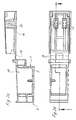
- Fig.1a, 1b
- Schnittdarstellungen einer erfindungsgemäßen Verbindungsklemme in verschiedenen Betriebsstellungen;
- Fig. 2
- verschiedene Darstellungen eines Kunststoff-Spritzgußgehäuses für die Verbindungsklemme aus Fig. 1; und
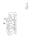
- Fig.3a, 3b
- perspektivische Ansichten einer erfindungsgemäßen Verbindungsklemme mit und ohne in diese eingeführte Leiter;
- Fig. 3c
- eine Ansicht einer Blattklemmfeder für die Verbindungsklemme aus Fig. 1;
- Fig. 4
- eine perspektivische Ansicht einer weiteren erfindungsgemäßen Verbindungsklemme ohne in diese eingeführte Leiter; und
- Fig. 5, 6
- eine perspektivische Ansicht einer nochmals abgewandelten Ausführungsbeispiels einer erfindungsgemäßen Verbindungsklemme mit und ohne in diese eingeführte Leiter.
- Gehäuse
- 2
- Stirnseite
- 4, 6
- Einführöffnungen
- 8a, 8b
- Einführöffnung
- 10
- Prüfabgriffsöffnung
- 12
- Deckelteil
- 14
- Filmscharnier
- 16
- Einführraum
- 18
- Blattklemmfeder
- 20
- Klemmschenkel
- 22, 24
- Metallkontaktrahmen
- 26
- Klemmschenkelabschnitte
- 22a, 22b
- Schlitz
- 28
- Einführschlitze
- 30
- Vorsprünge
- 32a, 32b
- Seitenwände
- 34
- Hintergriffe
- 36
- Hinterschnitte
- 38
- Gehäusebasisteil
- 40
- Seite
- 42
- Vorsprung
- 44
- Leiter
- 46, 48, 50
- Kabel
- 46', 48'
- Anschläge
- 52a, 52b, 52c
- Vorsprünge
- 54a, 54b, 54c
- Randkontur
- 56
- Ausnehmung
- 58
- Anschlagelement
- 60
- Aufnahme
- 62
- Isolierung
- 64
- Fortsatz
- 66
- Einführung
- 68
Claims (13)
- Verbindungsklemme für elektrische Leiter, insbesondere Leuchtenklemme, die folgendes aufweist:dadurch gekennzeichnet, daßeine aus einem federnden Flachmaterial gefertigte Blattklemmfeder mit einem Grundabschnitt und zwei vom Grundabschnitt zueinander hin gebogene Klemmschenkel, welche schräg zur Leitereinführrichtung ausgerichtet sind,einen im Querschnitt U-förmigen Metallkontaktrahmen, in welchen die Blattklemmfeder derart einsetzbar ist, daß zwischen den Klemmschenkeln und einem Schenkel des Metallkontaktrahmens aus einander gegenüberliegenden Richtungen die elektrischen Leiter festklemmbar sind, undein Gehäuse zur Aufnahme des Metallkontaktrahmens nebst der darin eingesetzten Blattklemmfeder,die Blattklemmfeder (20) einseitig derart geschlitzt ausgeführt ist, so daß zumindest von dieser Seite der Blattklemmfeder (20) her zwei Leiter (46, 48) getrennt voneinander in der Blattklemmfeder (20) festklemmbar sind,der Metallkontaktrahmen einen Vorsprung (42) aufweist, welcher die von der geschlitzten Seite der Blattklemmfeder (20) zwischen die Blattklemmfeder (20) und den Metallkontaktrahmen einsetzbaren zwei Leiter (46, 48) beim Einführen der Leiter (46, 48) auseinander führt.
- Verbindungsklemme nach Anspruch 1, dadurch gekennzeichnet, daß das Gehäuse (2) als Spritzgußteil aus Kunststoff ausgeführt ist, welches ein Gehäusebasisteil (28) und einen mit dem Gehäusebasisteil (28) über ein Filmscharnier (16) verbundenen, schwenkbaren Deckelteil (14) aufweist, der am Gehäusebasisteil (28) verrastbar ist.
- Verbindungsklemme nach einem der vorstehenden Ansprüche, dadurch gekennzeichnet, daß das Gehäuse (2) im wesentlichen rechtwinklig ausgebildet ist und an eíner ersten von zwei einander gegenüberliegenden Stirnseiten (4) mit zwei direkt nebeneinander liegenden Einführöffnungen/Bohrungen (8) für die beiden parallelen Leiter (46, 48) und an der dieser Stirnseite (4) gegenüberliegenden Seite (6) mit einer einzigen weiteren Einführöffnung (10) zum Einführen des weiteren Leiters (50) nebst Isolierung versehen ist.
- Verbindungsklemme nach einem der vorstehenden Ansprüche oder nach dem Oberbegriff des Anspruches 1, dadurch gekennzeichnet, daß der Metallkontaktrahmen (26) Einführschlitze (30) für zwei an der Innenseite des Deckelteils (14) nebeneinander liegend ausgebildete Vorsprünge (32a, 32b) aufweist, welche ein Widerlager für die Klemmschenkelabschnitte (24a, 24b) der geschlitzten Klemmschenkels bilden und derart geformt sind, daß sie beim Betätigen des Deckels zwei Klemmschenkel (22, 24) der Blattklemmfeder (20) synchron niederdrücken.
- Verbindungsklemme nach einem der vorstehenden Ansprüche, dadurch gekennzeichnet, daß der Metallkontaktrahmen (26) mit wenigstens einem inneren Anschlag (52a, 52b, 52c) für die in die Verbindungsklemme einführbaren Leiter versehen ist.
- Verbindungsklemme nach einem der vorstehenden Ansprüche, dadurch gekennzeichnet, daß die Anschläge als nach innen gebogene Abschnitte (52a, 52b, 52c) des Metallkontaktrahmens (26) ausgebildet sind.
- Verbindungsklemme nach einem der vorstehenden Ansprüche, dadurch gekennzeichnet, daß der Metallkontaktrahmen (26) mit zu seiner Innenseite gerichteten Vorsprüngen (54a, 54b, 54c) versehen ist, welche als Anlage- und Kontaktbereiche für die zwischen der Blattklemmfeder (20) und dem Metallkontaktrahmen (26) festklemmbaren Leiter (46 - 50) dienen.
- Verbindungsklemme nach einem der vorstehenden Ansprüche, dadurch gekennzeichnet, daß die Blattklemmfeder (20) in ihren Anlagebereichen für die Leiter einer der Leiterform angepaßte Randkontur (56) aufweist.
- Verbindungsklemme nach einem der vorstehenden Ansprüche, dadurch gekennzeichnet, daß an den Stirnseiten des Gehäuses Prüfabgriffsöffnungen (12, 13) ausgebildet sind.
- Verbindungsklemme nach einem der vorstehenden Ansprüche, dadurch gekennzeichnet, daß die Blattklemmfeder (20) mit einer Ausnehmung (58) versehen ist, durch welche ein stiftartiges Anschlagelement (60) in die Blattklemmfeder einschiebbar ist, welches zur Begrenzung der Bewegung des Leiters (50) dient.
- Verbindungsklemme nach einem der vorstehenden Ansprüche, dadurch gekennzeichnet, daß das Anschlagelement (68) als Teil des Gehäuses (2) ausgebildet ist.
- Verbindungsklemme nach einem der vorstehenden Ansprüche oder nach dem Oberbegriff des Anspruches 1, dadurch gekennzeichnet, daß der Fortsatz (66) eine trichterförmige Einführung (68) aufweist.
- Verbindungsklemme nach Anspruch 12, dadurch gekennzeichnet, daß die trichterförmige Einführung (68) asymmetrisch ausgebildet ist.
Applications Claiming Priority (4)
| Application Number | Priority Date | Filing Date | Title |
|---|---|---|---|
| DE20008107 | 2000-05-05 | ||
| DE20008107U | 2000-05-05 | ||
| DE20013439U | 2000-08-04 | ||
| DE20013439U DE20013439U1 (de) | 2000-05-05 | 2000-08-04 | Verbindungsklemme mit Blattklemmfeder |
Publications (3)
| Publication Number | Publication Date |
|---|---|
| EP1152489A2 true EP1152489A2 (de) | 2001-11-07 |
| EP1152489A3 EP1152489A3 (de) | 2002-01-23 |
| EP1152489B1 EP1152489B1 (de) | 2003-01-02 |
Family
ID=26056244
Family Applications (1)
| Application Number | Title | Priority Date | Filing Date |
|---|---|---|---|
| EP01108004A Expired - Lifetime EP1152489B1 (de) | 2000-05-05 | 2001-03-29 | Verbindungsklemme mit Blattklemmfeder |
Country Status (3)
| Country | Link |
|---|---|
| EP (1) | EP1152489B1 (de) |
| AT (1) | ATE230522T1 (de) |
| ES (1) | ES2187488T3 (de) |
Cited By (9)
| Publication number | Priority date | Publication date | Assignee | Title |
|---|---|---|---|---|
| EP1483804A4 (de) * | 2002-03-06 | 2006-08-16 | Ideal Ind | Eindrück-drahtverbinder |
| EP2280453A1 (de) * | 2009-07-31 | 2011-02-02 | Wago Verwaltungsgesellschaft mbH | Steckverbinder |
| CN101079524B (zh) * | 2006-04-21 | 2011-10-26 | 维哥经营公司mbh | 电气连接器的绝缘材料外壳 |
| WO2014094006A1 (de) * | 2012-12-21 | 2014-06-26 | Tridonic Connection Technology Gmbh & Co Kg | Leuchtmittel, insbesondere led-modul |
| CN103326136B (zh) * | 2007-07-09 | 2016-03-02 | 理想工业公司 | 直插推入线连接器 |
| WO2020016395A1 (de) * | 2018-07-19 | 2020-01-23 | Wago Verwaltungsgesellschaft Mbh | Leiteranschlussklemme |
| JP2020035528A (ja) * | 2018-08-27 | 2020-03-05 | オムロン株式会社 | コネクタ式スクリューレス端子台 |
| JP2020035527A (ja) * | 2018-08-27 | 2020-03-05 | オムロン株式会社 | コネクタ用ソケット部品およびコネクタ |
| CN112673526A (zh) * | 2018-09-14 | 2021-04-16 | 威德米勒界面有限公司及两合公司 | 用于电导体的汇流排以及具有所述汇流排的组件 |
Families Citing this family (1)
| Publication number | Priority date | Publication date | Assignee | Title |
|---|---|---|---|---|
| US7491098B1 (en) | 2007-10-10 | 2009-02-17 | General Electric Company | Screwless terminal for electrical leads |
Family Cites Families (4)
| Publication number | Priority date | Publication date | Assignee | Title |
|---|---|---|---|---|
| DE2432084A1 (de) * | 1974-07-04 | 1976-01-22 | Wago Kontakttechnik Gmbh | Schraubenlose anschluss- oder verbindungsklemme fuer elektrische leitungen |
| DE2609291C2 (de) * | 1976-03-06 | 1984-04-12 | Hermann Kleinhuis GmbH & Co KG, 5880 Lüdenscheid | Schraubenlose Anschlußklemme zur Stromübertragung von elektrischen Leitern |
| DE3743410A1 (de) * | 1987-12-21 | 1989-06-29 | Electro Terminal Gmbh | Schraubenlose verbindungsklemme |
| DE4444438A1 (de) * | 1994-12-14 | 1996-06-20 | Kleinhuis Hermann Gmbh | Schraubenlose Klemme |
-
2001
- 2001-03-29 AT AT01108004T patent/ATE230522T1/de active
- 2001-03-29 EP EP01108004A patent/EP1152489B1/de not_active Expired - Lifetime
- 2001-03-29 ES ES01108004T patent/ES2187488T3/es not_active Expired - Lifetime
Cited By (13)
| Publication number | Priority date | Publication date | Assignee | Title |
|---|---|---|---|---|
| EP1483804A4 (de) * | 2002-03-06 | 2006-08-16 | Ideal Ind | Eindrück-drahtverbinder |
| CN101079524B (zh) * | 2006-04-21 | 2011-10-26 | 维哥经营公司mbh | 电气连接器的绝缘材料外壳 |
| CN103326136B (zh) * | 2007-07-09 | 2016-03-02 | 理想工业公司 | 直插推入线连接器 |
| EP2280453A1 (de) * | 2009-07-31 | 2011-02-02 | Wago Verwaltungsgesellschaft mbH | Steckverbinder |
| US7988504B2 (en) | 2009-07-31 | 2011-08-02 | Wago Verwaltungsgesellschaft Mbh | Plug connector |
| US9383067B2 (en) | 2012-12-21 | 2016-07-05 | Tridonic Gmbh & Co Kg | Light-emitting means, in particular LED module |
| WO2014094006A1 (de) * | 2012-12-21 | 2014-06-26 | Tridonic Connection Technology Gmbh & Co Kg | Leuchtmittel, insbesondere led-modul |
| WO2020016395A1 (de) * | 2018-07-19 | 2020-01-23 | Wago Verwaltungsgesellschaft Mbh | Leiteranschlussklemme |
| US11777233B2 (en) | 2018-07-19 | 2023-10-03 | Wago Verwaltungsgesellschaft Mbh | Conductor connection terminal |
| JP2020035528A (ja) * | 2018-08-27 | 2020-03-05 | オムロン株式会社 | コネクタ式スクリューレス端子台 |
| JP2020035527A (ja) * | 2018-08-27 | 2020-03-05 | オムロン株式会社 | コネクタ用ソケット部品およびコネクタ |
| CN112673526A (zh) * | 2018-09-14 | 2021-04-16 | 威德米勒界面有限公司及两合公司 | 用于电导体的汇流排以及具有所述汇流排的组件 |
| CN112673526B (zh) * | 2018-09-14 | 2024-06-11 | 威德米勒界面有限公司及两合公司 | 用于电导体的汇流排以及具有所述汇流排的组件 |
Also Published As
| Publication number | Publication date |
|---|---|
| ATE230522T1 (de) | 2003-01-15 |
| ES2187488T3 (es) | 2003-06-16 |
| EP1152489A3 (de) | 2002-01-23 |
| EP1152489B1 (de) | 2003-01-02 |
Similar Documents
| Publication | Publication Date | Title |
|---|---|---|
| EP3324490B1 (de) | Federklemmkontakt zur kontaktierung elektrischer leiter, leiteranschlussklemme und verfahren zur herstellung eines federklemmkontakts | |
| EP1109269B1 (de) | Elektrischer Anschlusskontakt und Lampenfassung mit einem solchen Kontakt | |
| DE19817927C1 (de) | Steckverbinder als Buchsen- oder Stiftteil und mit einem Federkraftklemmanschluß für elektr. Leiter | |
| EP0899818A2 (de) | Elektrische Anschlussklemme, insbesondere für den Einsatz auf Leiterplatten | |
| EP0959529B1 (de) | Elektrische Anschlussbaueinheit | |
| DE20114612U1 (de) | Reihenklemme mit Schneidkontakten und Anschlußvorrichtung | |
| EP1253670A2 (de) | Federklemme und Federklemmenreihung | |
| DE102011056043B4 (de) | Stromschienenabgriffelement | |
| EP1152489B1 (de) | Verbindungsklemme mit Blattklemmfeder | |
| EP0621661A2 (de) | Fassung für elektrische Betriebsmittel | |
| EP3849018B1 (de) | Leiteranschlussklemme | |
| DE102016102036B4 (de) | Elektrischer Steckkontakt, elektrische Anschlussklemme und Verfahren zur Herstellung eines elektrischen Steckkontakts | |
| EP0676826B1 (de) | Elektrischer Kontakt zum Anschluss von mindestens zwei Leitern | |
| EP0984513B1 (de) | Kontakteinsatz für Industriestecker | |
| EP1523065B1 (de) | Elektrische Klemme | |
| EP1753087A2 (de) | Elektrische Klemme | |
| EP1020954B1 (de) | Elektrische Anschlussklemme | |
| DE19900452A1 (de) | Elektrischer Verbinder mit Verbiegungsverhinderungsstruktur | |
| DE10111571B4 (de) | Elektrisches Kontaktelement und Steckverbinderanordnung mit einem elektrischen Kontaktelement und einem Gehäuse | |
| EP0921611B1 (de) | Netzstromanschlussdose und -schalter | |
| DE20013439U1 (de) | Verbindungsklemme mit Blattklemmfeder | |
| DE19914308A1 (de) | Elektrische Anschlußbaueinheit | |
| DE10034589A1 (de) | Anschlußklemme für elektrische Leiter | |
| DE10006885B4 (de) | Reihenklemme mit trennbarer Kontaktvorrichtung | |
| EP4443656A1 (de) | Kontaktbaugruppe zum anschluss eines elektrischen leiters sowie leiteranschlussklemme mit einer solchen kontaktbaugruppe |
Legal Events
| Date | Code | Title | Description |
|---|---|---|---|
| PUAI | Public reference made under article 153(3) epc to a published international application that has entered the european phase |
Free format text: ORIGINAL CODE: 0009012 |
|
| AK | Designated contracting states |
Kind code of ref document: A2 Designated state(s): AT BE CH CY DE DK ES FI FR GB GR IE IT LI LU MC NL PT SE TR |
|
| AX | Request for extension of the european patent |
Free format text: AL;LT;LV;MK;RO;SI |
|
| PUAL | Search report despatched |
Free format text: ORIGINAL CODE: 0009013 |
|
| AK | Designated contracting states |
Kind code of ref document: A3 Designated state(s): AT BE CH CY DE DK ES FI FR GB GR IE IT LI LU MC NL PT SE TR |
|
| AX | Request for extension of the european patent |
Free format text: AL;LT;LV;MK;RO;SI |
|
| 17P | Request for examination filed |
Effective date: 20011229 |
|
| 17Q | First examination report despatched |
Effective date: 20020320 |
|
| GRAH | Despatch of communication of intention to grant a patent |
Free format text: ORIGINAL CODE: EPIDOS IGRA |
|
| GRAH | Despatch of communication of intention to grant a patent |
Free format text: ORIGINAL CODE: EPIDOS IGRA |
|
| AKX | Designation fees paid |
Free format text: AT BE CH CY DE DK ES FI FR GB GR IE IT LI LU MC NL PT SE TR |
|
| GRAH | Despatch of communication of intention to grant a patent |
Free format text: ORIGINAL CODE: EPIDOS IGRA |
|
| GRAA | (expected) grant |
Free format text: ORIGINAL CODE: 0009210 |
|
| AK | Designated contracting states |
Kind code of ref document: B1 Designated state(s): AT BE CH CY DE DK ES FI FR GB GR IE IT LI LU MC NL PT SE TR |
|
| PG25 | Lapsed in a contracting state [announced via postgrant information from national office to epo] |
Ref country code: IT Free format text: LAPSE BECAUSE OF FAILURE TO SUBMIT A TRANSLATION OF THE DESCRIPTION OR TO PAY THE FEE WITHIN THE PRESCRIBED TIME-LIMIT;WARNING: LAPSES OF ITALIAN PATENTS WITH EFFECTIVE DATE BEFORE 2007 MAY HAVE OCCURRED AT ANY TIME BEFORE 2007. THE CORRECT EFFECTIVE DATE MAY BE DIFFERENT FROM THE ONE RECORDED. Effective date: 20030102 Ref country code: IE Free format text: LAPSE BECAUSE OF FAILURE TO SUBMIT A TRANSLATION OF THE DESCRIPTION OR TO PAY THE FEE WITHIN THE PRESCRIBED TIME-LIMIT Effective date: 20030102 Ref country code: GR Free format text: LAPSE BECAUSE OF FAILURE TO SUBMIT A TRANSLATION OF THE DESCRIPTION OR TO PAY THE FEE WITHIN THE PRESCRIBED TIME-LIMIT Effective date: 20030102 Ref country code: TR Free format text: LAPSE BECAUSE OF FAILURE TO SUBMIT A TRANSLATION OF THE DESCRIPTION OR TO PAY THE FEE WITHIN THE PRESCRIBED TIME-LIMIT Effective date: 20030102 Ref country code: FI Free format text: LAPSE BECAUSE OF FAILURE TO SUBMIT A TRANSLATION OF THE DESCRIPTION OR TO PAY THE FEE WITHIN THE PRESCRIBED TIME-LIMIT Effective date: 20030102 Ref country code: GB Free format text: LAPSE BECAUSE OF FAILURE TO SUBMIT A TRANSLATION OF THE DESCRIPTION OR TO PAY THE FEE WITHIN THE PRESCRIBED TIME-LIMIT Effective date: 20030102 |
|
| REF | Corresponds to: |
Ref document number: 230522 Country of ref document: AT Date of ref document: 20030115 Kind code of ref document: T |
|
| REG | Reference to a national code |
Ref country code: GB Ref legal event code: FG4D Free format text: 20030102:NOT ENGLISH |
|
| REG | Reference to a national code |
Ref country code: CH Ref legal event code: EP |
|
| REG | Reference to a national code |
Ref country code: IE Ref legal event code: FG4D Free format text: GERMAN |
|
| REF | Corresponds to: |
Ref document number: 50100074 Country of ref document: DE Date of ref document: 20030206 Kind code of ref document: P |
|
| REG | Reference to a national code |
Ref country code: CH Ref legal event code: NV Representative=s name: ISLER & PEDRAZZINI AG |
|
| PG25 | Lapsed in a contracting state [announced via postgrant information from national office to epo] |
Ref country code: CY Free format text: LAPSE BECAUSE OF FAILURE TO SUBMIT A TRANSLATION OF THE DESCRIPTION OR TO PAY THE FEE WITHIN THE PRESCRIBED TIME-LIMIT Effective date: 20030329 Ref country code: LU Free format text: LAPSE BECAUSE OF NON-PAYMENT OF DUE FEES Effective date: 20030329 |
|
| PG25 | Lapsed in a contracting state [announced via postgrant information from national office to epo] |
Ref country code: MC Free format text: LAPSE BECAUSE OF NON-PAYMENT OF DUE FEES Effective date: 20030331 |
|
| PG25 | Lapsed in a contracting state [announced via postgrant information from national office to epo] |
Ref country code: SE Free format text: LAPSE BECAUSE OF FAILURE TO SUBMIT A TRANSLATION OF THE DESCRIPTION OR TO PAY THE FEE WITHIN THE PRESCRIBED TIME-LIMIT Effective date: 20030402 Ref country code: DK Free format text: LAPSE BECAUSE OF FAILURE TO SUBMIT A TRANSLATION OF THE DESCRIPTION OR TO PAY THE FEE WITHIN THE PRESCRIBED TIME-LIMIT Effective date: 20030402 Ref country code: PT Free format text: LAPSE BECAUSE OF FAILURE TO SUBMIT A TRANSLATION OF THE DESCRIPTION OR TO PAY THE FEE WITHIN THE PRESCRIBED TIME-LIMIT Effective date: 20030402 |
|
| REG | Reference to a national code |
Ref country code: ES Ref legal event code: FG2A Ref document number: 2187488 Country of ref document: ES Kind code of ref document: T3 |
|
| GBV | Gb: ep patent (uk) treated as always having been void in accordance with gb section 77(7)/1977 [no translation filed] |
Effective date: 20030102 |
|
| REG | Reference to a national code |
Ref country code: IE Ref legal event code: FD4D Ref document number: 1152489E Country of ref document: IE |
|
| ET | Fr: translation filed | ||
| PLBE | No opposition filed within time limit |
Free format text: ORIGINAL CODE: 0009261 |
|
| STAA | Information on the status of an ep patent application or granted ep patent |
Free format text: STATUS: NO OPPOSITION FILED WITHIN TIME LIMIT |
|
| 26N | No opposition filed |
Effective date: 20031003 |
|
| REG | Reference to a national code |
Ref country code: CH Ref legal event code: PCAR Free format text: ISLER & PEDRAZZINI AG;POSTFACH 1772;8027 ZUERICH (CH) |
|
| PGFP | Annual fee paid to national office [announced via postgrant information from national office to epo] |
Ref country code: NL Payment date: 20110316 Year of fee payment: 11 Ref country code: AT Payment date: 20110314 Year of fee payment: 11 Ref country code: FR Payment date: 20110404 Year of fee payment: 11 Ref country code: CH Payment date: 20110324 Year of fee payment: 11 |
|
| PGFP | Annual fee paid to national office [announced via postgrant information from national office to epo] |
Ref country code: DE Payment date: 20110325 Year of fee payment: 11 Ref country code: BE Payment date: 20110311 Year of fee payment: 11 Ref country code: ES Payment date: 20110325 Year of fee payment: 11 |
|
| BERE | Be: lapsed |
Owner name: *WEIDMULLER INTERFACE G.M.B.H. & CO. Effective date: 20120331 |
|
| REG | Reference to a national code |
Ref country code: NL Ref legal event code: V1 Effective date: 20121001 |
|
| REG | Reference to a national code |
Ref country code: CH Ref legal event code: PL |
|
| REG | Reference to a national code |
Ref country code: AT Ref legal event code: MM01 Ref document number: 230522 Country of ref document: AT Kind code of ref document: T Effective date: 20120329 |
|
| REG | Reference to a national code |
Ref country code: FR Ref legal event code: ST Effective date: 20121130 |
|
| REG | Reference to a national code |
Ref country code: DE Ref legal event code: R119 Ref document number: 50100074 Country of ref document: DE Effective date: 20121002 |
|
| PG25 | Lapsed in a contracting state [announced via postgrant information from national office to epo] |
Ref country code: BE Free format text: LAPSE BECAUSE OF NON-PAYMENT OF DUE FEES Effective date: 20120331 Ref country code: AT Free format text: LAPSE BECAUSE OF NON-PAYMENT OF DUE FEES Effective date: 20120329 Ref country code: CH Free format text: LAPSE BECAUSE OF NON-PAYMENT OF DUE FEES Effective date: 20120331 Ref country code: FR Free format text: LAPSE BECAUSE OF NON-PAYMENT OF DUE FEES Effective date: 20120402 Ref country code: LI Free format text: LAPSE BECAUSE OF NON-PAYMENT OF DUE FEES Effective date: 20120331 |
|
| PG25 | Lapsed in a contracting state [announced via postgrant information from national office to epo] |
Ref country code: NL Free format text: LAPSE BECAUSE OF NON-PAYMENT OF DUE FEES Effective date: 20121001 |
|
| REG | Reference to a national code |
Ref country code: ES Ref legal event code: FD2A Effective date: 20130710 |
|
| PG25 | Lapsed in a contracting state [announced via postgrant information from national office to epo] |
Ref country code: ES Free format text: LAPSE BECAUSE OF NON-PAYMENT OF DUE FEES Effective date: 20120330 |
|
| PG25 | Lapsed in a contracting state [announced via postgrant information from national office to epo] |
Ref country code: DE Free format text: LAPSE BECAUSE OF NON-PAYMENT OF DUE FEES Effective date: 20121002 |