EP1152175A1 - Flachdichtung - Google Patents
Flachdichtung Download PDFInfo
- Publication number
- EP1152175A1 EP1152175A1 EP00109677A EP00109677A EP1152175A1 EP 1152175 A1 EP1152175 A1 EP 1152175A1 EP 00109677 A EP00109677 A EP 00109677A EP 00109677 A EP00109677 A EP 00109677A EP 1152175 A1 EP1152175 A1 EP 1152175A1
- Authority
- EP
- European Patent Office
- Prior art keywords
- positioning
- clamping
- flat gasket
- channel
- positioning channel
- Prior art date
- Legal status (The legal status is an assumption and is not a legal conclusion. Google has not performed a legal analysis and makes no representation as to the accuracy of the status listed.)
- Granted
Links
- 238000003780 insertion Methods 0.000 claims description 16
- 230000037431 insertion Effects 0.000 claims description 16
- 238000006073 displacement reaction Methods 0.000 claims description 14
- 239000007769 metal material Substances 0.000 claims description 4
- 230000000694 effects Effects 0.000 description 6
- 210000001331 nose Anatomy 0.000 description 5
- 239000000463 material Substances 0.000 description 4
- 238000007688 edging Methods 0.000 description 2
- 238000004519 manufacturing process Methods 0.000 description 2
- 238000000034 method Methods 0.000 description 2
- 238000004080 punching Methods 0.000 description 2
- 102000010637 Aquaporins Human genes 0.000 description 1
- 229910000831 Steel Inorganic materials 0.000 description 1
- 210000001217 buttock Anatomy 0.000 description 1
- 238000002485 combustion reaction Methods 0.000 description 1
- 238000010276 construction Methods 0.000 description 1
- 230000007547 defect Effects 0.000 description 1
- 230000002349 favourable effect Effects 0.000 description 1
- 210000003128 head Anatomy 0.000 description 1
- 239000010959 steel Substances 0.000 description 1
Images











Classifications
-
- F—MECHANICAL ENGINEERING; LIGHTING; HEATING; WEAPONS; BLASTING
- F16—ENGINEERING ELEMENTS AND UNITS; GENERAL MEASURES FOR PRODUCING AND MAINTAINING EFFECTIVE FUNCTIONING OF MACHINES OR INSTALLATIONS; THERMAL INSULATION IN GENERAL
- F16J—PISTONS; CYLINDERS; SEALINGS
- F16J15/00—Sealings
- F16J15/02—Sealings between relatively-stationary surfaces
- F16J15/06—Sealings between relatively-stationary surfaces with solid packing compressed between sealing surfaces
- F16J15/08—Sealings between relatively-stationary surfaces with solid packing compressed between sealing surfaces with exclusively metal packing
- F16J15/0818—Flat gaskets
- F16J15/0825—Flat gaskets laminated
- F16J15/0831—Flat gaskets laminated with mounting aids
-
- F—MECHANICAL ENGINEERING; LIGHTING; HEATING; WEAPONS; BLASTING
- F16—ENGINEERING ELEMENTS AND UNITS; GENERAL MEASURES FOR PRODUCING AND MAINTAINING EFFECTIVE FUNCTIONING OF MACHINES OR INSTALLATIONS; THERMAL INSULATION IN GENERAL
- F16J—PISTONS; CYLINDERS; SEALINGS
- F16J15/00—Sealings
- F16J15/02—Sealings between relatively-stationary surfaces
- F16J15/06—Sealings between relatively-stationary surfaces with solid packing compressed between sealing surfaces
- F16J15/08—Sealings between relatively-stationary surfaces with solid packing compressed between sealing surfaces with exclusively metal packing
- F16J15/0818—Flat gaskets
- F16J2015/085—Flat gaskets without fold over
Definitions
- the present invention relates to a flat gasket for arrangement between two components of a motor vehicle, in particular between an engine block and a cylinder head, which comprises one or more layers, being capable of or the layers of the flat gasket each have at least one positioning channel through hole is formed and these positioning channel through holes at least one positioning channel for Inclusion of a positioning element arranged on one of the components form and wherein at least one layer of the flat gasket is designed as a clamping position in which a clamping element is arranged with at least one clamping area which before inserting the positioning element into the positioning channel is located at least partially in the positioning channel and after inserting the positioning element into the positioning channel so in clamping contact with the positioning element stands that the flat seal by clamping action on the positioning element is held.
- Such flat seals are for example from the EP 0 500 274 A1 or EP 0 500 282 A1.
- Flat seals each comprise at least two layers, where one layer serves as a clamping position and a sheet and at least a flap-shaped, integral with the sheet Clamping element includes which when inserting the positioning element into the positioning channel from the clamping position is deformed into a recess, which in another layer of the flat gasket adjacent to the clamping position is trained.
- the present invention is therefore based on the object to create a flat gasket of the type mentioned at the outset, which is more versatile and usable than the known ones Gaskets.
- This task is done with a flat gasket with the features of the preamble of claim 1 solved according to the invention in that that the clamping position of the flat gasket has a recess Includes the clamping element and that the clamping element when inserting the positioning element into the positioning channel at least partially along a direction of displacement, which is directed essentially parallel to the clamping position, is moved into the recess within the clamping position.
- positioning channel is that area to understand the flat gasket, which after insertion of the positioning element completely from the positioning element is filled out.
- the positioning element is perpendicular to the positions of the flat gasket inserted in the positioning channel, so is the direction of displacement of the clamping element substantially perpendicular directed to the axis of the positioning channel.
- Different areas of the clamping element can along different directions of displacement, however all directed substantially parallel to the clamping position are moved.
- different Areas of the clamping element along different Displacement directions which are radial to the axis of the Positioning channel are directed to be moved.
- the concept of the invention has the advantage that the The clamping function is guaranteed solely by the design of the clamping position is without this adjoining the clamping position Lay the flat gasket in a specially adapted manner should be designed.
- the Flat gasket according to the invention only the clamping position and none another layer, since the clamping element does not include the clamping position leaves.
- the clamping element is completely shifted within the clamping position , it is also not necessary in the to the Seal adjacent components of the motor vehicle, for example in the engine block or in the cylinder head, recesses or chamfers to accommodate the clamping element.
- the clamping position of the invention ensures Flat seal the desired clamping effect regardless in what orientation the flat gasket on the positioning element is pushed open.
- the clamping element of the flat gasket according to the invention be designed so that after removing the Positioning element from the positioning channel in its original Position moved back, so that the invention Flat gasket several times on a positioning element can be pressed without the clamping force in considerable Diminishes.
- the flat seal in addition to the Clamping position comprises at least one positioning position, the Positioning channel through hole belonging to positioning channel formed as a positioning hole for the positioning element which is essentially the same cross section as that Has positioning element.
- the flat gasket has at least two positioning positions includes.
- the flat gasket has at least two clamping positions includes.
- the invention is particularly easy to manufacture Flat seal if it is advantageously provided that the clamping layer comprises a plate made of a metallic material and that the clamping element in one piece with this plate is trained.
- Such a clamping position can be achieved in particular by a simple one Punching process.
- the clamping element as a web is formed, which belongs to the positioning channel Positioning channel through hole of the clamping position and that in the Recess provided in the clamping position for receiving the clamping element separates from each other. Because such a clamping element on his both ends firmly connected to the plate of the clamping position there is only a slight risk that the clamping element break off and the desired clamping effect is lost could. In addition, a trained in this way Clamping element have a high restoring force, so that a Return to the starting position after removing the positioning element guaranteed from the positioning channel.
- the clamping position a plate made of a metallic material and that the clamping element is designed as a separate part. This allows one of the material of the clamping element Select different material, which for example has a higher elasticity and thus a Return of the clamping element to the starting position after removal of the positioning element from the positioning channel.
- Such a separate clamping element can be used, for example, as annular spring element may be formed.
- such a separate clamping element can be used as on at least one end by means of a bracket on the Plate held spring element may be formed.
- the clamping element is such Has elasticity that after removing the positioning element from the positioning channel at least partially moved back into the positioning channel, so that an adequate Clamping effect even if the Flat seal on a positioning element is guaranteed, without the clamping element acting from outside in the Original state must be reset.
- the clamping element at least two from each other has spaced clamping areas.
- the flat gasket according to the invention is particularly suitable for use with a component of a motor vehicle, in particular an engine block or cylinder head, which at least a positioning element arranged thereon and a held by clamping action on the positioning element according to the invention
- Flat gasket includes.
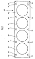
- FIGS. 1 to 5 designated as a whole by 100 Flat gasket includes, as best seen in FIG. 3 can be seen, three layers arranged one above the other, namely a lower positioning layer 102a, an upper positioning layer 102b and one arranged between the two positioning layers Clamp position 104.
- Each of the layers 102a, 102b, 104 essentially comprises one rectangular plate 106 or 108 made of sheet steel which by punching through openings described in more detail below are trained.
- the thicknesses of the plates 106 of the positioning layers on the one hand and the plate 108 of the clamping position, on the other hand, can be one another be chosen the same or different from each other; preferably the thickness of the plate 108 of the clamping layer 104 increases selected as the thickness of the plates 106 of the positioning layers 102a, 102b.
- the materials of the plates 106 and 108 can be one another be the same or different from each other.
- a material is selected for the plate 108 of the clamping layer 104, which has a high elasticity.
- the positioning positions are 102a, 102b and the clamping layer 104 by means of the four corner areas of the flat gasket 100 arranged rivets 110 firmly connected so that the positioning positions 102a, 102b cannot be released from the clamping position 104.
- the flat seal 100 shown in FIGS. 1 to 5 is intended serve as a cylinder head gasket and is therefore equipped with several for example, four, combustion chamber openings 112 provided by in the clamping position 104 and the positioning positions 102a, 102b provided through holes aligned with each other are formed.
- the flat seal 100 comprises purely schematically shown Through channels 114, which are also out in the Clamping layer 104 and the positioning layers 102a, 102b provided Through holes that are aligned with each other are formed are and in a known manner as oil channels, water channels or for the connection of bolts, which connect the engine block and the cylinder head of an engine in which the flat gasket 100 is used as a cylinder head gasket.
- the flat seal 100 comprises two positioning channels 116, each of which is near a corner region of the flat gasket 100 are arranged and their structure described in more detail below will be.
- the positioning channel through holes 118a, 118b in the positioning positions 102a, 102b are designed as positioning holes 122, that is, these through holes are substantially the same the cross section of a fixed on the engine block 124 Positioning element 126 (see FIGS. 4 and 5), which at the assembly of the flat gasket 100 on the engine block 124 in the each assigned positioning channel 116 is introduced.
- the positioning element 126 formed as a cylindrical positioning pin, which is provided with a chamfer on its front side in order to Insert the positioning pin in the respective positioning channel 116 to facilitate.
- the positioning holes 122 in the positioning layers 102a, 102b is essentially circular, the The diameter of the positioning holes 122 is substantially the same is the same as the diameter of the positioning element 126.
- the diameter of the positioning holes 122 slightly larger than the diameter of the positioning element 126 can be selected. It can also be provided that the positioning holes 122 slightly from the circular shape deviate and have, for example, a slightly elliptical shape.
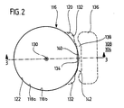
- the positioning channel through hole gives way 120 from the circular shape of the positioning holes 122 in that the positioning channel through hole 120 has two bulges 132, which with respect on the central axis 130 of the positioning channel 116 in are arranged at an angular distance of approximately 90 ° and with one another through a rectilinear section of the boundary of the Positioning channel through hole 120, which as a clamping edge 134 serves, are connected.
- Fig. 2 is next to the positioning channel through hole 120 in the clamping position 104 one-likewise shown in broken lines - recess 136 formed, which also has a through hole in the Clamp position 104 represents.
- the boundary facing the positioning channel through hole 120 The recess 136 follows the boundary of the positioning channel through hole 120 in a substantially constant Distance so that the recess 136 from the positioning channel through hole 120 by a web 138 of essentially constant width is separated.
- FIG. 2 stands by the straight line Clamping edge 134 limited area of the web 138 over the Edges of the positioning holes 122 in the positioning positions 102a, 102b out into the positioning channel 116 as long as the positioning element 126 is not yet in the positioning channel 116 has been introduced.
- This into the positioning channel 116 projecting area of the web 138 is hereinafter referred to as Clamping area 140, the web 138 as a whole as a clamping element 142 be designated.
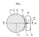
- each positioning element arrives 126 with its chamfered tip ahead through the positioning hole 122 in the lower positioning layer 102a into the positioning channel through hole 120 of the clamping position 104, where it is Clamping element 142 along a radial, that is, perpendicular to the central axis 130 of the positioning channel 116, and parallel to the clamping position 104 extending displacement direction 143 in the Recess 136 displaced into it.
- the clamping element 142 deforms in particular in the Clamping area 140 so that the clamping edge 134 extends to the circumference of the positioning element 126.
- the deformation of the clamping element 142 takes place at least partially elastic, so that the clamping area 140 by an elastic Restoring force of the clamping element 142 against the lateral surface of the positioning element 126 is pressed and so in Clamping contact with the positioning element 126 means that Clamping element 142, which is integral with the clamping element 142 trained plate 108 of the clamping position 104 and the Rivets 110 positioning positions connected to the clamping position 104 102a, 102b of the flat seal 100 by clamping action on the Positioning element 126 are held.
- the positioning element penetrates 126 after the flat gasket has been fully pressed on 100 also the positioning hole 122 in the upper positioning position 102b.
- the edges of the positioning holes 122 in the positioning positions 102a, 102b lie at least in sections on the lateral surface of the respective positioning element 126 and ensure thus precise positioning and alignment the flat gasket 100 on the engine block 124 relative to the Positioning elements 126.
- the Positioning elements 126 on the engine block 124 and is set the flat gasket 100 is first mounted on the engine block 124.
- the positioning elements 126 are instead fixed on the cylinder head and the flat gasket 100 is first connected to the cylinder head is placed on the engine block 124 before the cylinder head and screwed to it.
- the flat gasket 100 is in relation to the middle one Clamping layer 104 constructed symmetrically, so that they both with the lower positioning layer 102a as well as with the upper one Positioning layer 102b ahead on the positioning elements 126 can be pressed on.
- the positioning layers 102a, 102b are the respective positioning elements 126 grips with a precise fit, remains Evasive movement of the clamping element 142 to the level of Clamp position 104 limited; the clamping element 142 is thus only through the positioning element 126 into the recess 136 moved in without deforming so that a Part of the same in an adjacent position of the flat gasket 100 got into it.
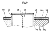
- a second embodiment shown in FIGS. 6 to 9 a flat gasket 100 differs from that above described first embodiment in that the functions the middle layer and the outer layers of the flat gasket 100 are interchanged.
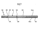
- the second embodiment a flat gasket 100 thus has a lower one Clamping layer 104a and an upper clamping layer 104b and one between the positioning layer 102 arranged in the clamping positions.
- the middle clamping layer 102 has a positioning hole 122, which is essentially the same cross section as the associated one Has positioning element 126.
- the central axis 130 of the positioning channel 116 runs through the center 128 of the Positioning hole 122 of the middle clamping layer 102 perpendicular to the positions of the flat gasket 100.
- the clamping layers 104a and 104b each have positioning channel through holes 120, which by forming two bulges 132 and one that connects them together Clamping edges 134 deviate from the circular shape of the positioning hole 122.
- each of the positioning channel through holes 120 of FIG Clamping layers 104a, 104b are each essentially oval, recess formed as a through hole in the respective position 136 arranged by a as a clamping element 142 serving land 138 from the positioning channel through hole 120 is separated.
- a clamping area 140 of the clamping area delimited by the clamping edge 134 Clamping element 142 stands before the insertion of the respective positioning element 126 on the edge of the positioning hole 122 in the positioning position 102 into the positioning channel 116 before.
- the Clamping areas 140 of the clamping elements 142 are after insertion of the respective positioning element 126 in clamping contact with the positioning element so that the flat seal 100 held on the positioning elements 126 by clamping action is.
- one flat gasket 100 differs from the second Embodiment in that the clamping elements 142nd serving webs 138 of the clamping layers 104a, 104b are not essentially are straight, but curved and each a middle one from the positioning channel through hole 120 curved away into the adjacent recess 136 Include middle section 144, which is opposite opposite curved side portions 146 in the substantially rectilinear end sections 148 of the respective web 138 merges, at which the respective web 138 with the respective Plate 106 of the clamping layer 104a, 104b is connected.
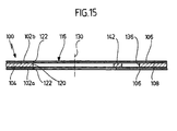
- a fourth embodiment shown in FIGS. 14 to 17 a flat gasket differs from that above described first embodiment in that the in the middle clamping position 104 provided clamping element 142 not as a web fixed to the plate 108 on both sides, but formed as a tongue 150 fixed only on one side is.
- the tongue 150 has a widened end portion 152 which through to the positioning channel through hole 120 borders a substantially straight clamping edge 134 is.
- the clamping edge 134 delimits a clamping area 140 which as Clamping element 142 serving tongue 150, which before insertion of the respective positioning element 126 in the positioning channel 116 on the edge of the positioning holes 122 in the positioning layers 102a, 102b into the positioning channel 116 stands out.
- the positioning channel has through hole 120 only one, adjacent to the tongue 150, Bulge 132 on; instead of the second bulge in this embodiment, the positioning channel through hole 120 passage connecting the recess 136 154 available.
- the positioning channel 116 becomes the tongue 150 perpendicular to the central axis 130 of the positioning channel 116 within the clamping position 104 along a direction of displacement parallel to the clamping position 104 143 moved into the recess 136.
- the clamping area is inserted when the positioning element 126 is inserted 140 of the tongue 150 serving as the clamping element 142 in clamping contact with the outer surface of the positioning element 126, so that the flat seal 100 by clamping action on the positioning element 126 is held.
- the tongue 150 fixed only on one side to the plate 106 has a greater mobility than the web 138 of the first Embodiment, so that the clamping element 142 of the fourth Embodiment more easily displaceable from the positioning channel 116 is.
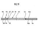
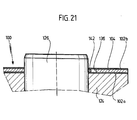
- a fifth embodiment shown in FIGS. 18 to 21 a flat gasket differs from that above described first embodiment in that the in the middle clamping position 104 provided clamping element 142 not as a web fixed to the plate 108 on both sides, but is designed as a separate spring clip 156, which held at both ends in a holder on plate 108 is.
- the boundary of the positioning channel through hole runs 120 of the clamping position 104 in two rounded lugs 158, the ends of which with respect to the central axis 130 of the positioning channel 116 an angular distance of approximately 60 °.
- edges of the receptacle for receiving the clamping element 142 serving recess 136 in the clamping position 104 runs on both sides in each case a nose 160, which each one of the Noses 158 opposite, so that between two noses 158, 160 a passage 162 is formed, which in a drop-shaped Bulge 164 opens out.
- the clamping element 142 in the form of a spring clip 156 which is designed as an essentially cylindrical rod, is with one of its two ends through a passage 162 led into the corresponding bulge 164, the diameter of the spring clip 156 is essentially that Width of the passage 162 corresponds, so that the spring clip 156 is clamped between the two lugs 158 and 160 and a nose 158 together with an opposite one Nose 160 a holder 166 for each Form end of spring clip 156.
- a central clamping area 140 of the serving as clamping element 142 Spring clip 156 stands before the insertion of the respective Positioning element 126 in the positioning channel 116 via the Edging of the positioning holes 122 in the positioning positions 102a, 102b into the positioning channel 116.
- the spring clip 156 has a formality, so that the deflection of the spring clip 156 after removal of the positioning element 126 from the positioning channel 116 is undone and the clamping element 142 after removal the flat gasket 100 from the engine block 124, for example after finding a defect, back in the original Shape available for another clamping process stands.
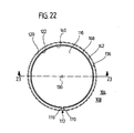
- a sixth embodiment shown in FIGS. 22 to 25 a flat gasket differs from that above fifth embodiment described in that the separate clamping element provided in the middle clamping position 104 142 not as one at each of its two ends Bracket 166 held spring clip 156, rather than an open one Spring ring 168 is formed, which axis 130 surrounding the positioning channel 116 in the clamping position 104, the spring ring 168 being substantially circular Has cross-section and between the two end faces 170 of the spring ring 168, a gap 172 is formed.
- the radially inner region of the spring ring 168 represents one Clamping area 140 of the spring ring serving as clamping element 142 168, which is before the insertion of the respective positioning element 126 into the positioning channel 116 via the Edging of the positioning holes 122 in the positioning positions 102a, 102b protrudes into the positioning channel 116.
- the recess 136 for receiving the clamping element 142 after Introducing the positioning member 126 is at the sixth Embodiment of a flat gasket 100 as the positioning channel 116 concentrically surrounding in the clamping position 104 annular recess formed.
- this embodiment thus includes the positioning channel through hole formed in the clamping position 104 120 a central area whose Cross section the cross section of the positioning element 126 corresponds, and an adjoining annular edge region, which as a recess 136 for receiving the clamping element 142 serves.
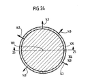
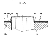
- the spring ring 168 When the respective positioning element 126 is inserted into the Positioning channel 116, the spring ring 168 is expanded and thus radially to the central axis 130 of the positioning channel 116 aligned displacement directions extending within the clamping position 104 143 moved into the recess 136.
- the spring ring 168 has a high degree of formula elasticity so that the spring ring 168 after removing the positioning element 126 from the positioning channel 116 essentially unchanged returns to its original shape.
- the Flat gasket 100 according to the sixth embodiment can therefore easily pressed several times onto positioning elements 126 and are clamped to the same without this the spring rings 168 serving as clamping elements 142 are replaced or reshaped to its original shape should be.
Landscapes
- Engineering & Computer Science (AREA)
- General Engineering & Computer Science (AREA)
- Mechanical Engineering (AREA)
- Gasket Seals (AREA)
Abstract
Description
- Fig. 1
- eine Draufsicht auf eine erfindungsgemäße Flach dichtung;
- Fig. 2
- eine Draufsicht auf einen Positionierkanal einer ersten Ausführungsform einer Flachdichtung, die eine Klemmlage zwischen zwei Positionierlagen und ein als Steg ausgebildetes Klemmelement aufweist, vor dem Einführen des Positionierelements;
- Fig. 3
- einen schematischen Schnitt durch die Flachdich tung aus Fig. 2 längs der Linie 3-3;
- Fig. 4
- eine teilweise geschnittene Draufsicht auf die Flachdichtung aus Fig. 2 nach dem Einführen des Positionierelements;
- Fig. 5
- einen schematischen Schnitt durch die Flachdich tung und das Positionierelement aus Fig. 4 längs der Linie 5-5;
- Fig. 6
- eine Draufsicht auf den Positionierkanal einer zweiten Ausführungsform einer Flachdichtung, wel che eine Positionierlage zwischen zwei Klemmlagen und als Steg mit jeweils einem Klemmbereich aus gebildete Klemmelemente aufweist, vor dem Einfüh ren des Positionierelements;
- Fig. 7
- einen schematischen Schnitt durch die Flachdich tung aus Fig. 6 längs der Linie 7-7;
- Fig. 8
- eine teilweise geschnittene Draufsicht auf die Flachdichtung aus Fig. 6 nach dem Einführen des Positionierelements;
- Fig. 9
- einen schematischen Schnitt durch die Flachdich tung und das Positionierelement aus Fig. 8 längs der Linie 9-9;
- Fig. 10
- eine Draufsicht auf den Positionierkanal einer dritten Ausführungsform einer Flachdichtung, wel che eine Positionierlage zwischen zwei Klemmlagen und als Steg mit jeweils zwei Klemmbereichen aus gebildete Klemmelemente aufweist, vor dem Einfüh ren des Positionierelements;
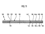
- Fig. 11
- einen schematischen Schnitt durch die Flachdich tung aus Fig. 10 längs der Linie 11-11;
- Fig. 12
- eine teilweise geschnittene Draufsicht auf die Flachdichtung aus Fig. 10 nach dem Einführen des Positionierelements;
- Fig. 13
- einen schematischen Schnitt durch die Flachdich tung und das Positionierelement aus Fig. 12 längs der Linie 13-13;
- Fig. 14
- eine Draufsicht auf den Positionierkanal einer vierten Ausführungsform einer Flachdichtung, wel che eine Klemmlage zwischen zwei Positionierlagen und ein als Zunge ausgebildetes Klemmelement auf weist, vor dem Einführen des Positionierelements;
- Fig. 15
- einen schematischen Schnitt durch die Flachdich tung aus Fig. 14 längs der Linie 15-15;
- Fig. 16
- eine teilweise geschnittene Draufsicht auf die Flachdichtung aus Fig. 14 nach dem Einführen des Positionierelements;
- Fig. 17
- einen schematischen Schnitt durch die Flachdich tung und das Positionierelement aus Fig. 16 längs der Linie 17-17;
- Fig. 18
- eine Draufsicht auf den Positionierkanal einer fünften Ausführungsform einer Flachdichtung, wel che eine Klemmlage zwischen zwei Positionierlagen und ein als Federspange ausgebildetes separates Klemmelement aufweist, vor dem Einführen des Po sitionierelements;
- Fig. 19
- einen schematischen Schnitt durch die Flachdich tung aus Fig. 18 längs der Linie 19-19;
- Fig. 20
- eine teilweise geschnittene Draufsicht auf die Flachdichtung aus Fig. 18 nach dem Einführen des Positionierelements;
- Fig. 21
- einen schematischen Schnitt durch die Flachdich tung und das Positionierelement aus Fig. 20 längs der Linie 21-21;
- Fig. 22
- eine Draufsicht auf den Positionierkanal einer sechsten Ausführungsform einer Flachdichtung, welche eine Klemmlage zwischen zwei Positionier lagen und ein als Federring ausgebildetes separa tes Klemmelement aufweist, vor dem Einführen des Positionierelements;
- Fig. 23
- einen schematischen Schnitt durch die Flachdich tung aus Fig. 22 längs der Linie 23-23;
- Fig. 24
- eine teilweise geschnittene Draufsicht auf die Flachdichtung aus Fig. 22 nach dem Einführen des Positionierelements; und
- Fig. 25
- einen schematischen Schnitt durch die Flachdich tung und das Positionierelement aus Fig. 24 längs der Linie 25-25.
Claims (12)
- Flachdichtung zur Anordnung zwischen zwei Komponenten eines Kraftfahrzeugs, insbesondere zwischen einem Motorblock (124) und einem Zylinderkopf, umfassend eine oder mehrere Lagen, wobei in der Lage oder den Lagen der Flachdichtung (100) jeweils mindestens ein Positionierkanal-Durchgangsloch (118, 120) gebildet ist und diese Positionierkanal-Durchgangslöcher mindestens einen Positionierkanal (116) zur Aufnahme eines an einer der Komponenten angeordneten Positionierelements (126) bilden und wobei mindestens eine Lage der Flachdichtung (100) als Klemmlage (104; 104a, 104b) ausgebildet ist, in welcher ein Klemmelement (142) mit mindestens einem Klemmbereich (140) angeordnet ist, der sich vor Einführen des Positionierelements (126) in den Positionierkanal (116) zumindest teilweise in dem Positionierkanal (116) befindet und nach Einführen des Positionierelements (126) in den Positionierkanal (116) so in Klemmkontakt mit dem Positionierelement (126) steht, daß die Flachdichtung (100) durch Klemmwirkung an dem Positionierelement (126) gehalten ist,
dadurch gekennzeichnet, daß
die Klemmlage (104; 104a, 104b) der Flachdichtung (100) eine Ausnehmung (136) zur Aufnahme des Klemmelements (142) umfaßt und daß das Klemmelement (142) beim Einführen des Positionierelements (126) in den Positionierkanal (116) zumindest teilweise längs einer Verschiebungsrichtung (143), die im wesentlichen parallel zu der Klemmlage (104; 104a, 104b) gerichtet ist, innerhalb der Klemmlage in die Ausnehmung (136) hinein bewegt wird. - Flachdichtung nach Anspruch 1, dadurch gekennzeichnet, daß die Flachdichtung (100) außer der Klemmlage (104; 104a, 104b) mindestens eine Positionierlage (102a, 102b; 102) umfaßt, deren zum Positionierkanal (116) gehörendes Positionierkanal-Durchgangsloch (120a, 120b; 120) als ein Positionierloch (122) für das Positionierelement (126) ausgebildet ist, das im wesentlichen denselben Querschnitt wie das Positionierelement (126) aufweist.
- Flachdichtung nach Anspruch 2, dadurch gekennzeichnet, daß die Flachdichtung (100) mindestens zwei Positionierlagen (102a, 102b) umfaßt.
- Flachdichtung nach einem der Ansprüche 1 bis 3, dadurch gekennzeichnet, daß die Flachdichtung (100) mindestens zwei Klemmlagen (104a, 104b) umfaßt.
- Flachdichtung nach einem der Ansprüche 1 bis 4, dadurch gekennzeichnet, daß die Klemmlage eine Platte (106; 108) aus einem metallischen Material umfaßt und daß das Klemmelement (142) einstückig mit dieser Platte (108; 106) ausgebildet ist.
- Flachdichtung nach Anspruch 5, dadurch gekennzeichnet, daß das Klemmelement (142) als Steg (138) ausgebildet ist, welcher das zum Positionierkanal (116) gehörende Positionierkanal-Durchgangsloch (120) der Klemmlage (104; 104a, 104b) und die in der Klemmlage (104; 104a, 104b) vorgesehene Ausnehmung (136) zur Aufnahme des Klemmelements (142) voneinander trennt.
- Flachdichtung nach einem der Ansprüche 1 bis 4, dadurch gekennzeichnet, daß die Klemmlage (104; 104a, 104b) eine Platte (108; 106) aus einem metallischen Material umfaßt und daß das Klemmelement (142) als separates Teil ausgebildet ist.
- Flachdichtung nach Anspruch 7, dadurch gekennzeichnet, daß das Klemmelement (142) als ringförmiges Federelement ausgebildet ist.
- Flachdichtung nach Anspruch 7, dadurch gekennzeichnet, daß das Klemmelement (142) als an mindestens einem Ende mittels einer Halterung ( ) an der Platte (108) gehaltenes Federelement ( ) ausgebildet ist.
- Flachdichtung nach einem der Ansprüche 1 bis 9, dadurch gekennzeichnet, daß das Klemmelement (142) eine solche Elastizität aufweist, daß es sich nach Entfernen des Positionierelements (126) aus dem Positionierkanal (116) zumindest teilweise in den Positionierkanal (116) zurück bewegt.
- Flachdichtung nach einem der Ansprüche 1 bis 10, dadurch gekennzeichnet, daß das Klemmelement (142) mindestens zwei voneinander beabstandete Klemmbereiche (140) aufweist.
- Komponente eines Kraftfahrzeugs, insbesondere Motorblock oder Zylinderkopf, mit mindestens einem daran angeordneten Positionierelement (126) und einer durch Klemmwirkung an dem Positionierelement (126) gehaltenen Flachdichtung (100) nach einem der Ansprüche 1 bis 11.
Priority Applications (4)
| Application Number | Priority Date | Filing Date | Title |
|---|---|---|---|
| EP20000109677 EP1152175B1 (de) | 2000-05-06 | 2000-05-06 | Flachdichtung |
| ES00109677T ES2211410T3 (es) | 2000-05-06 | 2000-05-06 | Junta plana. |
| DE50005412T DE50005412D1 (de) | 2000-05-06 | 2000-05-06 | Flachdichtung |
| JP2000308114A JP2001317629A (ja) | 2000-05-06 | 2000-10-06 | 平形ガスケット |
Applications Claiming Priority (1)
| Application Number | Priority Date | Filing Date | Title |
|---|---|---|---|
| EP20000109677 EP1152175B1 (de) | 2000-05-06 | 2000-05-06 | Flachdichtung |
Publications (2)
| Publication Number | Publication Date |
|---|---|
| EP1152175A1 true EP1152175A1 (de) | 2001-11-07 |
| EP1152175B1 EP1152175B1 (de) | 2004-02-25 |
Family
ID=8168643
Family Applications (1)
| Application Number | Title | Priority Date | Filing Date |
|---|---|---|---|
| EP20000109677 Expired - Lifetime EP1152175B1 (de) | 2000-05-06 | 2000-05-06 | Flachdichtung |
Country Status (4)
| Country | Link |
|---|---|
| EP (1) | EP1152175B1 (de) |
| JP (1) | JP2001317629A (de) |
| DE (1) | DE50005412D1 (de) |
| ES (1) | ES2211410T3 (de) |
Cited By (1)
| Publication number | Priority date | Publication date | Assignee | Title |
|---|---|---|---|---|
| DE10118110C5 (de) | 2001-04-11 | 2021-09-02 | Elringklinger Ag | Flachdichtung und eine Flachdichtung umfassende Bauteilgruppe |
Citations (3)
| Publication number | Priority date | Publication date | Assignee | Title |
|---|---|---|---|---|
| EP0500274A1 (de) | 1991-02-19 | 1992-08-26 | Ishikawa Gasket Co. Ltd. | Mehrschichtige Dichtung mit Positionierstift |
| EP0500282A1 (de) | 1991-02-19 | 1992-08-26 | Ishikawa Gasket Co. Ltd. | Mehrschichtige Dichtung mit Positionierstift |
| US5544902A (en) * | 1994-06-30 | 1996-08-13 | Dana Corporation | Metal gasket with bolt retention freature |
-
2000
- 2000-05-06 EP EP20000109677 patent/EP1152175B1/de not_active Expired - Lifetime
- 2000-05-06 ES ES00109677T patent/ES2211410T3/es not_active Expired - Lifetime
- 2000-05-06 DE DE50005412T patent/DE50005412D1/de not_active Expired - Lifetime
- 2000-10-06 JP JP2000308114A patent/JP2001317629A/ja not_active Withdrawn
Patent Citations (3)
| Publication number | Priority date | Publication date | Assignee | Title |
|---|---|---|---|---|
| EP0500274A1 (de) | 1991-02-19 | 1992-08-26 | Ishikawa Gasket Co. Ltd. | Mehrschichtige Dichtung mit Positionierstift |
| EP0500282A1 (de) | 1991-02-19 | 1992-08-26 | Ishikawa Gasket Co. Ltd. | Mehrschichtige Dichtung mit Positionierstift |
| US5544902A (en) * | 1994-06-30 | 1996-08-13 | Dana Corporation | Metal gasket with bolt retention freature |
Cited By (1)
| Publication number | Priority date | Publication date | Assignee | Title |
|---|---|---|---|---|
| DE10118110C5 (de) | 2001-04-11 | 2021-09-02 | Elringklinger Ag | Flachdichtung und eine Flachdichtung umfassende Bauteilgruppe |
Also Published As
| Publication number | Publication date |
|---|---|
| JP2001317629A (ja) | 2001-11-16 |
| EP1152175B1 (de) | 2004-02-25 |
| ES2211410T3 (es) | 2004-07-16 |
| DE50005412D1 (de) | 2004-04-01 |
Similar Documents
| Publication | Publication Date | Title |
|---|---|---|
| EP1844216B1 (de) | Verstellbare nockenwelle, insbesondere für verbrennungsmotoren von kraftfahrzeugen, mit einer hydraulischen stelleinrichtung | |
| EP1902932B1 (de) | Steckmodul für eine endlose Gleiskette, eine endlose Gleiskette und ein Verfahren zum Montieren | |
| DE19914720B4 (de) | Kraftstoffeinspritzventil für eine Brennkraftmaschine | |
| EP1011913B1 (de) | Bauteil, bestehend aus mehreren flachmateriallagen und verfahren zu seiner herstellung | |
| DE3203602A1 (de) | Geteilte kunststoffabdeckung | |
| EP0767315A2 (de) | Kurbelwellenlagerung für eine Brennkraftmaschine | |
| EP1389701B1 (de) | Mehrlagige Dichtung und Verfahren zum Verbinden der Lagen einer mehrlagigen Dichtung | |
| DE102015209130A1 (de) | Wärmeübertrager | |
| DE102008060700B4 (de) | Verfahren und Vorrichtung zum Herstellen eines Käfigs eines Wälzlagers, sowie Käfig eines Wälzlagers | |
| DE1297423B (de) | Abstands- und Spreizfeder fuer eine Kolbenringanordnung | |
| EP4286714A1 (de) | Dichtung und verfahren zum herstellen einer dichtung | |
| EP3105459B1 (de) | Verfahren zum fixieren von bauteilen | |
| DE102017128931B3 (de) | Schlepphebel für einen Ventiltrieb einer Brennkraftmaschine und Verfahren zur spanlosen Herstellung eines Hebelkörpers aus Stahlblech | |
| EP1152175B1 (de) | Flachdichtung | |
| DE102012223469B4 (de) | Verbindungselement und Herstellungsverfahren für ein Verbindungselement | |
| EP2334957B1 (de) | Schaltanordnung für ein schaltgetriebe | |
| DE3030878A1 (de) | Kupplungsausruecklager | |
| DE10118110B4 (de) | Flachdichtung und eine Flachdichtung umfassende Bauteilgruppe | |
| DE10314680B4 (de) | Dachgepäckträger | |
| DE3248072A1 (de) | Durch kaltverformung an ihren laengs- oder querraendern mit nachbarplatten verbindbare platte | |
| EP1306590B1 (de) | Dichtung | |
| DE2952467A1 (de) | Waermetauscher, insbesondere zum kuehlen des schmieroels von verbrennungsmotoren | |
| DE10138185B4 (de) | Flachdichtung | |
| DE19743399C2 (de) | Flansch für eine mehrflutige Abgasanlage von Kraftfahrzeugen | |
| DE19709048C2 (de) | Dichtanordnung zur Abdichtung eines ersten Gehäuses gegen ein zweites Gehäuse |
Legal Events
| Date | Code | Title | Description |
|---|---|---|---|
| PUAI | Public reference made under article 153(3) epc to a published international application that has entered the european phase |
Free format text: ORIGINAL CODE: 0009012 |
|
| 17P | Request for examination filed |
Effective date: 20001109 |
|
| AK | Designated contracting states |
Kind code of ref document: A1 Designated state(s): DE ES FR GB IT Kind code of ref document: A1 Designated state(s): AT BE CH CY DE DK ES FI FR GB GR IE IT LI LU MC NL PT SE |
|
| AX | Request for extension of the european patent |
Free format text: AL;LT;LV;MK;RO;SI |
|
| RAP1 | Party data changed (applicant data changed or rights of an application transferred) |
Owner name: ELRINGKLINGER AG |
|
| AKX | Designation fees paid |
Free format text: DE ES FR GB IT |
|
| RAP1 | Party data changed (applicant data changed or rights of an application transferred) |
Owner name: ELRINGKLINGER AG |
|
| GRAP | Despatch of communication of intention to grant a patent |
Free format text: ORIGINAL CODE: EPIDOSNIGR1 |
|
| GRAS | Grant fee paid |
Free format text: ORIGINAL CODE: EPIDOSNIGR3 |
|
| GRAA | (expected) grant |
Free format text: ORIGINAL CODE: 0009210 |
|
| AK | Designated contracting states |
Kind code of ref document: B1 Designated state(s): DE ES FR GB IT |
|
| REG | Reference to a national code |
Ref country code: GB Ref legal event code: FG4D Free format text: NOT ENGLISH |
|
| REF | Corresponds to: |
Ref document number: 50005412 Country of ref document: DE Date of ref document: 20040401 Kind code of ref document: P |
|
| GBT | Gb: translation of ep patent filed (gb section 77(6)(a)/1977) |
Effective date: 20040419 |
|
| REG | Reference to a national code |
Ref country code: ES Ref legal event code: FG2A Ref document number: 2211410 Country of ref document: ES Kind code of ref document: T3 |
|
| ET | Fr: translation filed | ||
| PLBE | No opposition filed within time limit |
Free format text: ORIGINAL CODE: 0009261 |
|
| STAA | Information on the status of an ep patent application or granted ep patent |
Free format text: STATUS: NO OPPOSITION FILED WITHIN TIME LIMIT |
|
| 26N | No opposition filed |
Effective date: 20041126 |
|
| PGFP | Annual fee paid to national office [announced via postgrant information from national office to epo] |
Ref country code: GB Payment date: 20090326 Year of fee payment: 10 |
|
| PGFP | Annual fee paid to national office [announced via postgrant information from national office to epo] |
Ref country code: ES Payment date: 20090407 Year of fee payment: 10 |
|
| PGFP | Annual fee paid to national office [announced via postgrant information from national office to epo] |
Ref country code: IT Payment date: 20090505 Year of fee payment: 10 |
|
| GBPC | Gb: european patent ceased through non-payment of renewal fee |
Effective date: 20100506 |
|
| PG25 | Lapsed in a contracting state [announced via postgrant information from national office to epo] |
Ref country code: IT Free format text: LAPSE BECAUSE OF NON-PAYMENT OF DUE FEES Effective date: 20100506 |
|
| REG | Reference to a national code |
Ref country code: ES Ref legal event code: FD2A Effective date: 20110714 |
|
| PG25 | Lapsed in a contracting state [announced via postgrant information from national office to epo] |
Ref country code: GB Free format text: LAPSE BECAUSE OF NON-PAYMENT OF DUE FEES Effective date: 20100506 Ref country code: ES Free format text: LAPSE BECAUSE OF NON-PAYMENT OF DUE FEES Effective date: 20110704 |
|
| PG25 | Lapsed in a contracting state [announced via postgrant information from national office to epo] |
Ref country code: ES Free format text: LAPSE BECAUSE OF NON-PAYMENT OF DUE FEES Effective date: 20100507 |
|
| REG | Reference to a national code |
Ref country code: DE Ref legal event code: R082 Ref document number: 50005412 Country of ref document: DE Representative=s name: HOEGER, STELLRECHT & PARTNER PATENTANWAELTE MB, DE |
|
| REG | Reference to a national code |
Ref country code: FR Ref legal event code: PLFP Year of fee payment: 17 |
|
| REG | Reference to a national code |
Ref country code: FR Ref legal event code: PLFP Year of fee payment: 18 |
|
| REG | Reference to a national code |
Ref country code: FR Ref legal event code: PLFP Year of fee payment: 19 |
|
| REG | Reference to a national code |
Ref country code: DE Ref legal event code: R082 Ref document number: 50005412 Country of ref document: DE Representative=s name: HOEGER, STELLRECHT & PARTNER PATENTANWAELTE MB, DE |
|
| PGFP | Annual fee paid to national office [announced via postgrant information from national office to epo] |
Ref country code: DE Payment date: 20190522 Year of fee payment: 20 |
|
| PGFP | Annual fee paid to national office [announced via postgrant information from national office to epo] |
Ref country code: FR Payment date: 20190521 Year of fee payment: 20 |