EP1151852B1 - Device and method for embossing of paper or nonwovens, and product obtained - Google Patents
Device and method for embossing of paper or nonwovens, and product obtained Download PDFInfo
- Publication number
- EP1151852B1 EP1151852B1 EP00401191A EP00401191A EP1151852B1 EP 1151852 B1 EP1151852 B1 EP 1151852B1 EP 00401191 A EP00401191 A EP 00401191A EP 00401191 A EP00401191 A EP 00401191A EP 1151852 B1 EP1151852 B1 EP 1151852B1
- Authority
- EP
- European Patent Office
- Prior art keywords
- band
- cylinders
- load compensating
- paper
- clamping
- Prior art date
- Legal status (The legal status is an assumption and is not a legal conclusion. Google has not performed a legal analysis and makes no representation as to the accuracy of the status listed.)
- Expired - Lifetime
Links
Images


Classifications
-
- B—PERFORMING OPERATIONS; TRANSPORTING
- B31—MAKING ARTICLES OF PAPER, CARDBOARD OR MATERIAL WORKED IN A MANNER ANALOGOUS TO PAPER; WORKING PAPER, CARDBOARD OR MATERIAL WORKED IN A MANNER ANALOGOUS TO PAPER
- B31F—MECHANICAL WORKING OR DEFORMATION OF PAPER, CARDBOARD OR MATERIAL WORKED IN A MANNER ANALOGOUS TO PAPER
- B31F1/00—Mechanical deformation without removing material, e.g. in combination with laminating
- B31F1/07—Embossing, i.e. producing impressions formed by locally deep-drawing, e.g. using rolls provided with complementary profiles
-
- A—HUMAN NECESSITIES
- A61—MEDICAL OR VETERINARY SCIENCE; HYGIENE
- A61M—DEVICES FOR INTRODUCING MEDIA INTO, OR ONTO, THE BODY; DEVICES FOR TRANSDUCING BODY MEDIA OR FOR TAKING MEDIA FROM THE BODY; DEVICES FOR PRODUCING OR ENDING SLEEP OR STUPOR
- A61M25/00—Catheters; Hollow probes
- A61M25/01—Introducing, guiding, advancing, emplacing or holding catheters
- A61M25/09—Guide wires
- A61M25/09041—Mechanisms for insertion of guide wires
-
- A—HUMAN NECESSITIES
- A61—MEDICAL OR VETERINARY SCIENCE; HYGIENE
- A61M—DEVICES FOR INTRODUCING MEDIA INTO, OR ONTO, THE BODY; DEVICES FOR TRANSDUCING BODY MEDIA OR FOR TAKING MEDIA FROM THE BODY; DEVICES FOR PRODUCING OR ENDING SLEEP OR STUPOR
- A61M25/00—Catheters; Hollow probes
- A61M25/0043—Catheters; Hollow probes characterised by structural features
- A61M25/0045—Catheters; Hollow probes characterised by structural features multi-layered, e.g. coated
- A61M2025/0046—Coatings for improving slidability
-
- B—PERFORMING OPERATIONS; TRANSPORTING
- B31—MAKING ARTICLES OF PAPER, CARDBOARD OR MATERIAL WORKED IN A MANNER ANALOGOUS TO PAPER; WORKING PAPER, CARDBOARD OR MATERIAL WORKED IN A MANNER ANALOGOUS TO PAPER
- B31F—MECHANICAL WORKING OR DEFORMATION OF PAPER, CARDBOARD OR MATERIAL WORKED IN A MANNER ANALOGOUS TO PAPER
- B31F2201/00—Mechanical deformation of paper or cardboard without removing material
- B31F2201/07—Embossing
- B31F2201/0707—Embossing by tools working continuously
- B31F2201/0715—The tools being rollers
- B31F2201/0723—Characteristics of the rollers
- B31F2201/0728—Material
-
- B—PERFORMING OPERATIONS; TRANSPORTING
- B31—MAKING ARTICLES OF PAPER, CARDBOARD OR MATERIAL WORKED IN A MANNER ANALOGOUS TO PAPER; WORKING PAPER, CARDBOARD OR MATERIAL WORKED IN A MANNER ANALOGOUS TO PAPER
- B31F—MECHANICAL WORKING OR DEFORMATION OF PAPER, CARDBOARD OR MATERIAL WORKED IN A MANNER ANALOGOUS TO PAPER
- B31F2201/00—Mechanical deformation of paper or cardboard without removing material
- B31F2201/07—Embossing
- B31F2201/0707—Embossing by tools working continuously
- B31F2201/0715—The tools being rollers
- B31F2201/0723—Characteristics of the rollers
- B31F2201/0733—Pattern
-
- B—PERFORMING OPERATIONS; TRANSPORTING
- B31—MAKING ARTICLES OF PAPER, CARDBOARD OR MATERIAL WORKED IN A MANNER ANALOGOUS TO PAPER; WORKING PAPER, CARDBOARD OR MATERIAL WORKED IN A MANNER ANALOGOUS TO PAPER
- B31F—MECHANICAL WORKING OR DEFORMATION OF PAPER, CARDBOARD OR MATERIAL WORKED IN A MANNER ANALOGOUS TO PAPER
- B31F2201/00—Mechanical deformation of paper or cardboard without removing material
- B31F2201/07—Embossing
- B31F2201/0707—Embossing by tools working continuously
- B31F2201/0715—The tools being rollers
- B31F2201/0723—Characteristics of the rollers
- B31F2201/0738—Cross sectional profile of the embossments
-
- B—PERFORMING OPERATIONS; TRANSPORTING
- B31—MAKING ARTICLES OF PAPER, CARDBOARD OR MATERIAL WORKED IN A MANNER ANALOGOUS TO PAPER; WORKING PAPER, CARDBOARD OR MATERIAL WORKED IN A MANNER ANALOGOUS TO PAPER
- B31F—MECHANICAL WORKING OR DEFORMATION OF PAPER, CARDBOARD OR MATERIAL WORKED IN A MANNER ANALOGOUS TO PAPER
- B31F2201/00—Mechanical deformation of paper or cardboard without removing material
- B31F2201/07—Embossing
- B31F2201/0784—Auxiliary operations
- B31F2201/0787—Applying adhesive
-
- B—PERFORMING OPERATIONS; TRANSPORTING
- B31—MAKING ARTICLES OF PAPER, CARDBOARD OR MATERIAL WORKED IN A MANNER ANALOGOUS TO PAPER; WORKING PAPER, CARDBOARD OR MATERIAL WORKED IN A MANNER ANALOGOUS TO PAPER
- B31F—MECHANICAL WORKING OR DEFORMATION OF PAPER, CARDBOARD OR MATERIAL WORKED IN A MANNER ANALOGOUS TO PAPER
- B31F2201/00—Mechanical deformation of paper or cardboard without removing material
- B31F2201/07—Embossing
- B31F2201/0784—Auxiliary operations
- B31F2201/0792—Printing
-
- Y—GENERAL TAGGING OF NEW TECHNOLOGICAL DEVELOPMENTS; GENERAL TAGGING OF CROSS-SECTIONAL TECHNOLOGIES SPANNING OVER SEVERAL SECTIONS OF THE IPC; TECHNICAL SUBJECTS COVERED BY FORMER USPC CROSS-REFERENCE ART COLLECTIONS [XRACs] AND DIGESTS
- Y10—TECHNICAL SUBJECTS COVERED BY FORMER USPC
- Y10T—TECHNICAL SUBJECTS COVERED BY FORMER US CLASSIFICATION
- Y10T156/00—Adhesive bonding and miscellaneous chemical manufacture
- Y10T156/10—Methods of surface bonding and/or assembly therefor
- Y10T156/1002—Methods of surface bonding and/or assembly therefor with permanent bending or reshaping or surface deformation of self sustaining lamina
- Y10T156/1007—Running or continuous length work
- Y10T156/1023—Surface deformation only [e.g., embossing]
Definitions
- the invention relates to a device for clamping at least one sheet of paper or nonwoven and finds application in processing of the sheet into finished products after its wet or wet production dried.
- the invention relates more particularly to a device for clamping at least one sheet of paper or nonwoven, comprising two cylinders substantially tangent to each other, between which pass the leaf.
- this device at least one of the cylinders has on its surface in an area intended to be in contact with the sheet, a strip clamp comprising first elements in relief.
- the interaction of two cylinders with or without the sheet defines an active surface during the rotation of the cylinders. This active surface will be more precisely determined in the description which follows.
- paper any product based on paper fibers such as cellulose wadding, absorbent paper products obtained by wet or dry. In these, the paper fibers are bonded by a thermoplastic binder such as latex or fibers melt. Certain paper products may also include cellulosic fibers other than paper, and sometimes even, partially, synthetic or artificial fibers.
- Nonwoven products are also targeted by the invention.
- the invention is more particularly intended for manufacturing articles of cellulose wadding, and in particular paper towels, handkerchiefs, wiping paper or toilet paper.
- These items are generally made from one or more overlapping sheets of paper (or folds), which undergo a Tightening. This can have several purposes.
- the device comprises an engraved cylinder and a counter-cylinder which is the applicator cylinder carrying the adhesive film.
- the term “marking” means any type of deformation of the sheet of paper or nonwoven, capable of being obtained by passing the sheet between two cylinders, at least one of which is provided with a clamping band.
- the clamping band marks the sheet, either by compression paper fibers (marking in the strict sense), either by deformation in relief (embossing), in patterns corresponding to elements in relief arranged on the tightening band.
- the tightening band will form on paper or nonwoven a permanent pattern or not. Indeed, at moment when the cylinders are in contact with each other by through the sheet of paper or nonwoven, the pressure when it is exerted, induces a marking by means of the tightening band. intensity of this pressure (if it is relatively low in the case of a association of two sheets for example) can be such that the marking is light and is not permanent. Generally, in this case, no marking is visible on the finished product. With high pressure, the marking becomes permanent and visible on the finished product.
- the tightening band includes first raised elements which are engraved on its cylindrical surface. These elements can be arranged so as to form, around the cylinder, one or more raised zones continuous or not. They are of the geometric type or not. They can be made up of unitary elements such as dashes, dots, solid lines or discontinuous, or other. We can also consider carrying out reasons for lack of elements in relief or spikes. To this end, areas without pins of the shape of the desired pattern on the paper, are provided on a surface containing a regular distribution of spikes.
- the coating of the counter-cylinder may consist of a relatively flexible material compared to the coating material of the cylinder carrying the tightening band.
- the counter cylinder can still be made of a material similar to that of the cylinder carrying the strip Tightening.
- the outer cylindrical surface of the counter cylinder can be smooth; it can be provided with hollow elements complementary to the elements in relief of the tightening band or it can be provided with elements relief identical to those of the tightening strip so that the sheet of paper is clamped under a certain pressure between two elements in relief face to face.
- the nature of the marking may have various consequences such as in particular an increase in paper thickness (embossing), increased absorbency paper, the attachment of the different folds forming the sheet of paper, a particularly aesthetic marking or a reduction in the thickness of the paper (marking in the strict sense) in the pattern areas.
- the paper sheet is clamped between two cylinders with substantially parallel axes, brought radially in support one against the other, and which are in rotation when the sheet of paper scrolls between the two cylinders.
- the paper is therefore clamped at the contact area of the two cylinders.
- This contact area which, in theory, is a line parallel to the axes of rotation of the two cylinders, is actually an area which presents a certain width depending on the circumference of the cylinders (diameter) and their width, the pressure exerted between the cylinders, the nature and the characteristics (thickness, hardness, etc.) of the cylinder linings and the characteristics (thickness) of the paper or nonwoven which is tight.
- This zone thus has the form of a contact strip which extends axially the along a main contact generator.
- the shape of this area is not not necessarily homogeneous on the width, it can be rectangular, excavated in the center, domed in the center, etc.
- This pinch area in form of contact strip of the two cylinders is generally designated by the English term "nip".
- the "Nip" or pinch zone may also exist between the cylinders, the contact made through the sheet.
- GB 1 474 101 A shows different types of marking which can be made on a sheet of paper or nonwoven.
- the two cylinders interact with each other with or without the sheet, and determine an active surface generated in particular by the elements in relief arranged on the surface of the cylinders.
- the active surface corresponding to the tightening band includes the surface of the raised elements which are in contact with the consideration via the sheet of paper and, where applicable, especially when the counterpart is of the rubber type, the surface a part of the zones located between the elements in relief, zones which by the deformation of the counterpart and the paper, can also be contact with the counterparty via the sheet of paper. In the latter case, the pressure exerted varies between the top of the raised elements and the contact zones between the raised elements.
- Each nip will be associated with an active surface which we will describe as instant active surface.
- the successive instantaneous active surfaces by which the two cylinders cooperate with each other vary depending on the elements in relief of the tightening band but also depending on the area of the contact area.
- the two bands B1 and B2 have very different successive instantaneous active surfaces given that, unlike strip B1, the surface of the raised elements of the band B2 is zero.
- the object of the invention is therefore to propose an improvement in clamping devices for a sheet of paper or nonwoven which allows ensure a longer service life for the cylinders and the assembly of the installation.
- the invention also aims to allow the extremely varied patterns on the sheet, emerging from any constraint as to the regularity of the interaction efforts between the cylinders induced by the elements in relief, which reduces the choice of patterns.
- the invention provides a device for tightening a sheet of paper or nonwoven, of the type described above, characterized in what at least one of the cylinders has on its surface in an area intended to be in contact with the other cylinder via or not of the sheet, a load compensation strip comprising second elements in relief and chosen so that the variation of the surfaces successive instantaneous assets corresponding to the tightening band and the load compensation band, i.e. less than the variation of successive instantaneous active surfaces corresponding to the single band of Tightening.
- the invention also relates to a cylinder for clamping a sheet. of paper or nonwoven, characterized in that it comprises a strip of load compensation according to any of the above characteristics.
- the invention also relates to an installation comprising at at least one device according to any one of the aforementioned characteristics.
- the invention also relates to a method of associating at least two sheets of paper or nonwoven, characterized in that it comprises the implementation of a device comprising any one of these characteristics, in which the sheets are sandwiched between the two cylinders at the clamping band with or without adhesive.
- the invention also relates to a method of marking at least one sheet of paper or nonwoven, characterized in that it includes the setting work of a device comprising these same characteristics, in which the tightening band creates a pattern on the paper or nonwoven deformation of the sheet which is clamped between the two cylinders.
- the invention also encompasses any method implementing the device according to the invention for applying additives to a sheet of paper or nonwoven.
- the invention also relates to a method for manufacturing articles made of cellulose wadding comprising at least two sheets, characterized in that the sheets are made integral with each other by a process of marking, embossing or association.
- clamping device causes deformation a sheet of paper, in this case its marking.
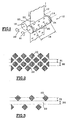
- FIG. 1 shows a device 10 in which a sheet of paper 12 is marked by passage between two cylinders 14, 16 of parallel axes A1 and A2 which rotate synchronously in opposite directions one with respect to the other around their respective axis.
- the sheet of paper 12 can be replaced by two sheets of paper, and their tightening will then not only aim to mark them but also to make them united. Marking (in the case of embossing) can also increase the absorbency of the paper. In all cases, we will seek to obtain the most aesthetic marking possible.
- the cylindrical surface 22 of one of the cylinders 14 is engraved so as to present a tightening band 18 which comprises a plurality of elements in relief 20.
- the second cylinder 16 called a counter-cylinder, has a smooth cylindrical surface 23.
- This contact zone also designated by the term "nip" is not limited to a straight line generator but is in the form of an axial strip having a certain dimension in the circumferential direction of the cylinders 14, 16 which is also the direction of travel of the sheet of paper 12.
- This contact area varies in particular depending on the nature of the materials constituting the cylinders 14, 16, their diameter and their spacing.
- the engraved cylinder 14 also comprises, on its cylindrical surface 22, two strips of load compensation 24 which are arranged here each at one end axial of the engraved cylinder 14, on either side of the clamping band 18, at outside the area of the cylinder 14 which is opposite the sheet of paper 12.
- FIG. 4 shows in relief the elements in relief of the cylinder surface 14.
- the elements in relief 20 are formed of diamonds or triangles. These are geometric shapes simple but the invention can of course be carried out for reasons of more complex and more ornamental form.
- the elements in relief 20 can for example be produced in the form of a series of points, which decreases the active surface of the tightening band 18 which is truly intended to come into contact with the counter-cylinder 16.
- a load compensation band an area elements in relief provided to compensate for variations in effort driven by the active surface of the clamping band; this area can be made up of independent relief elements (small picot-like elements) arranged discontinuously or alternatively be in the form of a strip keep on going.
- a strip of load compensation 24 is arranged on each side of the strip of marking 18 but, as shown in FIG. 5, one can plan to have only one load compensation strip 24 to one of the axial ends of the cylinder 14, this strip then being more great width.
- Each load compensation strip 24 is therefore intended to come to bear against the cylindrical surface 23 of the counter-cylinder 16, without through the sheet of paper 12 in the embodiment illustrated in Figure 1 and through the sheet of paper in other cases as developed further in the description.
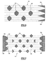
- the active surface load compensating strip 24 corresponds to the part of the strip 24 which is included in the contact zone of the two cylinders or "nip".
- the active surface of the load compensation strip 24 is upgradeable. It varies in direction reverse of the active surface of the clamping band 18 for the same area of contact.
- the variation of the instantaneous active surfaces successive corresponding to the clamping band 18 and the band of load compensation 24 is substantially zero during rotation full of cylinders.
- the interaction force between the two cylinders 14, 16 is substantially constant, which is favorable for good resistance over time cylinders and the entire device.
- the load compensation strip 24 has a first edge 28 which, when developed, is rectilinear, and a second non-rectilinear edge 30 whose profile determines the width of the compensation band charge 24.
- the compensation band load 24 is delimited by two non-straight edges.
- the cylinder circumference is analyzed by successive measurement areas. These zones may correspond in value to a “nip”. But, the bigger the area the finer the measurement, the more the load compensation band accuracy and less the variations in load are important. Therefore, the measurement area is preferably less than "nip”.
- the width of the strip of load compensation 24 may, in some places, be zero. This is produced when, in a contact zone considered, the active surface of the tightening band 18 reaches a maximum value.
- the load compensation strip 24 has a tread area 26 of constant width which in a way constitutes a minimal surface of interaction between the two cylinders 14, 16.
- the rolling zone 26 is for example provided in the center of this strip 24.
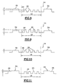
- Figures 8 to 10 show three diagrams illustrating schematically the position of the raised elements of the strip of tightening 18 relative to those of the load compensating strip 24.
- the height elements in relief of the load compensation strip 24 is greater than the height of the raised elements 20 of the tightening band 18.
- the height of the raised elements 20 of the load compensation strip 24 is less than the height of relief elements 20 of the tightening band 18, while, in FIG. 10, the case where the height of the elements in relief of the strip of load compensation 24 is substantially identical to the height of the relief elements of the tightening band 18.
- Figure 11 a diagram which illustrates the case in which the rolling zone 26 is arranged radially more towards inside as the rest of the load compensation strip 24.
- the rolling zone 26 can just as easily be arranged radially at the same level or more outward than the rest of the load compensation strip 24.
- the strip of load compensation 24 and the clamping band 18 are both carried by the same cylinder 14. This is particularly advantageous when the second cylinder 16 is smooth because only one of the two cylinders must be engraved, which makes it possible to carry out the invention without significant additional cost. However, there is nothing to prevent the two bands 18 and 24 from being each carried by one of the cylinders 14, 16. In the case where the strip of load compensation is not located on the cylinder with the relief elements of the tightening band, it is necessary to provide a good angular adjustment between the two cylinders to be able to wedge the strip load compensation with the distribution of the relief elements of the tightening band. Similarly, the rolling area can be carried by the second cylinder 16.
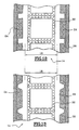
- Figures 12 and 13 illustrate particular embodiments of the device according to the invention, intended for marking the edges of absorbent paper products that are cut into formats. These products are for example napkins or handkerchiefs, Disposable.
- the clamping band 18 of the cylinder 14 comprises zones of border 32 comprising elements in relief intended to mark absorbent paper products made up of at least two folds and to bind these two folds at the edges or peripheral areas of the products in formats.
- a load compensation strip 24 is arranged on the side and on the other side of the tightening band.
- Figures 12 and 13 illustrate two forms possible geometries for load compensation strip 24.
- the load compensation strip 24 also includes a rolling area 26.
- the load compensation strip 24 is arranged in outside of the tightening band 18 of the cylinder 14 opposite which passes the sheet of paper 12 so that the compensation strip of charge 24 does not leave traces on the paper.
- the sheet of paper 12 is intended for the manufacture of paper articles which are of such a dimension that the sheet of paper 12 has drop zones on either side of a useful area of the sheet 12.
- the strip or strips of load compensation 24 can then be provided at least in part, in these drop zones.
- the raised elements of the load compensation strip 24 is sufficiently aesthetic to be able to be kept on the end product of the paper article.
- the compensation band of load 24 is arranged on the cylinder 14 so as to be at least partially in contact with the sheet of paper 12, which will have consequence that the trace of the load compensation strip 24 will be reproduced at least partially on the sheet of paper 12 thus forming additional marking.
- the band of load compensation of elements in relief similar but not identical (for example of different size) to those of the strip of tightening, which we will adapt.
- Figures 15, 16 and 17 illustrate different modes of definition a partial compensation strip that can be used instead of the theoretical compensation band shown in Figure 14 which is moreover of the type delimited by two edges formed by a broken line.
- the strip of theoretical load compensation has been clipped, i.e. all portions of the theoretical strip whose width exceeds a width maximum available are reduced to this so-called maximum width.
- the width of the strip Theoretical load compensation has been reduced by a constant factor of so that the maximum width of the partial compensation strip does not not exceed the maximum width available.
- FIG. 17 shows a third mode of realization of a partial compensation band whose shape is not directly from that of the theoretical band but which allows despite all to decrease the variation of the forces transmitted between the two cylinders 14, 16.
- the shape of the strip load compensation can be obtained from the theoretical form at using a mathematical function.
- the two cylinders of the device according to the invention can be made of the same material or of two different materials. At least one of them is engraved. Both can be made of non-deformable material such as steel or one of non-deformable material and the other of material deformable, for example rubber.
- Each of the cylinders can be made of a single material or several materials.
- the engraved cylinder consists of a part central for engraving the relief elements of the tightening band, made for example of steel, of one or more lateral parts possibly made of another material for the strip load compensation and possibly one or more others parts arranged laterally to the load compensation strips for the rolling area. These other parts can be done in the material of the load compensation bands or in another material. Materials for the load compensation band and for the other parts are non-deformable, identical or different.
- the counter-cylinder comprises a central part produced by rubber example for the raised elements of the band for clamping the engraved cylinder, one or more lateral parts for the with respect to the load compensation strip and, where appropriate, the rolling area. These lateral parts coming into contact with the strip of load and, where applicable, rolling area compensation, can be made of rubber or from one or more other materials.
- the lateral parts corresponding respectively to the strip load compensation and rolling area can be performed in the same or different material.
- the engraved and counterpart cylinders if they are made in the same material, may also have surface treatment areas different.
- the methods using the devices according to the invention can independently lead to deformation of a sheet of paper or the association of several sheets of paper or simultaneously the deformation and association of several sheets, according to characteristics of the process and the installation comprising the devices according to the invention.
- the method implements a device according to the invention in which the sheets are clamped between the two cylinders at the level of the tightening band, with or without adhesive.
- two sheets can be embossed by using two independent or dependent devices, then be associated by setting up work of a third device.
- this third device has at least one cylinder in common (the engraved cylinder) with one of the two first devices used for embossing.
- the first two devices are dependent (have a cylinder in common) and each emboss a sheet; the association is produced by a device consisting of two cylinders each belonging first and second devices respectively.
- the invention also relates to a method of applying an additive such than an adhesive, lotion or ink, on a sheet of paper or nonwoven comprising the use of a device according to the invention.
- the invention thus makes it possible to obtain articles of paper or of nonwoven marked or embossed in a variety of patterns. It provides also products comprising several integral sheets or associated with each other.
Abstract
Description
L'invention concerne un dispositif pour le serrage d'au moins une feuille de papier ou nontissé et trouve application dans la transformation de la feuille en produits finis après sa fabrication par voie humide ou voie sèche.The invention relates to a device for clamping at least one sheet of paper or nonwoven and finds application in processing of the sheet into finished products after its wet or wet production dried.
L'invention concerne plus particulièrement un dispositif pour le serrage d'au moins une feuille de papier ou nontissé, comprenant deux cylindres sensiblement tangents l'un à l'autre, entre lesquels passent la feuille. Dans ce dispositif, au moins un des cylindres comporte sur sa surface dans une zone destinée à être en contact avec la feuille, une bande de serrage comprenant des premiers éléments en relief. L'interaction des deux cylindres avec ou sans la feuille définit une surface active au cours de la rotation des cylindres. Cette surface active sera plus précisément déterminée dans la description qui suit.The invention relates more particularly to a device for clamping at least one sheet of paper or nonwoven, comprising two cylinders substantially tangent to each other, between which pass the leaf. In this device, at least one of the cylinders has on its surface in an area intended to be in contact with the sheet, a strip clamp comprising first elements in relief. The interaction of two cylinders with or without the sheet defines an active surface during the rotation of the cylinders. This active surface will be more precisely determined in the description which follows.
Le document US 5 122 221 A décrit un tel dispositif.Document US 5 122 221 A describes such a device.
On entend par papier tout produit à base de fibres papetières tel que la ouate de cellulose, des produits papetiers absorbants obtenus par voie humide ou par voie sèche. Dans ces derniers, les fibres papetières sont liées par un liant thermoplastique tel qu'un latex ou des fibres thermofusibles. Certains produits papetiers peuvent également comporter des fibres cellulosiques autres que papetières, et parfois même, partiellement, des fibres synthétiques ou artificielles.By paper is meant any product based on paper fibers such as cellulose wadding, absorbent paper products obtained by wet or dry. In these, the paper fibers are bonded by a thermoplastic binder such as latex or fibers melt. Certain paper products may also include cellulosic fibers other than paper, and sometimes even, partially, synthetic or artificial fibers.
Les produits nontissés sont également visés par l'invention.Nonwoven products are also targeted by the invention.
L'invention est plus particulièrement destinée à la fabrication d'articles en ouate de cellulose, et notamment de serviettes en papier, de mouchoirs, de papiers d'essuyage (essuie-tout) ou de papiers toilette.The invention is more particularly intended for manufacturing articles of cellulose wadding, and in particular paper towels, handkerchiefs, wiping paper or toilet paper.
Ces articles sont généralement réalisés à partir d'une ou plusieurs feuilles de papier (ou plis) superposées, qui subissent une opération de serrage. Celle-ci peut avoir plusieurs finalités.These items are generally made from one or more overlapping sheets of paper (or folds), which undergo a Tightening. This can have several purposes.
En effet, dans la suite du texte, le serrage d'une ou plusieurs feuilles
entre deux cylindres (de préférence contrarotatifs) du dispositif, en
fonction des conditions opératoires notamment de pression et de la nature
des cylindres, peut conduire à :
On entend par simple association, le fait de solidariser plusieurs feuilles entre-elles par simple pression, avec ou sans adhésif. Dans le cas d'un encollage, le dispositif comprend un cylindre gravé et un contre-cylindre qui est le cylindre applicateur portant le film de colle.By simple association is meant the fact of joining several sheets between them by simple pressure, with or without adhesive. In the case gluing, the device comprises an engraved cylinder and a counter-cylinder which is the applicator cylinder carrying the adhesive film.
On entend par marquage tout type de déformation de la feuille de papier ou nontissé, susceptible d'être obtenue par le passage de la feuille entre deux cylindres dont l'un au moins est pourvu d'une bande de serrage. En serrant la feuille de papier contre la surface d'un contre-cylindre, la bande de serrage provoque le marquage de la feuille, soit par compression des fibres du papier (marquage au sens strict), soit par déformation en relief (gaufrage), selon des motifs correspondant à des éléments en relief disposés sur la bande de serrage.The term “marking” means any type of deformation of the sheet of paper or nonwoven, capable of being obtained by passing the sheet between two cylinders, at least one of which is provided with a clamping band. By pressing the sheet of paper against the surface of a counter cylinder, the clamping band marks the sheet, either by compression paper fibers (marking in the strict sense), either by deformation in relief (embossing), in patterns corresponding to elements in relief arranged on the tightening band.
Selon les utilisations de ce dispositif, la bande de serrage formera sur le papier ou le nontissé un motif permanent ou non. En effet, au moment même où les cylindres sont en contact l'un avec l'autre par l'intermédiaire de la feuille de papier ou nontissé, la pression quand elle s'exerce, induit un marquage au moyen de la bande de serrage. L'intensité de cette pression (si elle est relativement faible dans le cas d'une association de deux feuilles par exemple) peut être telle que le marquage est léger et n'est pas permanent. Généralement, dans ce cas, aucun marquage n'est visible sur le produit fini. Avec une pression élevée, le marquage devient permanent et visible sur le produit fini.According to the uses of this device, the tightening band will form on paper or nonwoven a permanent pattern or not. Indeed, at moment when the cylinders are in contact with each other by through the sheet of paper or nonwoven, the pressure when it is exerted, induces a marking by means of the tightening band. intensity of this pressure (if it is relatively low in the case of a association of two sheets for example) can be such that the marking is light and is not permanent. Generally, in this case, no marking is visible on the finished product. With high pressure, the marking becomes permanent and visible on the finished product.
La bande de serrage comprend des premiers éléments en relief qui sont gravés sur sa surface cylindrique. Ces éléments peuvent être disposés de manière à former, autour du cylindre, une ou plusieurs zones en relief continues ou non. Ils sont du type géométrique ou non. Ils peuvent être constitués d'éléments unitaires du type tirets, points, lignes continues ou discontinues, ou autres. On peut également envisager de réaliser des motifs par manque d'éléments en relief ou picots. A cette fin, des zones sans picots de la forme du motif souhaité sur le papier, sont prévues sur une surface contenant une répartition régulière de picots.The tightening band includes first raised elements which are engraved on its cylindrical surface. These elements can be arranged so as to form, around the cylinder, one or more raised zones continuous or not. They are of the geometric type or not. They can be made up of unitary elements such as dashes, dots, solid lines or discontinuous, or other. We can also consider carrying out reasons for lack of elements in relief or spikes. To this end, areas without pins of the shape of the desired pattern on the paper, are provided on a surface containing a regular distribution of spikes.
En fonction notamment de la nature du contre-cylindre et de la pression exercée par les cylindres sur la feuille de papier, on peut obtenir des marquages de natures différentes. Depending in particular on the nature of the counter-cylinder and the pressure exerted by the cylinders on the sheet of paper, we can obtain markings of different natures.
Ainsi, le revêtement du contre-cylindre peut être constitué d'un matériau relativement souple par rapport au matériau du revêtement du cylindre portant la bande de serrage. Le contre-cylindre peut encore être réalisé dans un matériau similaire à celui du cylindre portant la bande de serrage. La surface cylindrique externe du contre-cylindre peut être lisse; elle peut être pourvue d'éléments en creux complémentaires des éléments en relief de la bande de serrage ou elle peut être pourvue d'éléments en relief identiques à ceux de la bande de serrage de manière que la feuille de papier soit serrée sous une certaine pression entre deux éléments en relief face à face.Thus, the coating of the counter-cylinder may consist of a relatively flexible material compared to the coating material of the cylinder carrying the tightening band. The counter cylinder can still be made of a material similar to that of the cylinder carrying the strip Tightening. The outer cylindrical surface of the counter cylinder can be smooth; it can be provided with hollow elements complementary to the elements in relief of the tightening band or it can be provided with elements relief identical to those of the tightening strip so that the sheet of paper is clamped under a certain pressure between two elements in relief face to face.
En fonction de ces divers paramètres, la nature du marquage pourra avoir diverses conséquences telles que notamment une augmentation de l'épaisseur du papier (gaufrage), une augmentation du pouvoir absorbant du papier, l'accrochage des différents plis formant la feuille de papier, un marquage particulièrement esthétique ou encore une diminution de l'épaisseur du papier (marquage au sens strict) dans les zones de motif.Depending on these various parameters, the nature of the marking may have various consequences such as in particular an increase in paper thickness (embossing), increased absorbency paper, the attachment of the different folds forming the sheet of paper, a particularly aesthetic marking or a reduction in the thickness of the paper (marking in the strict sense) in the pattern areas.
Dans tous les cas, le serrage de la feuille de papier s'effectue entre deux cylindres d'axes sensiblement parallèles, amenés radialement en appui l'un contre l'autre, et qui sont en rotation lorsque la feuille de papier défile entre les deux cylindres.In all cases, the paper sheet is clamped between two cylinders with substantially parallel axes, brought radially in support one against the other, and which are in rotation when the sheet of paper scrolls between the two cylinders.
Le serrage du papier se fait donc au niveau de la zone de contact des deux cylindres.The paper is therefore clamped at the contact area of the two cylinders.
Cette zone de contact, qui, en théorie, est une ligne parallèle aux axes de rotation des deux cylindres, est en réalité une zone qui présente une certaine largeur selon la circonférence des cylindres (diamètre) et leur laize, la pression exercée entre les cylindres, la nature et les caractéristiques (épaisseur, dureté...) des revêtements des cylindres et les caractéristiques (épaisseur) du papier ou nontissé qui est serré. Cette zone présente ainsi la forme d'une bande de contact qui s'étend axialement le long d'une génératrice principale de contact. La forme de cette zone n'est pas nécessairement homogène sur la laize, elle peut être rectangulaire, creusée au centre, bombée au centre, etc. Cette zone de pincement en forme de bande de contact des deux cylindres est généralement désignée par le terme anglais "nip".This contact area, which, in theory, is a line parallel to the axes of rotation of the two cylinders, is actually an area which presents a certain width depending on the circumference of the cylinders (diameter) and their width, the pressure exerted between the cylinders, the nature and the characteristics (thickness, hardness, etc.) of the cylinder linings and the characteristics (thickness) of the paper or nonwoven which is tight. This zone thus has the form of a contact strip which extends axially the along a main contact generator. The shape of this area is not not necessarily homogeneous on the width, it can be rectangular, excavated in the center, domed in the center, etc. This pinch area in form of contact strip of the two cylinders is generally designated by the English term "nip".
Il est à noter que lorsque l'épaisseur de la feuille de papier ou nontissé est supérieure à l'intervalle existant entre les deux cylindres, le « nip » ou zone de pincement peut également exister entre les cylindres, le contact se faisant par l'intermédiaire de la feuille.It should be noted that when the thickness of the sheet of paper or nonwoven is greater than the interval between the two cylinders, the "Nip" or pinch zone may also exist between the cylinders, the contact made through the sheet.
Le document GB 1 474 101 A montre différents types de marquage qui peuvent être réalisés sur une feuille de papier ou nontissé. GB 1 474 101 A shows different types of marking which can be made on a sheet of paper or nonwoven.
Au cours de leur rotation, les deux cylindres interagissent entre-eux avec ou sans la feuille, et déterminent une surface active engendrée notamment par les éléments en relief disposés en surface des cylindres. Plus précisément, la surface active correspondant à la bande de serrage comprend la surface des éléments en relief qui se trouvent en contact avec la contrepartie par l'intermédiaire de la feuille de papier et, le cas échéant, en particulier lorsque la contrepartie est du type caoutchouc, la surface d'une partie des zones situées entre les éléments en relief, zones qui par la déformation de la contrepartie et du papier, peuvent également être en contact avec la contrepartie par l'intermédiaire de la feuille de papier. Dans ce dernier cas, la pression exercée varie entre le sommet des éléments en relief et les zones de contact entre les éléments en relief.During their rotation, the two cylinders interact with each other with or without the sheet, and determine an active surface generated in particular by the elements in relief arranged on the surface of the cylinders. More specifically, the active surface corresponding to the tightening band includes the surface of the raised elements which are in contact with the consideration via the sheet of paper and, where applicable, especially when the counterpart is of the rubber type, the surface a part of the zones located between the elements in relief, zones which by the deformation of the counterpart and the paper, can also be contact with the counterparty via the sheet of paper. In the latter case, the pressure exerted varies between the top of the raised elements and the contact zones between the raised elements.
A chaque nip sera associée une surface active que l'on qualifiera de surface active instantanée.Each nip will be associated with an active surface which we will describe as instant active surface.
Ainsi, les surfaces actives instantanées successives par lesquelles les deux cylindres coopèrent l'un avec l'autre, varient en fonction des éléments en relief de la bande de serrage mais aussi en fonction de la superficie de la zone de contact.Thus, the successive instantaneous active surfaces by which the two cylinders cooperate with each other, vary depending on the elements in relief of the tightening band but also depending on the area of the contact area.
On a illustré par les figures 2 et 3 deux exemples de disposition possible des éléments en relief pour une bande de serrage.Illustrated by Figures 2 and 3 two examples of arrangement possible elements in relief for a tightening band.
Pour les dispositions illustrées aux figures 2 et 3, on a délimité deux bandes B1 et B2 qui représentent la zone de contact des deux cylindres pour deux positions angulaires différentes de ces deux cylindres.For the arrangements illustrated in Figures 2 and 3, we have delimited two bands B1 and B2 which represent the contact area of the two cylinders for two different angular positions of these two cylinders.
Dans l'exemple de la figure 2, si l'on considère les zones de contact B1, B2 ; on constate que la surface active instantanée de la bande B1 est identique à celle de la bande B2.In the example of figure 2, if we consider the contact zones B1, B2; it can be seen that the instantaneous active surface of the band B1 is identical to that of strip B2.
Dans l'exemple de la figure 3, les deux bandes B1 et B2 présentent des surfaces actives instantanées successives très différentes étant donné que, contrairement à la bande B1, la surface des éléments en relief de la bande B2 est nulle.In the example of Figure 3, the two bands B1 and B2 have very different successive instantaneous active surfaces given that, unlike strip B1, the surface of the raised elements of the band B2 is zero.
Dans la position angulaire des cylindres correspondant à la bande B2, dans le cas d'un travail en pression des cylindres, il y a une interaction entre ces deux cylindres en contact mais elle est très différente de l'interaction de ces mêmes cylindres dans la position angulaire correspondant à la bande B1. Pour la disposition des éléments en relief selon la figure 3, les efforts encaissés par les cylindres varient donc fortement dans le temps au cours de la rotation des cylindres.In the angular position of the cylinders corresponding to the strip B2, in the case of working in pressure of the cylinders, there is a interaction between these two cylinders in contact but it is very different of the interaction of these same cylinders in the angular position corresponding to band B1. For the arrangement of elements in relief according to Figure 3, the forces collected by the cylinders therefore vary strongly in time during the rotation of the cylinders.
Une telle variation des efforts d'interaction entre les deux cylindres qui permettent ici le serrage, est très défavorable à la résistance et au vieillissement des cylindres et de toute l'installation en général (création de vibrations). Le problème se pose dans de nombreux dispositifs permettant le serrage d'une feuille de papier ou nontissé entre deux cylindres dont l'un au moins a une surface gravée.Such a variation in the interaction forces between the two cylinders which allow tightening here, is very unfavorable to the resistance and aging of the cylinders and of the entire installation in general (creation vibrations). The problem arises in many devices allowing the clamping of a sheet of paper or nonwoven between two cylinders, at least one of which has an engraved surface.
L'invention a donc pour but de proposer une amélioration des dispositifs de serrage d'une feuille de papier ou nontissé qui permet d'assurer une durée de vie plus importante des cylindres et de l'ensemble de l'installation. L'invention a également pour but de permettre la réalisation sur la feuille de motifs extrêmement variés, en se dégageant de toute contrainte quant à la régularité des efforts d'interaction entre les cylindres induits par les éléments en relief, qui réduit le choix des motifs.The object of the invention is therefore to propose an improvement in clamping devices for a sheet of paper or nonwoven which allows ensure a longer service life for the cylinders and the assembly of the installation. The invention also aims to allow the extremely varied patterns on the sheet, emerging from any constraint as to the regularity of the interaction efforts between the cylinders induced by the elements in relief, which reduces the choice of patterns.
Ainsi, des motifs de densité, répartition et formes différentes peuvent être maintenant choisis.Thus, patterns of density, distribution and different shapes can now be chosen.
Dans ce but, l'invention propose un dispositif de serrage d'une feuille de papier ou nontissé, du type décrit précédemment, caractérisé en ce que l'un au moins des cylindres comporte sur sa surface dans une zone destinée à être en contact avec l'autre cylindre par l'intermédiaire ou non de la feuille, une bande de compensation de charge comprenant des seconds éléments en relief et choisie de façon que la variation des surfaces actives instantanées successives correspondant à la bande de serrage et à la bande de compensation de charge, soit inférieure à la variation des surfaces actives instantanées successives correspondant à la seule bande de serrage.To this end, the invention provides a device for tightening a sheet of paper or nonwoven, of the type described above, characterized in what at least one of the cylinders has on its surface in an area intended to be in contact with the other cylinder via or not of the sheet, a load compensation strip comprising second elements in relief and chosen so that the variation of the surfaces successive instantaneous assets corresponding to the tightening band and the load compensation band, i.e. less than the variation of successive instantaneous active surfaces corresponding to the single band of Tightening.
Selon d'autres caractéristiques de l'invention, prises seules ou en combinaison :
- la variation des surfaces actives instantanées successives correspondant à la bande de serrage et à la bande de compensation de charge est sensiblement nulle ;
- la largeur de la surface active correspondant à la seule bande de compensation de charge varie, le long de la circonférence du cylindre sur lequel cette bande a été créée, en fonction de la surface active instantanée correspondant à la seule bande de serrage;
- les deux cylindres sont contrarotatifs ;
- les premiers éléments en relief de la bande de serrage sont identiques ou différents des seconds éléments en relief de la bande de compensation de charge ;
- la bande de compensation de charge est agencée sur un cylindre en dehors de la bande de serrage ;
- les seconds éléments en relief de la bande de compensation de charge sont différents des premiers éléments en relief de la bande de serrage et la bande de compensation de charge chevauche au moins partiellement la bande de serrage ;
- au moins un des cylindres porte au moins une bande de serrage et au moins une bande de compensation de charge ;
- la hauteur des éléments en relief de la bande de compensation de charge est sensiblement identique à la hauteur des éléments en relief de la bande de serrage ;
- la hauteur des éléments en relief de la bande de compensation de charge est supérieure à la hauteur des éléments en relief de la bande de serrage ;
- la hauteur des éléments en relief de la bande de compensation de charge est inférieure à la hauteur des éléments en relief de la bande de serrage ;
- la bande de compensation de charge comporte une zone de roulement qui détermine une largeur minimale de la surface active de la bande de compensation de charge ;
- la zone de roulement de la bande de compensation de charge est agencée radialement au même niveau que le reste de la bande de compensation de charge ;
- la zone de roulement de la bande de compensation de charge est agencée radialement vers l'extérieur par rapport au reste de la bande de compensation de charge ;
- la zone de roulement de la bande de compensation de charge est agencée radialement vers l'intérieur par rapport au reste de la bande de compensation de charge ;
- plusieurs bandes de compensation de charge sont prévues sur le même cylindre ;
- chacune des bandes de compensation de charge comporte une zone de roulement.
- the variation of the successive instantaneous active surfaces corresponding to the clamping band and to the load compensation band is substantially zero;
- the width of the active surface corresponding to the single load compensation strip varies, along the circumference of the cylinder on which this strip was created, as a function of the instantaneous active surface corresponding to the single clamping strip;
- the two cylinders are counter-rotating;
- the first raised elements of the clamping band are identical or different from the second raised elements of the load compensation band;
- the load compensating strip is arranged on a cylinder outside the clamping strip;
- the second raised elements of the load compensating strip are different from the first raised elements of the tightening strip and the load compensating strip at least partially overlaps the tightening strip;
- at least one of the cylinders carries at least one clamping band and at least one load compensation band;
- the height of the raised elements of the load compensating strip is substantially identical to the height of the raised elements of the tightening strip;
- the height of the raised elements of the load compensating strip is greater than the height of the raised elements of the clamping strip;
- the height of the raised elements of the load compensating strip is less than the height of the raised elements of the clamping strip;
- the load compensating strip has a tread area which determines a minimum width of the active surface of the load compensating strip;
- the tread of the load compensating strip is arranged radially at the same level as the rest of the load compensating strip;
- the tread area of the load compensating strip is arranged radially outward with respect to the rest of the load compensating strip;
- the tread of the load compensating strip is arranged radially inwardly relative to the rest of the load compensating strip;
- several load compensation bands are provided on the same cylinder;
- each of the load compensation bands has a rolling zone.
L'invention concerne aussi un cylindre pour le serrage d'une feuille de papier ou nontissé, caractérisé en ce qu'il comporte une bande de compensation de charge selon l'une quelconque des caractéristiques ci-dessus.The invention also relates to a cylinder for clamping a sheet. of paper or nonwoven, characterized in that it comprises a strip of load compensation according to any of the above characteristics.
L'invention concerne également une installation comprenant au moins un dispositif selon l'une quelconque des caractéristiques précitées.The invention also relates to an installation comprising at at least one device according to any one of the aforementioned characteristics.
L'invention concerne encore un procédé d'association d'au moins deux feuilles de papier ou nontissé, caractérisé en ce qu'il comporte la mise en oeuvre d'un dispositif comportant l'une quelconque de ces caractéristiques, dans lequel les feuilles sont serrées entre les deux cylindres au niveau de la bande de serrage avec ou sans apport d'adhésif.The invention also relates to a method of associating at least two sheets of paper or nonwoven, characterized in that it comprises the implementation of a device comprising any one of these characteristics, in which the sheets are sandwiched between the two cylinders at the clamping band with or without adhesive.
L'invention vise également un procédé de marquage d'au moins une feuille de papier ou nontissé, caractérisé en ce qu'il comporte la mise en oeuvre d'un dispositif comportant ces mêmes caractéristiques, dans lequel la bande de serrage réalise sur le papier ou nontissé un motif par déformation de la feuille qui est serrée entre les deux cylindres.The invention also relates to a method of marking at least one sheet of paper or nonwoven, characterized in that it includes the setting work of a device comprising these same characteristics, in which the tightening band creates a pattern on the paper or nonwoven deformation of the sheet which is clamped between the two cylinders.
L'invention englobe également tout procédé mettant en oeuvre le dispositif selon l'invention pour appliquer des additifs sur une feuille de papier ou nontissé.The invention also encompasses any method implementing the device according to the invention for applying additives to a sheet of paper or nonwoven.
L'invention concerne aussi un procédé de fabrication d'articles en ouate de cellulose comportant au moins deux feuilles, caractérisé en ce que les feuilles sont rendues solidaires les unes aux autres par un procédé de marquage, gaufrage ou association.The invention also relates to a method for manufacturing articles made of cellulose wadding comprising at least two sheets, characterized in that the sheets are made integral with each other by a process of marking, embossing or association.
D'autres caractéristiques et avantages de l'invention apparaítront plus clairement à la lecture de la description détaillée qui suit et des dessins annexés dans lesquels :
- la figure 1 est une vue schématique en perspective illustrant le principe d'un dispositif de serrage d'une feuille de papier par passage de la feuille entre deux cylindres ;
- les figures 2 et 3 sont deux exemples de disposition d'éléments en relief pour une bande de serrage ;
- les figures 4, 5 et 6 sont des représentations schématiques illustrant les surfaces actives d'une bande de serrage et d'au moins une bande de compensation de charge prévues sur un cylindre d'un dispositif selon l'invention ;
- la figure 7 est une vue similaire à celle des figures 4 à 6 dans lesquelles les bandes de compensation de charge du dispositif comportent une zone de roulement ;
- les figures 8 à 10 sont des diagrammes illustrant de manière schématique différentes positions des éléments en relief de la bande de serrage par rapport à ceux de la bande de compensation de charge ;
- la figure 11 est un diagramme similaire à celui des figures 8 à 10 illustrant un exemple d'une position relative possible, selon la direction radiale, de la zone de roulement d'une bande de compensation de charge par rapport à cette bande de compensation de charge ;
- les figures 12 et 13 sont des représentations schématiques illustrant les surfaces actives d'une bande de serrage, de deux bandes de compensation de charge et de deux zones de roulement prévues sur un cylindre d'un dispositif destiné au marquage des bordures de produits en formats ; et
- les figures 15 à 17 illustrent des bandes de compensation de charge partielles susceptibles d'être utilisées en remplacement de la bande de compensation de charge théorique représentée à la figure 14.
- Figure 1 is a schematic perspective view illustrating the principle of a device for clamping a sheet of paper by passing the sheet between two cylinders;
- Figures 2 and 3 are two examples of arrangement of elements in relief for a clamping band;
- Figures 4, 5 and 6 are schematic representations illustrating the active surfaces of a clamping band and at least one load compensation band provided on a cylinder of a device according to the invention;
- FIG. 7 is a view similar to that of FIGS. 4 to 6 in which the load compensation strips of the device comprise a rolling zone;
- Figures 8 to 10 are diagrams schematically illustrating different positions of the raised elements of the clamping band relative to those of the load compensation band;
- FIG. 11 is a diagram similar to that of FIGS. 8 to 10 illustrating an example of a possible relative position, in the radial direction, of the rolling zone of a load compensation strip with respect to this tire compensation strip charge ;
- Figures 12 and 13 are schematic representations illustrating the active surfaces of a clamping band, two load compensation bands and two rolling zones provided on a cylinder of a device intended for marking the edges of products in formats ; and
- FIGS. 15 to 17 illustrate partial load compensation strips which can be used to replace the theoretical load compensation strip shown in FIG. 14.
Dans la description qui suit, un exemple de dispositif de serrage illustre plus précisément l'invention. Ce dispositif entraíne la déformation d'une feuille de papier, en l'occurrence son marquage.In the following description, an example of a clamping device more specifically illustrates the invention. This device causes deformation a sheet of paper, in this case its marking.
On a représenté sur la figure 1 un dispositif 10 dans lequel une
feuille de papier 12 est marquée par passage entre deux cylindres 14, 16
d'axes parallèles A1 et A2 qui tournent de façon synchrone en sens inverse
l'un par rapport à l'autre autour de leur axe respectif.FIG. 1 shows a
La feuille de papier 12 peut être remplacée par deux feuilles de
papier, et leur serrage aura alors non seulement pour but de les marquer
mais également de les rendre solidaires. Le marquage (dans le cas du
gaufrage) peut aussi permettre d'augmenter le pouvoir absorbant du papier.
Dans tous les cas, on cherchera à obtenir un marquage le plus esthétique
possible.The sheet of
Dans l'exemple représenté, la surface cylindrique 22 de l'un des
cylindres 14 est gravée de manière à présenter une bande de serrage 18 qui
comporte une pluralité d'éléments en relief 20.In the example shown, the
Dans cet exemple de réalisation, le second cylindre 16, dit contre-cylindre,
comporte une surface cylindrique 23 lisse.In this exemplary embodiment, the
Les deux cylindres 14 et 16 coopèrent l'un avec l'autre par une zone
de contact de leur surface cylindrique 22, 23. Cette zone de contact,
désignée également par le terme "nip", n'est pas limitée à une droite
génératrice mais se présente sous la forme d'une bande axiale possédant
une certaine dimension selon la direction circonférentielle des cylindres
14, 16 qui est aussi la direction de défilement de la feuille de papier 12.The two
Pour chaque position angulaire des cylindres 14, 16, correspondant
par ailleurs à une position particulière de la feuille de papier selon la
direction de défilement, les éléments en relief 20 de la bande de serrage 18
qui sont situés dans la zone de contact ou "nip", sont donc au contact de la
feuille de papier 12 et provoquent un serrage de portions de celle-ci contre
la surface cylindrique 23 du contre-cylindre 16.For each angular position of the
La dimension de cette zone de contact selon la direction
circonférentielle varie notamment en fonction de la nature des matériaux
constitutifs des cylindres 14, 16, de leur diamètre et de leur écartement.The size of this contact area according to the direction
circumferential varies in particular depending on the nature of the materials
constituting the
Conformément aux enseignements de l'invention, le cylindre gravé
14 comporte aussi, sur sa surface cylindrique 22, deux bandes de
compensation de charge 24 qui sont agencées ici chacune à une extrémité
axiale du cylindre gravé 14, de part et d'autre de la bande de serrage 18, à
l'extérieur de la zone du cylindre 14 qui est en regard de la feuille de
papier 12.In accordance with the teachings of the invention, the engraved
Pour les figures 4, 5 et 6, les surfaces actives correspondent uniquement aux éléments en relief.For Figures 4, 5 and 6, the active surfaces correspond only in relief.
La figure 4 représente en développé les éléments en relief de la
surface du cylindre 14.FIG. 4 shows in relief the elements in relief of the
Dans cet exemple de réalisation, les éléments en relief 20 sont
formés de losanges ou de triangles. Ce sont des formes géométriques
simples mais l'invention peut bien entendu être réalisée pour des motifs de
forme plus complexe et plus ornementale. De plus, les éléments en relief
20 peuvent par exemple être réalisés sous la forme d'une série de points,
ce qui diminue la surface active de la bande de serrage 18 qui est
véritablement destinée à venir au contact du contre-cylindre 16.In this exemplary embodiment, the elements in
Il est à noter que, pour la bande de serrage, certaines dispositions d'éléments en relief composées uniquement de points, peuvent être plus denses que d'autres dispositions d'éléments formés de lignes et donc présenter une surface active plus importante. Une même disposition composée de lignes transformées en points peut permettre de diminuer la surface active de la bande de serrage qui est destinée à venir au contact du contre-cylindre par l'intermédiaire de la feuille de papier.It should be noted that, for the tightening band, certain provisions raised elements composed only of dots, can be more dense as other arrangements of elements formed of lines and therefore have a larger active surface. One layout composed of lines transformed into points can reduce the active surface of the tightening strip which is intended to come into contact with the counter cylinder through the sheet of paper.
On qualifie de bande de compensation de charge, une zone d'éléments en relief prévue pour compenser les variations d'efforts entraínés par la surface active de la bande de serrage ; cette zone peut être constituée d'éléments en relief indépendants (petits éléments de type picot) disposés de manière discontinue ou encore être sous la forme d'une bande continue.We call a load compensation band, an area elements in relief provided to compensate for variations in effort driven by the active surface of the clamping band; this area can be made up of independent relief elements (small picot-like elements) arranged discontinuously or alternatively be in the form of a strip keep on going.
Dans l'exemple de réalisation de la figure 4, une bande de
compensation de charge 24 est agencée de chaque côté de la bande de
marquage 18 mais, ainsi que cela est représenté sur la figure 5, on peut
prévoir de ne disposer qu'une seule bande de compensation de charge 24 à
l'une des extrémités axiales du cylindre 14, cette bande étant alors de plus
grande largeur.In the exemplary embodiment of FIG. 4, a strip of
Chaque bande de compensation de charge 24 est donc destinée à
venir en appui contre la surface cylindrique 23 du contre-cylindre 16, sans
l'intermédiaire de la feuille de papier 12 dans le mode de réalisation
illustré à la figure 1 et par l'intermédiaire de la feuille de papier dans
d'autres cas comme cela est développé plus loin dans la description. Pour
chaque position angulaire des cylindres 14, 16, la surface active
instantanée de la bande de compensation de charge 24 correspond à la
partie de la bande 24 qui est comprise dans la zone de contact des deux
cylindres ou "nip".Each
Comme on peut le voir sur les figures 4 à 6, la surface active de la
bande de compensation de charge 24 est évolutive. Elle varie en sens
inverse de la surface active de la bande de serrage 18 pour la même zone
de contact.As can be seen in Figures 4 to 6, the active surface of the
Dans cet exemple, la variation des surfaces actives instantanées
successives correspondant à la bande de serrage 18 et à la bande de
compensation de charge 24 est sensiblement nulle au cours de la rotation
complète des cylindres.In this example, the variation of the instantaneous active surfaces
successive corresponding to the clamping
Ainsi, l'effort d'interaction entre les deux cylindres 14, 16 est
sensiblement constant, ce qui est favorable à la bonne tenue dans le temps
des cylindres et de l'ensemble du dispositif.Thus, the interaction force between the two
Dans les exemples de réalisation de l'invention représentés aux
figures 4 à 6, la bande de compensation de charge 24 comporte un premier
bord 28 qui, en développé, est rectiligne, et un second bord non rectiligne
30 dont le profil détermine la largeur de la bande de compensation de
charge 24. Toutefois, on peut aussi prévoir que la bande de compensation
de charge 24 soit délimitée par deux bords non rectilignes.In the exemplary embodiments of the invention shown in
Figures 4 to 6, the
Pour définir la forme de la bande de compensation de charge, la circonférence du cylindre est analysée par zones de mesures successives. Ces zones pourront correspondre en valeur à un « nip ». Mais, plus la zone de mesure est fine, plus la bande de compensation de charge gagne en précision et moins les variations de charge sont importantes. De ce fait, la zone de mesure est de préférence inférieure au « nip ».To define the shape of the load compensation strip, the cylinder circumference is analyzed by successive measurement areas. These zones may correspond in value to a “nip”. But, the bigger the area the finer the measurement, the more the load compensation band accuracy and less the variations in load are important. Therefore, the measurement area is preferably less than "nip".
Comme on peut le voir sur la figure 6, la largeur de la bande de
compensation de charge 24 peut, à certains endroits, être nulle. Cela se
produit lorsque, dans une zone de contact considérée, la surface active de
la bande de serrage 18 atteint une valeur maximale. As can be seen in Figure 6, the width of the strip of
Toutefois, pour améliorer la tenue dans le temps des revêtements
des cylindres 14, 16, il est souhaitable d'éviter de telles zones où la bande
de compensation 24 est interrompue. En effet, la discontinuité locale
d'efforts due à l'interruption de la bande de compensation de charge peut
être, à la longue, nuisible au revêtement du cylindre.However, to improve the resistance over time of
Comme cela est représenté à la figure 7, on peut aussi prévoir que la
bande de compensation de charge 24 comporte une zone de roulement 26
de largeur constante qui constitue en quelque sorte une surface minimale
d'interaction entre les deux cylindres 14, 16.As shown in Figure 7, we can also provide that the
Cette zone de roulement 26, de préférence adjacente au reste de la
bande de compensation de charge 24, s'étend ainsi de manière continue
autour de l'axe du cylindre.This rolling
Lorsque la bande de compensation de charge 24 présente deux bords
non rectilignes, la zone de roulement 26 est par exemple prévue au centre
de cette bande 24.When the
On a représenté sur les figures 8 à 10 trois diagrammes illustrant de
manière schématique la position des éléments en relief de la bande de
serrage 18 par rapport à ceux de la bande de compensation de charge 24.Figures 8 to 10 show three diagrams illustrating
schematically the position of the raised elements of the strip of
tightening 18 relative to those of the
Dans l'exemple de réalisation représenté sur la figure 8, la hauteur
des éléments en relief de la bande de compensation de charge 24 est
supérieure à la hauteur des éléments en relief 20 de la bande de serrage 18.
Au contraire, dans la figure 9, la hauteur des éléments en relief 20 de la
bande de compensation de charge 24 est inférieure à la hauteur des
éléments en relief 20 de la bande de serrage 18, tandis que, à la figure 10,
on a représenté le cas où la hauteur des éléments en relief de la bande de
compensation de charge 24 est sensiblement identique à la hauteur des
éléments en relief de la bande de serrage 18.In the embodiment shown in Figure 8, the height
elements in relief of the
On a représenté sur la figure 11 un diagramme qui illustre le cas
dans lequel la zone de roulement 26 est agencée radialement plus vers
l'intérieur que le reste de la bande de compensation de charge 24.
Toutefois, la zone de roulement 26 peut tout aussi bien être agencée
radialement au même niveau ou plus vers l'extérieur que le reste de la
bande de compensation de charge 24.There is shown in Figure 11 a diagram which illustrates the case
in which the rolling
Dans les exemples de réalisation des figures 4 à 11, la bande de
compensation de charge 24 et la bande de serrage 18 sont toutes les deux
portées par le même cylindre 14. Cela est particulièrement avantageux
lorsque le second cylindre 16 est lisse car un seul des deux cylindres doit
être gravé, ce qui permet de réaliser l'invention sans surcoût notable.
Toutefois, rien ne s'oppose à ce que les deux bandes 18 et 24 soient
portées chacune par un des cylindres 14, 16. Dans le cas où la bande de
compensation de charge n'est pas située sur le cylindre comportant les
éléments en relief de la bande de serrage, il est nécessaire de prévoir un
bon réglage angulaire entre les deux cylindres pour pouvoir caler la bande
de compensation de charge avec la répartition des éléments en relief de la
bande de serrage. De même, la zone de roulement peut être portée par le
second cylindre 16.In the exemplary embodiments of FIGS. 4 to 11, the strip of
Les figures 12 et 13 illustrent des modes de réalisation particuliers du dispositif selon l'invention, destiné au marquage des bordures de produits en papier absorbant qui sont découpés en formats. Ces produits sont par exemple des serviettes de table ou des mouchoirs en papier, jetables.Figures 12 and 13 illustrate particular embodiments of the device according to the invention, intended for marking the edges of absorbent paper products that are cut into formats. These products are for example napkins or handkerchiefs, Disposable.
La bande de serrage 18 du cylindre 14 comprend des zones de
bordure 32 comportant des éléments en relief destinés à marquer des
produits en papier absorbant constitués d'au moins deux plis et à lier ces
deux plis au niveau des bordures ou zones périphériques des produits en
formats.The clamping
Ici, une bande de compensation de charge 24 est agencée de part et
d'autre de la bande de serrage. Les figures 12 et 13 illustrent deux formes
géométriques possibles pour la bande de compensation de charge 24.Here, a
La bande de compensation de charge 24 comporte également une
zone de roulement 26.The
Il a été vu que, dans les modes de réalisation envisagés
précédemment, la bande de compensation de charge 24 est agencée en
dehors de la bande de serrage 18 du cylindre 14 en regard de laquelle
passe la feuille de papier 12 si bien que la bande de compensation de
charge 24 ne laisse pas subsister de traces sur le papier.It has been seen that, in the embodiments envisaged
previously, the
Toutefois, dans certaines applications, la feuille de papier 12 est
destinée à la fabrication d'articles en papier qui sont d'une dimension telle
que la feuille de papier 12 comporte des zones de chute de part et d'autre
d'une zone utile de la feuille 12. Éventuellement, la ou les bandes de
compensation de charge 24 pourront alors être prévues au moins en partie,
dans ces zones de chute.However, in some applications, the sheet of
Enfin, dans le cas où les seconds éléments en relief de la bande de
compensation de charge se distinguent des premiers éléments en relief de
la bande de serrage, il se peut que pour certains motifs marqués sur le
produit fini, les éléments en relief de la bande de compensation de charge
24 présente un caractère suffisamment esthétique pour pouvoir être
conservés sur le produit final que constitue l'article en papier. Dans ce cas,
on pourra avantageusement prévoir que la bande de compensation de
charge 24 soit agencée sur le cylindre 14 de manière à être au moins
partiellement en contact avec la feuille de papier 12, ce qui aura pour
conséquence que la trace de la bande de compensation de charge 24 sera
reproduite au moins partiellement sur la feuille de papier 12 formant ainsi
un marquage complémentaire. On pourra choisir pour la bande de
compensation de charge des éléments en relief similaires mais non
identiques (par exemple de dimension différente) à ceux de la bande de
serrage, que l'on adaptera.Finally, in the case where the second elements in relief of the strip of
load compensation are distinguished from the first relief elements of
the band, it may be that for certain reasons marked on the
finished product, the raised elements of the
En fonction de la disposition des éléments en relief de la bande de
serrage 18, il peut s'avérer que la largeur de la bande de compensation de
charge 24 nécessaire pour équilibrer l'effort d'interaction des cylindres 14,
16 soit excessive par rapport à la place disponible sur le cylindre 14. Dans
ce cas, on peut se contenter d'utiliser une ou plusieurs bandes de
compensation partielles qui ne compensent pas entièrement les variations
des surfaces actives instantanées successives de la bande de serrage au
cours de la rotation des deux cylindres 14 et 16 mais qui permettent
malgré tout de les limiter dans des proportions importantes afin d'atteindre
l'objectif d'augmentation de la durée de vie des cylindres. Dans ce cas, la
variation des surfaces actives instantanées successives correspondant à la
bande de serrage et à la bande de compensation de charge est inférieure à
la variation des surfaces actives instantanées successives correspondant à
la seule bande de serrage 18.Depending on the arrangement of the relief elements of the strip
tightening 18, it may turn out that the width of the
Les figures 15, 16 et 17 illustrent différents modes de définition d'une bande de compensation partielle susceptible d'être utilisée à la place de la bande de compensation théorique représentée à la figure 14 qui est par ailleurs du type délimité par deux bords formés par une ligne brisée.Figures 15, 16 and 17 illustrate different modes of definition a partial compensation strip that can be used instead of the theoretical compensation band shown in Figure 14 which is moreover of the type delimited by two edges formed by a broken line.
Dans l'exemple de réalisation de la figure 15, la bande de compensation de charge théorique a été écrêtée, c'est-à-dire que toutes les portions de la bande théorique dont la largeur dépasse une largeur maximale disponible sont ramenées à cette dite largeur maximale.In the exemplary embodiment of FIG. 15, the strip of theoretical load compensation has been clipped, i.e. all portions of the theoretical strip whose width exceeds a width maximum available are reduced to this so-called maximum width.
Dans l'exemple de réalisation de la figure 16, la largeur de la bande de compensation de charge théorique a été réduite d'un facteur constant de manière que la largeur maximale de la bande de compensation partielle ne dépasse pas la largeur maximale disponible. Dans cet exemple de réalisation, on a réduit la bande de compensation de charge en gardant sensiblement la forme de la bande de compensation de charge théorique.In the embodiment of FIG. 16, the width of the strip Theoretical load compensation has been reduced by a constant factor of so that the maximum width of the partial compensation strip does not not exceed the maximum width available. In this example of realization, we reduced the load compensation band keeping substantially the shape of the theoretical load compensation strip.
Enfin, on a représenté sur la figure 17 un troisième mode de
réalisation d'une bande de compensation partielle dont la forme n'est pas
directement issue de celle de la bande théorique mais qui permet malgré
tout de diminuer la variation des efforts transmis entre les deux cylindres
14, 16. Suivant ce mode de réalisation, il est possible de favoriser un des
paramètres de la bande de compensation de charge : les zones où la surface
active de la bande de compensation de charge est nulle, les zones où elle
est maximale, les zones de transition, etc. La forme de la bande de
compensation de charge peut être obtenue à partir de la forme théorique à
l'aide d'une fonction mathématique.Finally, FIG. 17 shows a third mode of
realization of a partial compensation band whose shape is not
directly from that of the theoretical band but which allows despite
all to decrease the variation of the forces transmitted between the two
Les deux cylindres du dispositif selon l'invention peuvent être constitués d'un même matériau ou de deux matériaux différents. Au moins l'un des deux est gravé. Les deux peuvent être en matériau non déformable tel que l'acier ou l'un en matériau non déformable et l'autre en matériau déformable par exemple en caoutchouc.The two cylinders of the device according to the invention can be made of the same material or of two different materials. At least one of them is engraved. Both can be made of non-deformable material such as steel or one of non-deformable material and the other of material deformable, for example rubber.
Chacun des cylindres peut être constitué d'un matériau unique ou de plusieurs matériaux.Each of the cylinders can be made of a single material or several materials.
Dans ce dernier cas, le cylindre gravé est constitué d'une partie centrale pour la gravure des éléments en relief de la bande de serrage, réalisée par exemple en acier, d'une ou plusieurs parties latérales éventuellement réalisées dans un autre matériau pour la bande de compensation de charge et éventuellement, d'une ou plusieurs autres parties disposées latéralement aux bandes de compensation de charge pour la zone de roulement. Ces autres parties peuvent être réalisées dans le matériau des bandes de compensation de charge ou encore dans un autre matériau. Les matériaux pour la bande de compensation de charge et pour les autres parties sont des matériaux non déformables, identiques ou différents. Le contre-cylindre comprend une partie centrale réalisée par exemple en caoutchouc pour le vis à vis des éléments en relief de la bande de serrage du cylindre gravé, d'une ou plusieurs parties latérales pour le vis à vis de la bande de compensation de charge et, le cas échéant, de la zone de roulement. Ces parties latérales venant au contact de la bande de compensation de charge et, le cas échéant, de la zone de roulement, peuvent être réalisées en caoutchouc ou à partir d'un ou plusieurs autres matériaux. Les parties latérales correspondant respectivement à la bande de compensation de charge et à la zone de roulement peuvent être réalisées dans un matériau identique ou différent.In the latter case, the engraved cylinder consists of a part central for engraving the relief elements of the tightening band, made for example of steel, of one or more lateral parts possibly made of another material for the strip load compensation and possibly one or more others parts arranged laterally to the load compensation strips for the rolling area. These other parts can be done in the material of the load compensation bands or in another material. Materials for the load compensation band and for the other parts are non-deformable, identical or different. The counter-cylinder comprises a central part produced by rubber example for the raised elements of the band for clamping the engraved cylinder, one or more lateral parts for the with respect to the load compensation strip and, where appropriate, the rolling area. These lateral parts coming into contact with the strip of load and, where applicable, rolling area compensation, can be made of rubber or from one or more other materials. The lateral parts corresponding respectively to the strip load compensation and rolling area can be performed in the same or different material.
Les cylindres gravé et contrepartie s'ils sont réalisés dans un même matériau, peuvent encore comporter des zones de traitement de surface différentes. The engraved and counterpart cylinders if they are made in the same material, may also have surface treatment areas different.
Les procédés mettant en oeuvre les dispositifs selon l'invention peuvent indépendamment conduire à la déformation d'une feuille de papier ou à l'association de plusieurs feuilles de papier ou encore simultanément à la déformation et à l'association de plusieurs feuilles, selon les caractéristiques du procédé et l'installation comportant le ou les dispositifs selon l'invention.The methods using the devices according to the invention can independently lead to deformation of a sheet of paper or the association of several sheets of paper or simultaneously the deformation and association of several sheets, according to characteristics of the process and the installation comprising the devices according to the invention.
Dans le cas d'une association d'au moins deux feuilles de papier ou nontissé, le procédé met en oeuvre un dispositif selon l'invention dans lequel les feuilles sont serrées entre les deux cylindres au niveau de la bande de serrage, avec ou sans apport d'adhésif.In the case of a combination of at least two sheets of paper or nonwoven, the method implements a device according to the invention in which the sheets are clamped between the two cylinders at the level of the tightening band, with or without adhesive.
Dans le cas du marquage strict, un seul dispositif constitué de deux cylindres dont l'un est muni d'une bande de serrage, peut suffire.In the case of strict marking, a single device consisting of two cylinders, one of which is fitted with a clamping band, may suffice.
Dans le cas du gaufrage, plusieurs solutions sont possibles. Par exemple, deux feuilles peuvent être gaufrées par la mise en oeuvre de deux dispositifs indépendants ou dépendants, puis être associées par la mise en oeuvre d'un troisième dispositif. De préférence, ce troisième dispositif a au moins un cylindre en commun (le cylindre gravé) avec l'un des deux premiers dispositifs mis en oeuvre pour le gaufrage.In the case of embossing, several solutions are possible. Through example, two sheets can be embossed by using two independent or dependent devices, then be associated by setting up work of a third device. Preferably, this third device has at least one cylinder in common (the engraved cylinder) with one of the two first devices used for embossing.
Suivant un autre mode de réalisation, toujours dans le cas du gaufrage, les deux premiers dispositifs sont dépendants (ont un cylindre en commun) et assurent chacun le gaufrage d'une feuille ; l'association est réalisée par un dispositif constitué de deux cylindres appartenant chacun respectivement aux premier et second dispositifs.According to another embodiment, always in the case of embossing, the first two devices are dependent (have a cylinder in common) and each emboss a sheet; the association is produced by a device consisting of two cylinders each belonging first and second devices respectively.
L'invention vise également un procédé d'application d'un additif tel qu'un adhésif, une lotion ou de l'encre, sur une feuille de papier ou nontissé comportant la mise en oeuvre d'un dispositif selon l'invention.The invention also relates to a method of applying an additive such than an adhesive, lotion or ink, on a sheet of paper or nonwoven comprising the use of a device according to the invention.
L'invention permet ainsi d'obtenir des articles en papier ou en nontissé marqués ou gaufrés suivant des motifs très variés. Elle fournit également des produits comportant plusieurs feuilles solidaires ou associées entre elles.The invention thus makes it possible to obtain articles of paper or of nonwoven marked or embossed in a variety of patterns. It provides also products comprising several integral sheets or associated with each other.
Claims (30)
- Device for clamping at least one paper or non-woven sheet (12) comprising two cylinders (14, 16) substantially tangent to each other, at least one of the cylinders having on its surface, in a zone intended to be in contact with the said sheet (12), a clamping band (18) comprising first salient elements, the interaction of the two cylinders with or without the sheet defining an active surface during the rotation of the cylinders, characterised in that at least one (14) of the cylinders has on its surface, in a zone intended to be in contact with the other cylinder, through the intermediary or not of the sheet, a load compensating band (24) comprising second salient elements and chosen so that the variation of the successive instantaneous active surfaces corresponding to the clamping band (18) and to the load compensating band (24) is less than the variation of the successive instantaneous active surfaces corresponding to the clamping band (18) alone.
- Device according to Claim 1, characterised in that the variation of the successive instantaneous active surfaces corresponding to the clamping band (18) and to the load compensating band (24) is substantially zero.
- Device according to one of the preceding claims, characterised in that the width of the active surface corresponding to the load compensating band (24) alone varies along the circumference of the cylinder on which the said band has been created, as a function of the instantaneous active surface corresponding to the clamping band (18) alone.
- Device according to one of the preceding claims, characterised in that the aforementioned cylinders rotate in opposite directions.
- Device according to one of the preceding claims, characterised in that the first salient elements of the clamping band (18) are identical to or different from the second salient elements of the load compensating band (24).
- Device according to one of the preceding claims, characterised in that the load compensating band (24) is arranged on a cylinder (14) outside the said clamping band (18).
- Device according to one of Claims 1 to 5, characterised in that the second salient elements of the load compensating band differ from the first salient elements of the clamping band and in that the load compensating band (24) at least partly overlaps the clamping band.
- Device according to any one of the preceding claims, characterised in that at least one (14) of the cylinders bears at least one clamping band (18) and at least one load compensating band (24).
- Device according to Claim 8, characterised in that the height of the salient elements of the load compensating band (24) is substantially identical to the height of the salient elements of the clamping band (18).
- Device according to Claim 8, characterised in that the height of the salient elements of the load compensating band (24) is greater than the height of the salient elements of the clamping band (18).
- Device according to Claim 8, characterised in that the height of the salient elements of the load compensating band (24) is less than the height of the salient elements of the clamping band (18).
- Device according to any one of the preceding claims, characterised in that the load compensating band (24) has a rolling zone (26) which determines a minimum width of the active surface of the load compensating band (24).
- Device according to Claim 12, characterised in that the rolling zone (26) of the load compensating band (24) is arranged radially at the same level as the remainder of the load compensating band (24).
- Device according to Claim 12, characterised in that the rolling zone (26) of the load compensating band (24) is arranged radially outwards relative to the remainder of the load compensating band (24).
- Device according to Claim 12, characterised in that the rolling zone (26) of the load compensating band (24) is arranged radially inwards relative to the remainder of the load compensating band (24).
- Device according to any one of the preceding claims, characterised in that a plurality of load compensating bands (24) are provided on the same cylinder.
- Device according to Claim 16, taken in combination with any one of Claims 12 to 15, characterised in that each of the load compensating bands (24) has a rolling zone (26).
- Device according to one of the preceding claims, characterised in that the two cylinders are made of non-deformable material.
- Device according to one of Claims 1 to 17, characterised in that one of the cylinders is made of non-deformable material and the other is made of deformable material.
- Cylinder for clamping a paper or non-woven sheet, characterised in that it forms part of the device according to any one of the preceding claims and in that it has a load compensating band (24).
- Installation comprising at least one clamping device according to one of Claims 1 to 19.
- Installation according to Claim 21, characterised in that it comprises at least two devices according to one of Claims 1 to 19, the said devices being independent of one another.
- Installation according to Claim 21, characterised in that it comprises at least two devices according to one of Claims 1 to 19, at least two of the said devices sharing a cylinder.
- Method for associating at least two paper or non-woven sheets, characterised in that it involves employing a device according to any one of Claims 1 to 19, in which the said sheets are clamped between the two cylinders at the clamping band (18), with or without adhesive being supplied.
- Method for marking at least one paper or non-woven sheet, characterised in that it involves employing a device according to any one of Claims 1 to 19, in which the clamping band (18) produces a pattern on the paper or non-woven by deforming the sheet which is clamped between the two cylinders.
- Method according to Claim 25, characterised in that it involves embossing.
- Method according to Claim 26, characterised in that two paper or non-woven sheets are embossed by respectively employing two independent or dependent devices according to any one of Claims 1 to 19 and are then associated by employing a third device according to any one of Claims 1 to 19.
- Method according to Claim 27, characterised in that the third device shares at least one engraved cylinder with one of the two aforementioned devices employed for the embossing.
- Method for applying an additive, such as an adhesive, a lotion or ink, to a paper or non-woven sheet, characterised in that it involves employing a device according to one of Claims 1 to 19.
- Method for manufacturing cellulose wadding articles having at least two sheets, characterised in that the sheets are joined to one another by a marking, embossing or associating method according to one of Claims 24 to 28.
Priority Applications (9)
| Application Number | Priority Date | Filing Date | Title |
|---|---|---|---|
| PT00401191T PT1151852E (en) | 2000-04-28 | 2000-04-28 | DEVICE AND PROCESS FOR THE TIGHTENING OF PAPER OR NON-FABRIC MATERIAL, AND PRODUCED PRODUCT |
| ES00401191T ES2231135T3 (en) | 2000-04-28 | 2000-04-28 | DEVICE AND PROCEDURE FOR THE TIGHTENING OF PAPER OR NON-WOVEN, AND ARTICLE MANUFACTURED. |
| DK00401191T DK1151852T3 (en) | 2000-04-28 | 2000-04-28 | Apparatus and method for squeezing paper or nonwoven, and manufactured product |
| DE60016175T DE60016175T2 (en) | 2000-04-28 | 2000-04-28 | Apparatus and method for embossing paper or nonwoven fabric, and the product produced |
| EP00401191A EP1151852B1 (en) | 2000-04-28 | 2000-04-28 | Device and method for embossing of paper or nonwovens, and product obtained |
| AT00401191T ATE283166T1 (en) | 2000-04-28 | 2000-04-28 | DEVICE AND METHOD FOR EMBOSSING PAPER OR NON-WOVEN FABRIC, AND THE PRODUCT PRODUCED |
| CA002344261A CA2344261C (en) | 2000-04-28 | 2001-04-18 | Device, cylinder and installation for securing at least one sheet of paper or nonwoven, processes implementing such device and article manufactured according to such processes |
| US09/839,406 US6475346B2 (en) | 2000-04-28 | 2001-04-23 | Apparatus to clamp at least one non-woven or paper sheet, methods implementing such apparatus, and article made by such methods |
| TR2001/01063A TR200101063A3 (en) | 2000-04-28 | 2001-04-26 | Apparatus, cylinder and plant for squeezing at least one paper or non-woven, methods using such an apparatus and the product produced according to these methods |
Applications Claiming Priority (1)
| Application Number | Priority Date | Filing Date | Title |
|---|---|---|---|
| EP00401191A EP1151852B1 (en) | 2000-04-28 | 2000-04-28 | Device and method for embossing of paper or nonwovens, and product obtained |
Publications (2)
| Publication Number | Publication Date |
|---|---|
| EP1151852A1 EP1151852A1 (en) | 2001-11-07 |
| EP1151852B1 true EP1151852B1 (en) | 2004-11-24 |
Family
ID=8173662
Family Applications (1)
| Application Number | Title | Priority Date | Filing Date |
|---|---|---|---|
| EP00401191A Expired - Lifetime EP1151852B1 (en) | 2000-04-28 | 2000-04-28 | Device and method for embossing of paper or nonwovens, and product obtained |
Country Status (9)
| Country | Link |
|---|---|
| US (1) | US6475346B2 (en) |
| EP (1) | EP1151852B1 (en) |
| AT (1) | ATE283166T1 (en) |
| CA (1) | CA2344261C (en) |
| DE (1) | DE60016175T2 (en) |
| DK (1) | DK1151852T3 (en) |
| ES (1) | ES2231135T3 (en) |
| PT (1) | PT1151852E (en) |
| TR (1) | TR200101063A3 (en) |
Families Citing this family (9)
| Publication number | Priority date | Publication date | Assignee | Title |
|---|---|---|---|---|
| US7056404B2 (en) * | 1998-11-25 | 2006-06-06 | The Procter & Gamble Company | Methods of bonding materials, especially materials used in absorbent articles |
| ITFI20020061A1 (en) * | 2002-04-12 | 2003-10-13 | Perini Fabio Spa | DEVICE AND COUPLING METHOD OF VEILS FOR THE FORMATION OF SHEET ITEMS AND MANUFACTURES SO OBTAINED |
| DE102005056109A1 (en) * | 2005-11-23 | 2007-05-24 | WINKLER + DüNNEBIER AG | Embossing roller for multilayer paper handkerchief production, has embossing pins arranged on outer surface and/or with dimensions such that engagement area is constant |
| US8739728B2 (en) * | 2011-04-07 | 2014-06-03 | Dynamic Micro Systems, Semiconductor Equipment Gmbh | Methods and apparatuses for roll-on coating |
| US8764940B2 (en) * | 2012-06-08 | 2014-07-01 | The Procter & Gamble Company | Embossed fibrous structures |
| US20140349056A1 (en) * | 2013-05-22 | 2014-11-27 | The Procter & Gamble Company | Absorbent paper product having visual elements |
| US20140346704A1 (en) * | 2013-05-22 | 2014-11-27 | The Procter & Gamble Company | Method for producing an absorbent paper product having visual elements |
| US11413804B2 (en) * | 2018-02-06 | 2022-08-16 | Xerox Corporation | Method and apparatus for embossing a substrate |
| US20210362458A1 (en) | 2018-05-29 | 2021-11-25 | Jose Antonio LOGIODICE | Improvement to embossing assembly for processing paper |
Family Cites Families (8)
| Publication number | Priority date | Publication date | Assignee | Title |
|---|---|---|---|---|
| US3893795A (en) * | 1970-08-20 | 1975-07-08 | Rowland Dev Corp | Embossing rolls with areas of differential hardness |
| GB1474101A (en) * | 1974-04-26 | 1977-05-18 | Ici Ltd | Non-woven fabrics |
| US4803032A (en) * | 1983-05-17 | 1989-02-07 | James River-Norwalk, Inc. | Method of spot embossing a fibrous sheet |
| IT1225324B (en) * | 1988-11-23 | 1990-11-06 | Perini Finanziaria Spa | PAPER PROCESSING MACHINE WITH COOPERATING EMBOSSING CYLINDERS FOR POINT-TO-POINT COUPLING OF TWO PAPER BELTS EMBOSSED BY THEM |
| JPH077147Y2 (en) * | 1989-06-05 | 1995-02-22 | 株式会社磯輪鉄工所 | Single-sided corrugated board manufacturing equipment |
| IT1278802B1 (en) * | 1995-12-05 | 1997-11-28 | Perini Fabio Spa | EMBOSSING-LAMINATOR GROUP, WITH DISTRIBUTED CONTACT CYLINDERS AND RELATIVE EMBOSSING METHOD |
| US6170393B1 (en) * | 1998-05-21 | 2001-01-09 | The Procter & Gamble Company | Compliant embosser assembly |
| US6251207B1 (en) * | 1998-12-31 | 2001-06-26 | Kimberly-Clark Worldwide, Inc. | Embossing and laminating irregular bonding patterns |
-
2000
- 2000-04-28 ES ES00401191T patent/ES2231135T3/en not_active Expired - Lifetime
- 2000-04-28 DE DE60016175T patent/DE60016175T2/en not_active Expired - Lifetime
- 2000-04-28 PT PT00401191T patent/PT1151852E/en unknown
- 2000-04-28 EP EP00401191A patent/EP1151852B1/en not_active Expired - Lifetime
- 2000-04-28 DK DK00401191T patent/DK1151852T3/en active
- 2000-04-28 AT AT00401191T patent/ATE283166T1/en active
-
2001
- 2001-04-18 CA CA002344261A patent/CA2344261C/en not_active Expired - Fee Related
- 2001-04-23 US US09/839,406 patent/US6475346B2/en not_active Expired - Lifetime
- 2001-04-26 TR TR2001/01063A patent/TR200101063A3/en unknown
Also Published As
| Publication number | Publication date |
|---|---|
| TR200101063A2 (en) | 2001-11-21 |
| CA2344261A1 (en) | 2001-10-28 |
| TR200101063A3 (en) | 2001-11-21 |
| DE60016175D1 (en) | 2004-12-30 |
| US6475346B2 (en) | 2002-11-05 |
| ES2231135T3 (en) | 2005-05-16 |
| CA2344261C (en) | 2009-09-15 |
| PT1151852E (en) | 2005-04-29 |
| US20020060032A1 (en) | 2002-05-23 |
| DE60016175T2 (en) | 2005-12-15 |
| DK1151852T3 (en) | 2005-03-21 |
| EP1151852A1 (en) | 2001-11-07 |
| ATE283166T1 (en) | 2004-12-15 |
Similar Documents
| Publication | Publication Date | Title |
|---|---|---|
| EP0426548B1 (en) | Multi-ply sheet of absorbent paper | |
| EP0679122B1 (en) | Method for embossing a sheet with one or more plies | |
| EP0572503B1 (en) | Paper sheets having several distinct layers with markings and process for producing them | |
| EP1209289B1 (en) | Creped absorbent paper sheet, creping cylinder and process for making such a sheet | |
| CA2458952C (en) | Absorbent paper product with improved embossing | |
| EP1084300B1 (en) | Absorbent paper product comprising three pleats and method for making same | |
| EP0935021B1 (en) | Absorbent household paper | |
| CA2193088C (en) | Absorbent paper multilayered sheet and method of manufacture | |
| EP1325982B1 (en) | Embossed paper sheet | |
| EP1047546B1 (en) | Sheet of embossed absorbent paper, and a method and device for producing same | |
| EP1270196B1 (en) | Method of making embossed tissue paper and embossing cylinder | |
| EP1151852B1 (en) | Device and method for embossing of paper or nonwovens, and product obtained | |
| CA2437235C (en) | Roll made up of cellulose wadding sheets, and associated production process | |
| EP0570578B1 (en) | Process and machine for the manufacture of embossed laminated film | |
| EP1081284B1 (en) | Absorbent paper product comprising at least three plies, and process for making the same | |
| EP1670991A2 (en) | Sheet of absorbent paper with improved relief | |
| EP2069136B1 (en) | Process and installation for combining plies forming an absorbent sheet | |
| FR2946279A1 (en) | WAFFLE ABSORBER PAPER WITH MIXED PATTERN | |
| WO2001086066A2 (en) | Absorbent paper product with asymmetric structure | |
| FR2751267A1 (en) | MATERIAL FOR SUPPLY OF MACHINE FOR MANUFACTURE OF UPHOLSTERY | |
| EP2069135A2 (en) | Process and assembly for manufacturing an absorbent sheet, and absorbent sheet obtained | |
| EP0828602B1 (en) | Method for making an absorbent structure | |
| CA2406577C (en) | A sheet of creped and embossed absorbent paper, an embossing roll for one such sheet and an embossing method | |
| FR2766125A1 (en) | PROCESS FOR MANUFACTURING FIBROUS CELLULOSIC PRODUCTS, SUCH AS IN PARTICULAR HANDKERCHIEFS OR TOWELS | |
| CA2202166C (en) | Embossed absorbent paper having combined patterns |
Legal Events
| Date | Code | Title | Description |
|---|---|---|---|
| PUAI | Public reference made under article 153(3) epc to a published international application that has entered the european phase |
Free format text: ORIGINAL CODE: 0009012 |
|
| AK | Designated contracting states |
Kind code of ref document: A1 Designated state(s): AT BE CH CY DE DK ES FI FR GB GR IE IT LI LU MC NL PT SE |
|
| AX | Request for extension of the european patent |
Free format text: AL;LT;LV;MK;RO;SI |
|
| 17P | Request for examination filed |
Effective date: 20020507 |
|
| AKX | Designation fees paid |
Free format text: AT BE CH CY DE DK ES FI FR GB GR IE IT LI LU MC NL PT SE |
|
| 17Q | First examination report despatched |
Effective date: 20030911 |
|
| GRAP | Despatch of communication of intention to grant a patent |
Free format text: ORIGINAL CODE: EPIDOSNIGR1 |
|
| GRAS | Grant fee paid |
Free format text: ORIGINAL CODE: EPIDOSNIGR3 |
|
| GRAA | (expected) grant |
Free format text: ORIGINAL CODE: 0009210 |
|
| AK | Designated contracting states |
Kind code of ref document: B1 Designated state(s): AT BE CH CY DE DK ES FI FR GB GR IE IT LI LU MC NL PT SE |
|
| REG | Reference to a national code |
Ref country code: GB Ref legal event code: FG4D Free format text: NOT ENGLISH |
|
| REG | Reference to a national code |
Ref country code: CH Ref legal event code: EP |
|
| REF | Corresponds to: |
Ref document number: 60016175 Country of ref document: DE Date of ref document: 20041230 Kind code of ref document: P |
|
| REG | Reference to a national code |
Ref country code: IE Ref legal event code: FG4D Free format text: FRENCH |
|
| REG | Reference to a national code |
Ref country code: CH Ref legal event code: NV Representative=s name: MICHELI & CIE INGENIEURS-CONSEILS |
|
| REG | Reference to a national code |
Ref country code: SE Ref legal event code: TRGR |
|
| REG | Reference to a national code |
Ref country code: DK Ref legal event code: T3 |
|
| GBT | Gb: translation of ep patent filed (gb section 77(6)(a)/1977) |
Effective date: 20050302 |
|
| REG | Reference to a national code |
Ref country code: GR Ref legal event code: EP Ref document number: 20050400332 Country of ref document: GR |
|
| PG25 | Lapsed in a contracting state [announced via postgrant information from national office to epo] |
Ref country code: LU Free format text: LAPSE BECAUSE OF NON-PAYMENT OF DUE FEES Effective date: 20050428 Ref country code: CY Free format text: LAPSE BECAUSE OF FAILURE TO SUBMIT A TRANSLATION OF THE DESCRIPTION OR TO PAY THE FEE WITHIN THE PRESCRIBED TIME-LIMIT Effective date: 20050428 |
|
| REG | Reference to a national code |
Ref country code: PT Ref legal event code: SC4A Free format text: AVAILABILITY OF NATIONAL TRANSLATION Effective date: 20050214 |
|
| PG25 | Lapsed in a contracting state [announced via postgrant information from national office to epo] |
Ref country code: MC Free format text: LAPSE BECAUSE OF NON-PAYMENT OF DUE FEES Effective date: 20050430 |
|
| REG | Reference to a national code |
Ref country code: ES Ref legal event code: FG2A Ref document number: 2231135 Country of ref document: ES Kind code of ref document: T3 |
|
| PLBE | No opposition filed within time limit |
Free format text: ORIGINAL CODE: 0009261 |
|
| STAA | Information on the status of an ep patent application or granted ep patent |
Free format text: STATUS: NO OPPOSITION FILED WITHIN TIME LIMIT |
|
| 26N | No opposition filed |
Effective date: 20050825 |
|
| PGFP | Annual fee paid to national office [announced via postgrant information from national office to epo] |
Ref country code: DK Payment date: 20140324 Year of fee payment: 15 Ref country code: NL Payment date: 20140320 Year of fee payment: 15 Ref country code: IE Payment date: 20140325 Year of fee payment: 15 Ref country code: FI Payment date: 20140324 Year of fee payment: 15 Ref country code: SE Payment date: 20140326 Year of fee payment: 15 Ref country code: CH Payment date: 20140326 Year of fee payment: 15 |
|
| PGFP | Annual fee paid to national office [announced via postgrant information from national office to epo] |
Ref country code: GR Payment date: 20140326 Year of fee payment: 15 |
|
| PGFP | Annual fee paid to national office [announced via postgrant information from national office to epo] |
Ref country code: BE Payment date: 20140328 Year of fee payment: 15 |
|
| PGFP | Annual fee paid to national office [announced via postgrant information from national office to epo] |
Ref country code: AT Payment date: 20140324 Year of fee payment: 15 Ref country code: ES Payment date: 20140404 Year of fee payment: 15 Ref country code: PT Payment date: 20140403 Year of fee payment: 15 |
|
| REG | Reference to a national code |
Ref country code: PT Ref legal event code: MM4A Free format text: LAPSE DUE TO NON-PAYMENT OF FEES Effective date: 20151028 |
|
| REG | Reference to a national code |
Ref country code: DK Ref legal event code: EBP Effective date: 20150430 |
|
| REG | Reference to a national code |
Ref country code: CH Ref legal event code: PL |
|
| REG | Reference to a national code |
Ref country code: SE Ref legal event code: EUG Ref country code: AT Ref legal event code: MM01 Ref document number: 283166 Country of ref document: AT Kind code of ref document: T Effective date: 20150428 |
|
| REG | Reference to a national code |
Ref country code: NL Ref legal event code: MM Effective date: 20150501 |
|
| REG | Reference to a national code |
Ref country code: IE Ref legal event code: MM4A |
|
| PG25 | Lapsed in a contracting state [announced via postgrant information from national office to epo] |
Ref country code: GR Free format text: LAPSE BECAUSE OF NON-PAYMENT OF DUE FEES Effective date: 20151106 Ref country code: LI Free format text: LAPSE BECAUSE OF NON-PAYMENT OF DUE FEES Effective date: 20150430 Ref country code: FI Free format text: LAPSE BECAUSE OF NON-PAYMENT OF DUE FEES Effective date: 20150428 Ref country code: CH Free format text: LAPSE BECAUSE OF NON-PAYMENT OF DUE FEES Effective date: 20150430 |
|
| REG | Reference to a national code |
Ref country code: GR Ref legal event code: ML Ref document number: 20050400332 Country of ref document: GR Effective date: 20151106 |
|
| PG25 | Lapsed in a contracting state [announced via postgrant information from national office to epo] |
Ref country code: PT Free format text: LAPSE BECAUSE OF NON-PAYMENT OF DUE FEES Effective date: 20151028 Ref country code: SE Free format text: LAPSE BECAUSE OF NON-PAYMENT OF DUE FEES Effective date: 20150429 Ref country code: AT Free format text: LAPSE BECAUSE OF NON-PAYMENT OF DUE FEES Effective date: 20150428 |
|
| REG | Reference to a national code |
Ref country code: FR Ref legal event code: PLFP Year of fee payment: 17 |
|
| PG25 | Lapsed in a contracting state [announced via postgrant information from national office to epo] |
Ref country code: NL Free format text: LAPSE BECAUSE OF NON-PAYMENT OF DUE FEES Effective date: 20150501 |
|
| PG25 | Lapsed in a contracting state [announced via postgrant information from national office to epo] |
Ref country code: DK Free format text: LAPSE BECAUSE OF NON-PAYMENT OF DUE FEES Effective date: 20150430 Ref country code: IE Free format text: LAPSE BECAUSE OF NON-PAYMENT OF DUE FEES Effective date: 20150428 |
|
| REG | Reference to a national code |
Ref country code: ES Ref legal event code: FD2A Effective date: 20160527 |
|
| PGFP | Annual fee paid to national office [announced via postgrant information from national office to epo] |
Ref country code: GB Payment date: 20160324 Year of fee payment: 17 Ref country code: FR Payment date: 20160323 Year of fee payment: 17 |
|
| PG25 | Lapsed in a contracting state [announced via postgrant information from national office to epo] |
Ref country code: ES Free format text: LAPSE BECAUSE OF NON-PAYMENT OF DUE FEES Effective date: 20150429 |
|
| PGFP | Annual fee paid to national office [announced via postgrant information from national office to epo] |
Ref country code: DE Payment date: 20160321 Year of fee payment: 17 |
|
| PGFP | Annual fee paid to national office [announced via postgrant information from national office to epo] |
Ref country code: IT Payment date: 20160324 Year of fee payment: 17 |
|
| PG25 | Lapsed in a contracting state [announced via postgrant information from national office to epo] |
Ref country code: BE Free format text: LAPSE BECAUSE OF NON-PAYMENT OF DUE FEES Effective date: 20150430 |
|
| REG | Reference to a national code |
Ref country code: DE Ref legal event code: R119 Ref document number: 60016175 Country of ref document: DE |
|
| GBPC | Gb: european patent ceased through non-payment of renewal fee |
Effective date: 20170428 |
|
| REG | Reference to a national code |
Ref country code: FR Ref legal event code: ST Effective date: 20171229 |
|
| PG25 | Lapsed in a contracting state [announced via postgrant information from national office to epo] |
Ref country code: FR Free format text: LAPSE BECAUSE OF NON-PAYMENT OF DUE FEES Effective date: 20170502 Ref country code: DE Free format text: LAPSE BECAUSE OF NON-PAYMENT OF DUE FEES Effective date: 20171103 |
|
| PG25 | Lapsed in a contracting state [announced via postgrant information from national office to epo] |
Ref country code: GB Free format text: LAPSE BECAUSE OF NON-PAYMENT OF DUE FEES Effective date: 20170428 |
|
| PG25 | Lapsed in a contracting state [announced via postgrant information from national office to epo] |
Ref country code: IT Free format text: LAPSE BECAUSE OF NON-PAYMENT OF DUE FEES Effective date: 20170428 |