EP1151852B1 - Vorrichtung und Verfahren zum Prägen von Papier oder Vliesstoff, sowie das hergestellte Produkt - Google Patents
Vorrichtung und Verfahren zum Prägen von Papier oder Vliesstoff, sowie das hergestellte Produkt Download PDFInfo
- Publication number
- EP1151852B1 EP1151852B1 EP00401191A EP00401191A EP1151852B1 EP 1151852 B1 EP1151852 B1 EP 1151852B1 EP 00401191 A EP00401191 A EP 00401191A EP 00401191 A EP00401191 A EP 00401191A EP 1151852 B1 EP1151852 B1 EP 1151852B1
- Authority
- EP
- European Patent Office
- Prior art keywords
- band
- cylinders
- load compensating
- paper
- clamping
- Prior art date
- Legal status (The legal status is an assumption and is not a legal conclusion. Google has not performed a legal analysis and makes no representation as to the accuracy of the status listed.)
- Expired - Lifetime
Links
Images


Classifications
-
- B—PERFORMING OPERATIONS; TRANSPORTING
- B31—MAKING ARTICLES OF PAPER, CARDBOARD OR MATERIAL WORKED IN A MANNER ANALOGOUS TO PAPER; WORKING PAPER, CARDBOARD OR MATERIAL WORKED IN A MANNER ANALOGOUS TO PAPER
- B31F—MECHANICAL WORKING OR DEFORMATION OF PAPER, CARDBOARD OR MATERIAL WORKED IN A MANNER ANALOGOUS TO PAPER
- B31F1/00—Mechanical deformation without removing material, e.g. in combination with laminating
- B31F1/07—Embossing, i.e. producing impressions formed by locally deep-drawing, e.g. using rolls provided with complementary profiles
-
- A—HUMAN NECESSITIES
- A61—MEDICAL OR VETERINARY SCIENCE; HYGIENE
- A61M—DEVICES FOR INTRODUCING MEDIA INTO, OR ONTO, THE BODY; DEVICES FOR TRANSDUCING BODY MEDIA OR FOR TAKING MEDIA FROM THE BODY; DEVICES FOR PRODUCING OR ENDING SLEEP OR STUPOR
- A61M25/00—Catheters; Hollow probes
- A61M25/01—Introducing, guiding, advancing, emplacing or holding catheters
- A61M25/09—Guide wires
- A61M25/09041—Mechanisms for insertion of guide wires
-
- A—HUMAN NECESSITIES
- A61—MEDICAL OR VETERINARY SCIENCE; HYGIENE
- A61M—DEVICES FOR INTRODUCING MEDIA INTO, OR ONTO, THE BODY; DEVICES FOR TRANSDUCING BODY MEDIA OR FOR TAKING MEDIA FROM THE BODY; DEVICES FOR PRODUCING OR ENDING SLEEP OR STUPOR
- A61M25/00—Catheters; Hollow probes
- A61M25/0043—Catheters; Hollow probes characterised by structural features
- A61M25/0045—Catheters; Hollow probes characterised by structural features multi-layered, e.g. coated
- A61M2025/0046—Coatings for improving slidability
-
- B—PERFORMING OPERATIONS; TRANSPORTING
- B31—MAKING ARTICLES OF PAPER, CARDBOARD OR MATERIAL WORKED IN A MANNER ANALOGOUS TO PAPER; WORKING PAPER, CARDBOARD OR MATERIAL WORKED IN A MANNER ANALOGOUS TO PAPER
- B31F—MECHANICAL WORKING OR DEFORMATION OF PAPER, CARDBOARD OR MATERIAL WORKED IN A MANNER ANALOGOUS TO PAPER
- B31F2201/00—Mechanical deformation of paper or cardboard without removing material
- B31F2201/07—Embossing
- B31F2201/0707—Embossing by tools working continuously
- B31F2201/0715—The tools being rollers
- B31F2201/0723—Characteristics of the rollers
- B31F2201/0728—Material
-
- B—PERFORMING OPERATIONS; TRANSPORTING
- B31—MAKING ARTICLES OF PAPER, CARDBOARD OR MATERIAL WORKED IN A MANNER ANALOGOUS TO PAPER; WORKING PAPER, CARDBOARD OR MATERIAL WORKED IN A MANNER ANALOGOUS TO PAPER
- B31F—MECHANICAL WORKING OR DEFORMATION OF PAPER, CARDBOARD OR MATERIAL WORKED IN A MANNER ANALOGOUS TO PAPER
- B31F2201/00—Mechanical deformation of paper or cardboard without removing material
- B31F2201/07—Embossing
- B31F2201/0707—Embossing by tools working continuously
- B31F2201/0715—The tools being rollers
- B31F2201/0723—Characteristics of the rollers
- B31F2201/0733—Pattern
-
- B—PERFORMING OPERATIONS; TRANSPORTING
- B31—MAKING ARTICLES OF PAPER, CARDBOARD OR MATERIAL WORKED IN A MANNER ANALOGOUS TO PAPER; WORKING PAPER, CARDBOARD OR MATERIAL WORKED IN A MANNER ANALOGOUS TO PAPER
- B31F—MECHANICAL WORKING OR DEFORMATION OF PAPER, CARDBOARD OR MATERIAL WORKED IN A MANNER ANALOGOUS TO PAPER
- B31F2201/00—Mechanical deformation of paper or cardboard without removing material
- B31F2201/07—Embossing
- B31F2201/0707—Embossing by tools working continuously
- B31F2201/0715—The tools being rollers
- B31F2201/0723—Characteristics of the rollers
- B31F2201/0738—Cross sectional profile of the embossments
-
- B—PERFORMING OPERATIONS; TRANSPORTING
- B31—MAKING ARTICLES OF PAPER, CARDBOARD OR MATERIAL WORKED IN A MANNER ANALOGOUS TO PAPER; WORKING PAPER, CARDBOARD OR MATERIAL WORKED IN A MANNER ANALOGOUS TO PAPER
- B31F—MECHANICAL WORKING OR DEFORMATION OF PAPER, CARDBOARD OR MATERIAL WORKED IN A MANNER ANALOGOUS TO PAPER
- B31F2201/00—Mechanical deformation of paper or cardboard without removing material
- B31F2201/07—Embossing
- B31F2201/0784—Auxiliary operations
- B31F2201/0787—Applying adhesive
-
- B—PERFORMING OPERATIONS; TRANSPORTING
- B31—MAKING ARTICLES OF PAPER, CARDBOARD OR MATERIAL WORKED IN A MANNER ANALOGOUS TO PAPER; WORKING PAPER, CARDBOARD OR MATERIAL WORKED IN A MANNER ANALOGOUS TO PAPER
- B31F—MECHANICAL WORKING OR DEFORMATION OF PAPER, CARDBOARD OR MATERIAL WORKED IN A MANNER ANALOGOUS TO PAPER
- B31F2201/00—Mechanical deformation of paper or cardboard without removing material
- B31F2201/07—Embossing
- B31F2201/0784—Auxiliary operations
- B31F2201/0792—Printing
-
- Y—GENERAL TAGGING OF NEW TECHNOLOGICAL DEVELOPMENTS; GENERAL TAGGING OF CROSS-SECTIONAL TECHNOLOGIES SPANNING OVER SEVERAL SECTIONS OF THE IPC; TECHNICAL SUBJECTS COVERED BY FORMER USPC CROSS-REFERENCE ART COLLECTIONS [XRACs] AND DIGESTS
- Y10—TECHNICAL SUBJECTS COVERED BY FORMER USPC
- Y10T—TECHNICAL SUBJECTS COVERED BY FORMER US CLASSIFICATION
- Y10T156/00—Adhesive bonding and miscellaneous chemical manufacture
- Y10T156/10—Methods of surface bonding and/or assembly therefor
- Y10T156/1002—Methods of surface bonding and/or assembly therefor with permanent bending or reshaping or surface deformation of self sustaining lamina
- Y10T156/1007—Running or continuous length work
- Y10T156/1023—Surface deformation only [e.g., embossing]
Definitions
- the invention relates to a device for clamping at least one sheet of paper or nonwoven and finds application in processing of the sheet into finished products after its wet or wet production dried.
- the invention relates more particularly to a device for clamping at least one sheet of paper or nonwoven, comprising two cylinders substantially tangent to each other, between which pass the leaf.
- this device at least one of the cylinders has on its surface in an area intended to be in contact with the sheet, a strip clamp comprising first elements in relief.
- the interaction of two cylinders with or without the sheet defines an active surface during the rotation of the cylinders. This active surface will be more precisely determined in the description which follows.
- paper any product based on paper fibers such as cellulose wadding, absorbent paper products obtained by wet or dry. In these, the paper fibers are bonded by a thermoplastic binder such as latex or fibers melt. Certain paper products may also include cellulosic fibers other than paper, and sometimes even, partially, synthetic or artificial fibers.
- Nonwoven products are also targeted by the invention.
- the invention is more particularly intended for manufacturing articles of cellulose wadding, and in particular paper towels, handkerchiefs, wiping paper or toilet paper.
- These items are generally made from one or more overlapping sheets of paper (or folds), which undergo a Tightening. This can have several purposes.
- the device comprises an engraved cylinder and a counter-cylinder which is the applicator cylinder carrying the adhesive film.
- the term “marking” means any type of deformation of the sheet of paper or nonwoven, capable of being obtained by passing the sheet between two cylinders, at least one of which is provided with a clamping band.
- the clamping band marks the sheet, either by compression paper fibers (marking in the strict sense), either by deformation in relief (embossing), in patterns corresponding to elements in relief arranged on the tightening band.
- the tightening band will form on paper or nonwoven a permanent pattern or not. Indeed, at moment when the cylinders are in contact with each other by through the sheet of paper or nonwoven, the pressure when it is exerted, induces a marking by means of the tightening band. intensity of this pressure (if it is relatively low in the case of a association of two sheets for example) can be such that the marking is light and is not permanent. Generally, in this case, no marking is visible on the finished product. With high pressure, the marking becomes permanent and visible on the finished product.
- the tightening band includes first raised elements which are engraved on its cylindrical surface. These elements can be arranged so as to form, around the cylinder, one or more raised zones continuous or not. They are of the geometric type or not. They can be made up of unitary elements such as dashes, dots, solid lines or discontinuous, or other. We can also consider carrying out reasons for lack of elements in relief or spikes. To this end, areas without pins of the shape of the desired pattern on the paper, are provided on a surface containing a regular distribution of spikes.
- the coating of the counter-cylinder may consist of a relatively flexible material compared to the coating material of the cylinder carrying the tightening band.
- the counter cylinder can still be made of a material similar to that of the cylinder carrying the strip Tightening.
- the outer cylindrical surface of the counter cylinder can be smooth; it can be provided with hollow elements complementary to the elements in relief of the tightening band or it can be provided with elements relief identical to those of the tightening strip so that the sheet of paper is clamped under a certain pressure between two elements in relief face to face.
- the nature of the marking may have various consequences such as in particular an increase in paper thickness (embossing), increased absorbency paper, the attachment of the different folds forming the sheet of paper, a particularly aesthetic marking or a reduction in the thickness of the paper (marking in the strict sense) in the pattern areas.
- the paper sheet is clamped between two cylinders with substantially parallel axes, brought radially in support one against the other, and which are in rotation when the sheet of paper scrolls between the two cylinders.
- the paper is therefore clamped at the contact area of the two cylinders.
- This contact area which, in theory, is a line parallel to the axes of rotation of the two cylinders, is actually an area which presents a certain width depending on the circumference of the cylinders (diameter) and their width, the pressure exerted between the cylinders, the nature and the characteristics (thickness, hardness, etc.) of the cylinder linings and the characteristics (thickness) of the paper or nonwoven which is tight.
- This zone thus has the form of a contact strip which extends axially the along a main contact generator.
- the shape of this area is not not necessarily homogeneous on the width, it can be rectangular, excavated in the center, domed in the center, etc.
- This pinch area in form of contact strip of the two cylinders is generally designated by the English term "nip".
- the "Nip" or pinch zone may also exist between the cylinders, the contact made through the sheet.
- GB 1 474 101 A shows different types of marking which can be made on a sheet of paper or nonwoven.
- the two cylinders interact with each other with or without the sheet, and determine an active surface generated in particular by the elements in relief arranged on the surface of the cylinders.
- the active surface corresponding to the tightening band includes the surface of the raised elements which are in contact with the consideration via the sheet of paper and, where applicable, especially when the counterpart is of the rubber type, the surface a part of the zones located between the elements in relief, zones which by the deformation of the counterpart and the paper, can also be contact with the counterparty via the sheet of paper. In the latter case, the pressure exerted varies between the top of the raised elements and the contact zones between the raised elements.
- Each nip will be associated with an active surface which we will describe as instant active surface.
- the successive instantaneous active surfaces by which the two cylinders cooperate with each other vary depending on the elements in relief of the tightening band but also depending on the area of the contact area.
- the two bands B1 and B2 have very different successive instantaneous active surfaces given that, unlike strip B1, the surface of the raised elements of the band B2 is zero.
- the object of the invention is therefore to propose an improvement in clamping devices for a sheet of paper or nonwoven which allows ensure a longer service life for the cylinders and the assembly of the installation.
- the invention also aims to allow the extremely varied patterns on the sheet, emerging from any constraint as to the regularity of the interaction efforts between the cylinders induced by the elements in relief, which reduces the choice of patterns.
- the invention provides a device for tightening a sheet of paper or nonwoven, of the type described above, characterized in what at least one of the cylinders has on its surface in an area intended to be in contact with the other cylinder via or not of the sheet, a load compensation strip comprising second elements in relief and chosen so that the variation of the surfaces successive instantaneous assets corresponding to the tightening band and the load compensation band, i.e. less than the variation of successive instantaneous active surfaces corresponding to the single band of Tightening.
- the invention also relates to a cylinder for clamping a sheet. of paper or nonwoven, characterized in that it comprises a strip of load compensation according to any of the above characteristics.
- the invention also relates to an installation comprising at at least one device according to any one of the aforementioned characteristics.
- the invention also relates to a method of associating at least two sheets of paper or nonwoven, characterized in that it comprises the implementation of a device comprising any one of these characteristics, in which the sheets are sandwiched between the two cylinders at the clamping band with or without adhesive.
- the invention also relates to a method of marking at least one sheet of paper or nonwoven, characterized in that it includes the setting work of a device comprising these same characteristics, in which the tightening band creates a pattern on the paper or nonwoven deformation of the sheet which is clamped between the two cylinders.
- the invention also encompasses any method implementing the device according to the invention for applying additives to a sheet of paper or nonwoven.
- the invention also relates to a method for manufacturing articles made of cellulose wadding comprising at least two sheets, characterized in that the sheets are made integral with each other by a process of marking, embossing or association.
- clamping device causes deformation a sheet of paper, in this case its marking.
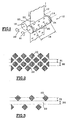
- FIG. 1 shows a device 10 in which a sheet of paper 12 is marked by passage between two cylinders 14, 16 of parallel axes A1 and A2 which rotate synchronously in opposite directions one with respect to the other around their respective axis.
- the sheet of paper 12 can be replaced by two sheets of paper, and their tightening will then not only aim to mark them but also to make them united. Marking (in the case of embossing) can also increase the absorbency of the paper. In all cases, we will seek to obtain the most aesthetic marking possible.
- the cylindrical surface 22 of one of the cylinders 14 is engraved so as to present a tightening band 18 which comprises a plurality of elements in relief 20.
- the second cylinder 16 called a counter-cylinder, has a smooth cylindrical surface 23.
- This contact zone also designated by the term "nip" is not limited to a straight line generator but is in the form of an axial strip having a certain dimension in the circumferential direction of the cylinders 14, 16 which is also the direction of travel of the sheet of paper 12.
- This contact area varies in particular depending on the nature of the materials constituting the cylinders 14, 16, their diameter and their spacing.
- the engraved cylinder 14 also comprises, on its cylindrical surface 22, two strips of load compensation 24 which are arranged here each at one end axial of the engraved cylinder 14, on either side of the clamping band 18, at outside the area of the cylinder 14 which is opposite the sheet of paper 12.
- FIG. 4 shows in relief the elements in relief of the cylinder surface 14.
- the elements in relief 20 are formed of diamonds or triangles. These are geometric shapes simple but the invention can of course be carried out for reasons of more complex and more ornamental form.
- the elements in relief 20 can for example be produced in the form of a series of points, which decreases the active surface of the tightening band 18 which is truly intended to come into contact with the counter-cylinder 16.
- a load compensation band an area elements in relief provided to compensate for variations in effort driven by the active surface of the clamping band; this area can be made up of independent relief elements (small picot-like elements) arranged discontinuously or alternatively be in the form of a strip keep on going.
- a strip of load compensation 24 is arranged on each side of the strip of marking 18 but, as shown in FIG. 5, one can plan to have only one load compensation strip 24 to one of the axial ends of the cylinder 14, this strip then being more great width.
- Each load compensation strip 24 is therefore intended to come to bear against the cylindrical surface 23 of the counter-cylinder 16, without through the sheet of paper 12 in the embodiment illustrated in Figure 1 and through the sheet of paper in other cases as developed further in the description.
- the active surface load compensating strip 24 corresponds to the part of the strip 24 which is included in the contact zone of the two cylinders or "nip".
- the active surface of the load compensation strip 24 is upgradeable. It varies in direction reverse of the active surface of the clamping band 18 for the same area of contact.
- the variation of the instantaneous active surfaces successive corresponding to the clamping band 18 and the band of load compensation 24 is substantially zero during rotation full of cylinders.
- the interaction force between the two cylinders 14, 16 is substantially constant, which is favorable for good resistance over time cylinders and the entire device.
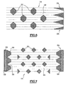
- the load compensation strip 24 has a first edge 28 which, when developed, is rectilinear, and a second non-rectilinear edge 30 whose profile determines the width of the compensation band charge 24.
- the compensation band load 24 is delimited by two non-straight edges.
- the cylinder circumference is analyzed by successive measurement areas. These zones may correspond in value to a “nip”. But, the bigger the area the finer the measurement, the more the load compensation band accuracy and less the variations in load are important. Therefore, the measurement area is preferably less than "nip”.
- the width of the strip of load compensation 24 may, in some places, be zero. This is produced when, in a contact zone considered, the active surface of the tightening band 18 reaches a maximum value.
- the load compensation strip 24 has a tread area 26 of constant width which in a way constitutes a minimal surface of interaction between the two cylinders 14, 16.
- the rolling zone 26 is for example provided in the center of this strip 24.
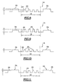
- Figures 8 to 10 show three diagrams illustrating schematically the position of the raised elements of the strip of tightening 18 relative to those of the load compensating strip 24.
- the height elements in relief of the load compensation strip 24 is greater than the height of the raised elements 20 of the tightening band 18.
- the height of the raised elements 20 of the load compensation strip 24 is less than the height of relief elements 20 of the tightening band 18, while, in FIG. 10, the case where the height of the elements in relief of the strip of load compensation 24 is substantially identical to the height of the relief elements of the tightening band 18.
- Figure 11 a diagram which illustrates the case in which the rolling zone 26 is arranged radially more towards inside as the rest of the load compensation strip 24.
- the rolling zone 26 can just as easily be arranged radially at the same level or more outward than the rest of the load compensation strip 24.
- the strip of load compensation 24 and the clamping band 18 are both carried by the same cylinder 14. This is particularly advantageous when the second cylinder 16 is smooth because only one of the two cylinders must be engraved, which makes it possible to carry out the invention without significant additional cost. However, there is nothing to prevent the two bands 18 and 24 from being each carried by one of the cylinders 14, 16. In the case where the strip of load compensation is not located on the cylinder with the relief elements of the tightening band, it is necessary to provide a good angular adjustment between the two cylinders to be able to wedge the strip load compensation with the distribution of the relief elements of the tightening band. Similarly, the rolling area can be carried by the second cylinder 16.
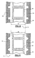
- Figures 12 and 13 illustrate particular embodiments of the device according to the invention, intended for marking the edges of absorbent paper products that are cut into formats. These products are for example napkins or handkerchiefs, Disposable.
- the clamping band 18 of the cylinder 14 comprises zones of border 32 comprising elements in relief intended to mark absorbent paper products made up of at least two folds and to bind these two folds at the edges or peripheral areas of the products in formats.
- a load compensation strip 24 is arranged on the side and on the other side of the tightening band.
- Figures 12 and 13 illustrate two forms possible geometries for load compensation strip 24.
- the load compensation strip 24 also includes a rolling area 26.
- the load compensation strip 24 is arranged in outside of the tightening band 18 of the cylinder 14 opposite which passes the sheet of paper 12 so that the compensation strip of charge 24 does not leave traces on the paper.
- the sheet of paper 12 is intended for the manufacture of paper articles which are of such a dimension that the sheet of paper 12 has drop zones on either side of a useful area of the sheet 12.
- the strip or strips of load compensation 24 can then be provided at least in part, in these drop zones.
- the raised elements of the load compensation strip 24 is sufficiently aesthetic to be able to be kept on the end product of the paper article.
- the compensation band of load 24 is arranged on the cylinder 14 so as to be at least partially in contact with the sheet of paper 12, which will have consequence that the trace of the load compensation strip 24 will be reproduced at least partially on the sheet of paper 12 thus forming additional marking.
- the band of load compensation of elements in relief similar but not identical (for example of different size) to those of the strip of tightening, which we will adapt.
- Figures 15, 16 and 17 illustrate different modes of definition a partial compensation strip that can be used instead of the theoretical compensation band shown in Figure 14 which is moreover of the type delimited by two edges formed by a broken line.
- the strip of theoretical load compensation has been clipped, i.e. all portions of the theoretical strip whose width exceeds a width maximum available are reduced to this so-called maximum width.
- the width of the strip Theoretical load compensation has been reduced by a constant factor of so that the maximum width of the partial compensation strip does not not exceed the maximum width available.
- FIG. 17 shows a third mode of realization of a partial compensation band whose shape is not directly from that of the theoretical band but which allows despite all to decrease the variation of the forces transmitted between the two cylinders 14, 16.
- the shape of the strip load compensation can be obtained from the theoretical form at using a mathematical function.
- the two cylinders of the device according to the invention can be made of the same material or of two different materials. At least one of them is engraved. Both can be made of non-deformable material such as steel or one of non-deformable material and the other of material deformable, for example rubber.
- Each of the cylinders can be made of a single material or several materials.
- the engraved cylinder consists of a part central for engraving the relief elements of the tightening band, made for example of steel, of one or more lateral parts possibly made of another material for the strip load compensation and possibly one or more others parts arranged laterally to the load compensation strips for the rolling area. These other parts can be done in the material of the load compensation bands or in another material. Materials for the load compensation band and for the other parts are non-deformable, identical or different.
- the counter-cylinder comprises a central part produced by rubber example for the raised elements of the band for clamping the engraved cylinder, one or more lateral parts for the with respect to the load compensation strip and, where appropriate, the rolling area. These lateral parts coming into contact with the strip of load and, where applicable, rolling area compensation, can be made of rubber or from one or more other materials.
- the lateral parts corresponding respectively to the strip load compensation and rolling area can be performed in the same or different material.
- the engraved and counterpart cylinders if they are made in the same material, may also have surface treatment areas different.
- the methods using the devices according to the invention can independently lead to deformation of a sheet of paper or the association of several sheets of paper or simultaneously the deformation and association of several sheets, according to characteristics of the process and the installation comprising the devices according to the invention.
- the method implements a device according to the invention in which the sheets are clamped between the two cylinders at the level of the tightening band, with or without adhesive.
- two sheets can be embossed by using two independent or dependent devices, then be associated by setting up work of a third device.
- this third device has at least one cylinder in common (the engraved cylinder) with one of the two first devices used for embossing.
- the first two devices are dependent (have a cylinder in common) and each emboss a sheet; the association is produced by a device consisting of two cylinders each belonging first and second devices respectively.
- the invention also relates to a method of applying an additive such than an adhesive, lotion or ink, on a sheet of paper or nonwoven comprising the use of a device according to the invention.
- the invention thus makes it possible to obtain articles of paper or of nonwoven marked or embossed in a variety of patterns. It provides also products comprising several integral sheets or associated with each other.
Landscapes
- Health & Medical Sciences (AREA)
- Engineering & Computer Science (AREA)
- Life Sciences & Earth Sciences (AREA)
- Hematology (AREA)
- General Health & Medical Sciences (AREA)
- Anesthesiology (AREA)
- Biomedical Technology (AREA)
- Heart & Thoracic Surgery (AREA)
- Biophysics (AREA)
- Animal Behavior & Ethology (AREA)
- Pulmonology (AREA)
- Public Health (AREA)
- Veterinary Medicine (AREA)
- Mechanical Engineering (AREA)
- Treatment Of Fiber Materials (AREA)
- Paper (AREA)
- Machines For Manufacturing Corrugated Board In Mechanical Paper-Making Processes (AREA)
- Absorbent Articles And Supports Therefor (AREA)
- Folding Of Thin Sheet-Like Materials, Special Discharging Devices, And Others (AREA)
Claims (30)
- Vorrichtung zum Prägen von mindestens einem Blatt Papier oder Vliesstoff (12), die zwei Walzen (14, 16) umfasst, die einander beinahe berühren, wobei mindestens eine Walze auf ihrer Oberfläche, in einem Bereich, der dafür gedacht ist, mit diesem Blatt (12) in Berührung zu stehen, ein Prägeband (18) umfasst, das erste hervorstehende Bestandteile aufweist, wobei durch das Wechselwirken der zwei Walzen mit oder ohne Blatt während des Drehens der Walzen eine wirksame Fläche beschrieben ist, dadurch gekennzeichnet, dass mindestens eine (14) der Walzen auf ihrer Oberfläche, in einem Bereich, der dafür gedacht ist, mit der anderen Walze über das Blatt oder ohne das Blatt in Berührung zu stehen, ein. Belastungsausgleichsband (24) umfasst, das zweite hervorstehende Bestandteile aufweist und so gewählt ist, dass die Veränderung der aufeinander folgenden momentanen wirksamen Flächen, die dem Prägeband (18) und dem Belastungsausgleichsband (24) entsprechen, geringer ist als die Veränderung der aufeinander folgenden momentanen wirksamen Flächen, die nur dem Prägeband (18) entsprechen.
- Vorrichtung nach Anspruch 1, dadurch gekennzeichnet, dass die Veränderung der aufeinander folgenden momentanen wirksamen Flächen, die dem Prägeband (18) und dem Belastungsausgleichsband (24) entsprechen, ungefähr null ist.
- Vorrichtung nach einem der vorhergehenden Ansprüche, dadurch gekennzeichnet, dass sich die Breite der wirksamen Fläche, die nur dem Belastungsausgleichsband (24) entspricht, entlang dem Umfang der Walze ändert, auf der dieses Band erzeugt wurde, in Abhängigkeit von der wirksamen Fläche, die nur dem Prägeband (18) entspricht.
- Vorrichtung nach einem der vorhergehenden Ansprüche, dadurch gekennzeichnet, dass die zuvor genannten Walzen gegenläufig sind.
- Vorrichtung nach einem der vorhergehenden Ansprüche, dadurch gekennzeichnet, dass die ersten hervorstehenden Bestandteile des Prägebands (18) vollkommen übereinstimmen mit oder verschieden sind von den zweiten hervorstehenden Bestandteilen des Belastungsausgleichsbands (24).
- Vorrichtung nach einem der vorhergehenden Ansprüche, dadurch gekennzeichnet, dass das Belastungsausgleichsband (24) auf einer Walze (14) außerhalb des Prägebands (18) angeordnet ist.
- Vorrichtung nach einem der Ansprüche 1 bis 5, dadurch gekennzeichnet, dass die zweiten hervorstehenden Bestandteile des Belastungsausgleichsbands verschieden sind von den ersten hervorstehenden Bestandteilen des Prägebands und dadurch gekennzeichnet, dass sich das Belastungsausgleichsband (24) zumindest teilweise mit dem Prägeband überschneidet.
- Vorrichtung nach einem der vorhergehenden Ansprüche, dadurch gekennzeichnet, dass sich auf mindestens einer Walze (14) mindestens ein Prägeband (18) und mindestens ein Belastungsausgleichsband (24) befindet.
- Vorrichtung nach Anspruch 8, dadurch gekennzeichnet, dass die Höhe der hervorstehenden Bestandteile des Belastungsausgleichsbands (24) ungefähr der Höhe der hervorstehenden Bestandteile des Prägebands (18) entspricht.
- Vorrichtung nach Anspruch 8, dadurch gekennzeichnet, dass die Höhe der hervorstehenden Bestandteile des Belastungsausgleichsbands (24) größer ist als die Höhe der hervorstehenden Bestandteile des Prägebands (18).
- Vorrichtung nach Anspruch 8, dadurch gekennzeichnet, dass die Höhe der hervorstehenden Bestandteile des Belastungsausgleichsbands (24) geringer ist als die Höhe der hervorstehenden Bestandteile des Prägebands (18).
- Vorrichtung nach einem der vorhergehenden Ansprüche, dadurch gekennzeichnet, dass das Ausgleichsband (24) einen Laufbereich (26) umfasst, der eine minimale Breite der wirksamen Fläche des Belastungsausgleichsbands (24) bestimmt.
- Vorrichtung nach Anspruch 12, dadurch gekennzeichnet, dass der Laufbereich (26) des Belastungsausgleichsbands (24) vom Mittelpunkt ausgehend auf gleicher Höhe wie das übrige Belastungsausgleichsband (24) angeordnet ist.
- Vorrichtung nach Anspruch 12, dadurch gekennzeichnet, dass der Laufbereich (26) des Ausgleichsbands (24) vom Mittelpunkt ausgehend nach außen im Verhältnis zum übrigen Belastungsausgleichsband (24) angeordnet ist.
- Vorrichtung nach Anspruch 12, dadurch gekennzeichnet, dass der Laufbereich (26) des Belastungsausgleichsbands (24) vom Mittelpunkt ausgehend nach innen im Verhältnis zum übrigen Belastungsausgleichsband (24) angeordnet ist.
- Vorrichtung nach einem der vorhergehenden Ansprüche, dadurch gekennzeichnet, dass auf der gleichen Walze mehrere Belastungsausgleichsbänder (24) vorgesehen sind.
- Vorrichtung nach Anspruch 16 in Verbindung mit einem der Ansprüche 12 bis 15, dadurch gekennzeichnet, dass jedes Belastungsausgleichsband (24) einen Laufbereich (26) umfasst.
- Vorrichtung nach einem der vorhergehenden Ansprüche, dadurch gekennzeichnet, dass beide Walzen aus einem nicht verformbaren Werkstoff bestehen.
- Vorrichtung nach einem der Ansprüche 1 bis 17, dadurch gekennzeichnet, dass eine Walze aus einem nicht verformbaren Werkstoff und die andere aus einem verformbaren Werkstoff besteht.
- Walze zum Prägen von einem Blatt Papier oder Vliesstoff, dadurch gekennzeichnet, dass sie Teil der Vorrichtung nach einem der vorhergehenden Ansprüche ist und dadurch gekennzeichnet, dass sie ein Belastungsausgleichsband (24) umfasst.
- Einrichtung, die mindestens eine Vorrichtung zum Prägen nach einem der Ansprüche 1 bis 19 umfasst.
- Einrichtung nach Anspruch 21, dadurch gekennzeichnet, dass sie mindestens zwei Vorrichtungen nach einem der Ansprüche 1 bis 19 umfasst, wobei die Vorrichtungen unabhängig voneinander sind.
- Einrichtung nach Anspruch 21, dadurch gekennzeichnet, dass sie mindestens zwei Vorrichtungen nach einem der Ansprüche 1 bis 19 umfasst, wobei mindestens zwei der Vorrichtungen eine gemeinsame Walze aufweisen.
- Verfahren zum Verbinden von mindestens zwei Blättern Papier oder Vliesstoff, dadurch gekennzeichnet, dass es den Einsatz einer Vorrichtung nach einem der Ansprüche 1 bis 19 umfasst, in der die Blätter zwischen den beiden Walzen auf Höhe des Prägebands (18) geprägt werden, mit oder ohne Zugabe von Klebstoff.
- Verfahren zum Kennzeichnen von mindestens einem Blatt Papier oder Vliesstoff, dadurch gekennzeichnet, dass es den Einsatz einer Vorrichtung nach einem der Ansprüche 1 bis 19 umfasst, in dem das Prägeband (18) auf dem Papier oder Vliesstoff ein Muster durch Verformen des Blatts erzeugt, das zwischen den beiden Walzen geprägt wird.
- Verfahren nach Anspruch 25, dadurch gekennzeichnet, dass es sich um eine Gaufrage handelt.
- Verfahren nach Anspruch 26, dadurch gekennzeichnet, dass zwei Blätter Papier oder Vliesstoff von zwei eigenständigen bzw. abhängigen Vorrichtungen nach einem der Ansprüche 1 bis 19 gaufriert und dann durch den Einsatz einer dritten Vorrichtung nach einem der Ansprüche 1 bis 19 verbunden sind.
- Verfahren nach Anspruch 27, dadurch gekennzeichnet, dass die dritte Vorrichtung mindestens eine gravierte Walze aufweist, die sie mit einer der beiden zuvor genannten Vorrichtungen gemein hat, die für die Gaufrage eingesetzt werden.
- Verfahren zum Aufbringen eines Zusatzstoffs wie einem Klebstoff, einer Lotion oder Tinte auf einem Blatt Papier oder Vliesstoff, dadurch gekennzeichnet, dass es den Einsatz einer Vorrichtung nach einem der Ansprüche 1 bis 19 umfasst.
- Verfahren zum Herstellen von Produkten aus Zellstoffwatte, die mindestens zwei Blätter umfassen, dadurch gekennzeichnet, dass die Blätter fest miteinander verbunden werden durch ein Kennzeichnungs-, Gaufrageoder Verbindungsverfahren nach einem der Ansprüche 24 bis 28.
Priority Applications (9)
| Application Number | Priority Date | Filing Date | Title |
|---|---|---|---|
| PT00401191T PT1151852E (pt) | 2000-04-28 | 2000-04-28 | Dispositivo e processo para o aperto de papel ou material nao tecido, e produto fabricado |
| EP00401191A EP1151852B1 (de) | 2000-04-28 | 2000-04-28 | Vorrichtung und Verfahren zum Prägen von Papier oder Vliesstoff, sowie das hergestellte Produkt |
| DE60016175T DE60016175T2 (de) | 2000-04-28 | 2000-04-28 | Vorrichtung und Verfahren zum Prägen von Papier oder Vliesstoff, sowie das hergestellte Produkt |
| AT00401191T ATE283166T1 (de) | 2000-04-28 | 2000-04-28 | Vorrichtung und verfahren zum prägen von papier oder vliesstoff, sowie das hergestellte produkt |
| DK00401191T DK1151852T3 (da) | 2000-04-28 | 2000-04-28 | Anordning og fremgangsmåde til klemning af papir eller nonwoven, og fremstillet produkt |
| ES00401191T ES2231135T3 (es) | 2000-04-28 | 2000-04-28 | Dispositivo y procedimiento para el apriete de papel o no tejido, y articulo fabricado. |
| CA002344261A CA2344261C (fr) | 2000-04-28 | 2001-04-18 | Dispositif, cylindre et installation pour le serrage d'au moins une feuille de papier ou nontisse, procedes mettant en oeuvre un tel dispositif et article fabrique selon ces procedes |
| US09/839,406 US6475346B2 (en) | 2000-04-28 | 2001-04-23 | Apparatus to clamp at least one non-woven or paper sheet, methods implementing such apparatus, and article made by such methods |
| TR2001/01063A TR200101063A2 (tr) | 2000-04-28 | 2001-04-26 | En az bir kağıdı veya dokumasızı sıkmak için tertibat, silindir ve tesis, bu tür bir tertibat kullanan yöntemler ve bu yöntemlere göre üretilen ürün |
Applications Claiming Priority (1)
| Application Number | Priority Date | Filing Date | Title |
|---|---|---|---|
| EP00401191A EP1151852B1 (de) | 2000-04-28 | 2000-04-28 | Vorrichtung und Verfahren zum Prägen von Papier oder Vliesstoff, sowie das hergestellte Produkt |
Publications (2)
| Publication Number | Publication Date |
|---|---|
| EP1151852A1 EP1151852A1 (de) | 2001-11-07 |
| EP1151852B1 true EP1151852B1 (de) | 2004-11-24 |
Family
ID=8173662
Family Applications (1)
| Application Number | Title | Priority Date | Filing Date |
|---|---|---|---|
| EP00401191A Expired - Lifetime EP1151852B1 (de) | 2000-04-28 | 2000-04-28 | Vorrichtung und Verfahren zum Prägen von Papier oder Vliesstoff, sowie das hergestellte Produkt |
Country Status (9)
| Country | Link |
|---|---|
| US (1) | US6475346B2 (de) |
| EP (1) | EP1151852B1 (de) |
| AT (1) | ATE283166T1 (de) |
| CA (1) | CA2344261C (de) |
| DE (1) | DE60016175T2 (de) |
| DK (1) | DK1151852T3 (de) |
| ES (1) | ES2231135T3 (de) |
| PT (1) | PT1151852E (de) |
| TR (1) | TR200101063A2 (de) |
Families Citing this family (9)
| Publication number | Priority date | Publication date | Assignee | Title |
|---|---|---|---|---|
| US7056404B2 (en) * | 1998-11-25 | 2006-06-06 | The Procter & Gamble Company | Methods of bonding materials, especially materials used in absorbent articles |
| ITFI20020061A1 (it) * | 2002-04-12 | 2003-10-13 | Perini Fabio Spa | Dispositivo e metodo di accoppiamento di veli per la formazione di manufatti in foglio e manufatti cosi'ottenuti |
| DE102005056109A1 (de) * | 2005-11-23 | 2007-05-24 | WINKLER + DüNNEBIER AG | Prägewalze und Verfahren zum Erzeugen eines Prägemusters in einer Materialbahn oder in einem Zuschnitt |
| US8739728B2 (en) * | 2011-04-07 | 2014-06-03 | Dynamic Micro Systems, Semiconductor Equipment Gmbh | Methods and apparatuses for roll-on coating |
| MX2014014334A (es) * | 2012-06-08 | 2015-02-12 | Procter & Gamble | Estructuras fibrosas grabadas. |
| US20140346704A1 (en) * | 2013-05-22 | 2014-11-27 | The Procter & Gamble Company | Method for producing an absorbent paper product having visual elements |
| US20140349056A1 (en) * | 2013-05-22 | 2014-11-27 | The Procter & Gamble Company | Absorbent paper product having visual elements |
| US11413804B2 (en) * | 2018-02-06 | 2022-08-16 | Xerox Corporation | Method and apparatus for embossing a substrate |
| BR112020022071A2 (pt) | 2018-05-29 | 2021-02-02 | José Antonio Logiodice | aperfeiçoamento em conjunto gofrador para processamento de papel |
Family Cites Families (8)
| Publication number | Priority date | Publication date | Assignee | Title |
|---|---|---|---|---|
| US3893795A (en) * | 1970-08-20 | 1975-07-08 | Rowland Dev Corp | Embossing rolls with areas of differential hardness |
| GB1474101A (en) * | 1974-04-26 | 1977-05-18 | Ici Ltd | Non-woven fabrics |
| US4803032A (en) * | 1983-05-17 | 1989-02-07 | James River-Norwalk, Inc. | Method of spot embossing a fibrous sheet |
| IT1225324B (it) * | 1988-11-23 | 1990-11-06 | Perini Finanziaria Spa | Macchina per la trasformazione della carta con cilindri goffratori cooperanti per l'accoppiamento punta-punta di due nastri di carta da essi goffrati |
| JPH077147Y2 (ja) * | 1989-06-05 | 1995-02-22 | 株式会社磯輪鉄工所 | 片面段ボール製造装置 |
| IT1278802B1 (it) * | 1995-12-05 | 1997-11-28 | Perini Fabio Spa | Gruppo goffratore-laminatore, con cilindri a contatti distribuiti e relativo metodo di goffratura |
| US6170393B1 (en) * | 1998-05-21 | 2001-01-09 | The Procter & Gamble Company | Compliant embosser assembly |
| US6251207B1 (en) * | 1998-12-31 | 2001-06-26 | Kimberly-Clark Worldwide, Inc. | Embossing and laminating irregular bonding patterns |
-
2000
- 2000-04-28 AT AT00401191T patent/ATE283166T1/de active
- 2000-04-28 ES ES00401191T patent/ES2231135T3/es not_active Expired - Lifetime
- 2000-04-28 DK DK00401191T patent/DK1151852T3/da active
- 2000-04-28 DE DE60016175T patent/DE60016175T2/de not_active Expired - Lifetime
- 2000-04-28 EP EP00401191A patent/EP1151852B1/de not_active Expired - Lifetime
- 2000-04-28 PT PT00401191T patent/PT1151852E/pt unknown
-
2001
- 2001-04-18 CA CA002344261A patent/CA2344261C/fr not_active Expired - Fee Related
- 2001-04-23 US US09/839,406 patent/US6475346B2/en not_active Expired - Lifetime
- 2001-04-26 TR TR2001/01063A patent/TR200101063A2/xx unknown
Also Published As
| Publication number | Publication date |
|---|---|
| US20020060032A1 (en) | 2002-05-23 |
| PT1151852E (pt) | 2005-04-29 |
| EP1151852A1 (de) | 2001-11-07 |
| CA2344261C (fr) | 2009-09-15 |
| ES2231135T3 (es) | 2005-05-16 |
| DE60016175D1 (de) | 2004-12-30 |
| ATE283166T1 (de) | 2004-12-15 |
| DE60016175T2 (de) | 2005-12-15 |
| TR200101063A3 (tr) | 2001-11-21 |
| US6475346B2 (en) | 2002-11-05 |
| TR200101063A2 (tr) | 2001-11-21 |
| CA2344261A1 (fr) | 2001-10-28 |
| DK1151852T3 (da) | 2005-03-21 |
Similar Documents
| Publication | Publication Date | Title |
|---|---|---|
| EP0426548B1 (de) | Mehrschichtiges absorbierendes Papier | |
| EP0679122B1 (de) | Verfahren zur herstellung einer prägefolie aus einer oder mehreren schichten | |
| EP0572503B1 (de) | Verfahren zum prägen und kaschieren von papier, sowie erhaltenes produkt | |
| EP1084300B1 (de) | Dreilagiges saugfähiges papierprodukt und verfahren zu seiner herstellung | |
| EP0935021B1 (de) | Saugfähiges Haushaltpapier | |
| CA2193088C (fr) | Feuille multicouche de papier absorbant, son procede de fabrication | |
| EP1325982B1 (de) | Geprägte Papierbahn | |
| EP1047546B1 (de) | Geprägte absorbierende papierbahn, herstellungsverfahren und vorrichtung zu dessen herstellung | |
| EP1270196B1 (de) | Verfahren zur Herstellung von geprägtem Papier und Prägezylinder | |
| EP1209289A1 (de) | Gekreppte, saugfähige Papierbahn, Kreppwalze, und Verfahren zur Herstellung solcher Papierbahn | |
| EP1151852B1 (de) | Vorrichtung und Verfahren zum Prägen von Papier oder Vliesstoff, sowie das hergestellte Produkt | |
| EP1391174B1 (de) | Rolle aus Zellstoffwatteblättern und Verfahren zu ihrer Herstellung | |
| EP1081284B1 (de) | Saugfähiges, mindestens dreilagiges Papierprodukt und Verfahren zu seiner Herstellung | |
| EP1670991B1 (de) | Blatt aus saugfähigem papier mit verbessertem relief | |
| EP2437932B1 (de) | Geprägtes saugfähiges papier mit gemischter struktur | |
| EP2069136B1 (de) | Verfahren und anlage zur kombination von papierlagen zwecks formung eines saugfähigen papiers | |
| EP1285133A2 (de) | Saugfähiges papierprodukt mit unsymmetrischer struktur | |
| FR2751267A1 (fr) | Materiau d'approvisionnement de machine de fabrication de produit de rembourrage | |
| WO2008037877A2 (fr) | Procede et ensemble de fabrication d'une feuille absorbante, et feuille absorbante obtenue | |
| EP0828602B1 (de) | Verfahren zum herstellen von absorbierenden structuren | |
| CA2406577C (fr) | Feuille de papier absorbant crepee et gaufree, cylindre de gaufrage d'une telle feuille et procede de gaufrage | |
| FR2766125A1 (fr) | Procede de fabrication de produits cellulosiques fibreux, tels que notamment des mouchoirs ou des serviettes | |
| CA2202166C (fr) | Papier absorbant gaufre a motifs combines | |
| CA2223015C (fr) | Procede de fabrication d'une structure absorbante | |
| EP1584458A1 (de) | Verfahren zum Herstellen eines mehrlagigen Zellulosefaserprodukts |
Legal Events
| Date | Code | Title | Description |
|---|---|---|---|
| PUAI | Public reference made under article 153(3) epc to a published international application that has entered the european phase |
Free format text: ORIGINAL CODE: 0009012 |
|
| AK | Designated contracting states |
Kind code of ref document: A1 Designated state(s): AT BE CH CY DE DK ES FI FR GB GR IE IT LI LU MC NL PT SE |
|
| AX | Request for extension of the european patent |
Free format text: AL;LT;LV;MK;RO;SI |
|
| 17P | Request for examination filed |
Effective date: 20020507 |
|
| AKX | Designation fees paid |
Free format text: AT BE CH CY DE DK ES FI FR GB GR IE IT LI LU MC NL PT SE |
|
| 17Q | First examination report despatched |
Effective date: 20030911 |
|
| GRAP | Despatch of communication of intention to grant a patent |
Free format text: ORIGINAL CODE: EPIDOSNIGR1 |
|
| GRAS | Grant fee paid |
Free format text: ORIGINAL CODE: EPIDOSNIGR3 |
|
| GRAA | (expected) grant |
Free format text: ORIGINAL CODE: 0009210 |
|
| AK | Designated contracting states |
Kind code of ref document: B1 Designated state(s): AT BE CH CY DE DK ES FI FR GB GR IE IT LI LU MC NL PT SE |
|
| REG | Reference to a national code |
Ref country code: GB Ref legal event code: FG4D Free format text: NOT ENGLISH |
|
| REG | Reference to a national code |
Ref country code: CH Ref legal event code: EP |
|
| REF | Corresponds to: |
Ref document number: 60016175 Country of ref document: DE Date of ref document: 20041230 Kind code of ref document: P |
|
| REG | Reference to a national code |
Ref country code: IE Ref legal event code: FG4D Free format text: FRENCH |
|
| REG | Reference to a national code |
Ref country code: CH Ref legal event code: NV Representative=s name: MICHELI & CIE INGENIEURS-CONSEILS |
|
| REG | Reference to a national code |
Ref country code: SE Ref legal event code: TRGR |
|
| REG | Reference to a national code |
Ref country code: DK Ref legal event code: T3 |
|
| GBT | Gb: translation of ep patent filed (gb section 77(6)(a)/1977) |
Effective date: 20050302 |
|
| REG | Reference to a national code |
Ref country code: GR Ref legal event code: EP Ref document number: 20050400332 Country of ref document: GR |
|
| PG25 | Lapsed in a contracting state [announced via postgrant information from national office to epo] |
Ref country code: LU Free format text: LAPSE BECAUSE OF NON-PAYMENT OF DUE FEES Effective date: 20050428 Ref country code: CY Free format text: LAPSE BECAUSE OF FAILURE TO SUBMIT A TRANSLATION OF THE DESCRIPTION OR TO PAY THE FEE WITHIN THE PRESCRIBED TIME-LIMIT Effective date: 20050428 |
|
| REG | Reference to a national code |
Ref country code: PT Ref legal event code: SC4A Free format text: AVAILABILITY OF NATIONAL TRANSLATION Effective date: 20050214 |
|
| PG25 | Lapsed in a contracting state [announced via postgrant information from national office to epo] |
Ref country code: MC Free format text: LAPSE BECAUSE OF NON-PAYMENT OF DUE FEES Effective date: 20050430 |
|
| REG | Reference to a national code |
Ref country code: ES Ref legal event code: FG2A Ref document number: 2231135 Country of ref document: ES Kind code of ref document: T3 |
|
| PLBE | No opposition filed within time limit |
Free format text: ORIGINAL CODE: 0009261 |
|
| STAA | Information on the status of an ep patent application or granted ep patent |
Free format text: STATUS: NO OPPOSITION FILED WITHIN TIME LIMIT |
|
| 26N | No opposition filed |
Effective date: 20050825 |
|
| PGFP | Annual fee paid to national office [announced via postgrant information from national office to epo] |
Ref country code: DK Payment date: 20140324 Year of fee payment: 15 Ref country code: NL Payment date: 20140320 Year of fee payment: 15 Ref country code: IE Payment date: 20140325 Year of fee payment: 15 Ref country code: FI Payment date: 20140324 Year of fee payment: 15 Ref country code: SE Payment date: 20140326 Year of fee payment: 15 Ref country code: CH Payment date: 20140326 Year of fee payment: 15 |
|
| PGFP | Annual fee paid to national office [announced via postgrant information from national office to epo] |
Ref country code: GR Payment date: 20140326 Year of fee payment: 15 |
|
| PGFP | Annual fee paid to national office [announced via postgrant information from national office to epo] |
Ref country code: BE Payment date: 20140328 Year of fee payment: 15 |
|
| PGFP | Annual fee paid to national office [announced via postgrant information from national office to epo] |
Ref country code: AT Payment date: 20140324 Year of fee payment: 15 Ref country code: ES Payment date: 20140404 Year of fee payment: 15 Ref country code: PT Payment date: 20140403 Year of fee payment: 15 |
|
| REG | Reference to a national code |
Ref country code: PT Ref legal event code: MM4A Free format text: LAPSE DUE TO NON-PAYMENT OF FEES Effective date: 20151028 |
|
| REG | Reference to a national code |
Ref country code: DK Ref legal event code: EBP Effective date: 20150430 |
|
| REG | Reference to a national code |
Ref country code: CH Ref legal event code: PL |
|
| REG | Reference to a national code |
Ref country code: SE Ref legal event code: EUG Ref country code: AT Ref legal event code: MM01 Ref document number: 283166 Country of ref document: AT Kind code of ref document: T Effective date: 20150428 |
|
| REG | Reference to a national code |
Ref country code: NL Ref legal event code: MM Effective date: 20150501 |
|
| REG | Reference to a national code |
Ref country code: IE Ref legal event code: MM4A |
|
| PG25 | Lapsed in a contracting state [announced via postgrant information from national office to epo] |
Ref country code: GR Free format text: LAPSE BECAUSE OF NON-PAYMENT OF DUE FEES Effective date: 20151106 Ref country code: LI Free format text: LAPSE BECAUSE OF NON-PAYMENT OF DUE FEES Effective date: 20150430 Ref country code: FI Free format text: LAPSE BECAUSE OF NON-PAYMENT OF DUE FEES Effective date: 20150428 Ref country code: CH Free format text: LAPSE BECAUSE OF NON-PAYMENT OF DUE FEES Effective date: 20150430 |
|
| REG | Reference to a national code |
Ref country code: GR Ref legal event code: ML Ref document number: 20050400332 Country of ref document: GR Effective date: 20151106 |
|
| PG25 | Lapsed in a contracting state [announced via postgrant information from national office to epo] |
Ref country code: PT Free format text: LAPSE BECAUSE OF NON-PAYMENT OF DUE FEES Effective date: 20151028 Ref country code: SE Free format text: LAPSE BECAUSE OF NON-PAYMENT OF DUE FEES Effective date: 20150429 Ref country code: AT Free format text: LAPSE BECAUSE OF NON-PAYMENT OF DUE FEES Effective date: 20150428 |
|
| REG | Reference to a national code |
Ref country code: FR Ref legal event code: PLFP Year of fee payment: 17 |
|
| PG25 | Lapsed in a contracting state [announced via postgrant information from national office to epo] |
Ref country code: NL Free format text: LAPSE BECAUSE OF NON-PAYMENT OF DUE FEES Effective date: 20150501 |
|
| PG25 | Lapsed in a contracting state [announced via postgrant information from national office to epo] |
Ref country code: DK Free format text: LAPSE BECAUSE OF NON-PAYMENT OF DUE FEES Effective date: 20150430 Ref country code: IE Free format text: LAPSE BECAUSE OF NON-PAYMENT OF DUE FEES Effective date: 20150428 |
|
| REG | Reference to a national code |
Ref country code: ES Ref legal event code: FD2A Effective date: 20160527 |
|
| PGFP | Annual fee paid to national office [announced via postgrant information from national office to epo] |
Ref country code: GB Payment date: 20160324 Year of fee payment: 17 Ref country code: FR Payment date: 20160323 Year of fee payment: 17 |
|
| PG25 | Lapsed in a contracting state [announced via postgrant information from national office to epo] |
Ref country code: ES Free format text: LAPSE BECAUSE OF NON-PAYMENT OF DUE FEES Effective date: 20150429 |
|
| PGFP | Annual fee paid to national office [announced via postgrant information from national office to epo] |
Ref country code: DE Payment date: 20160321 Year of fee payment: 17 |
|
| PGFP | Annual fee paid to national office [announced via postgrant information from national office to epo] |
Ref country code: IT Payment date: 20160324 Year of fee payment: 17 |
|
| PG25 | Lapsed in a contracting state [announced via postgrant information from national office to epo] |
Ref country code: BE Free format text: LAPSE BECAUSE OF NON-PAYMENT OF DUE FEES Effective date: 20150430 |
|
| REG | Reference to a national code |
Ref country code: DE Ref legal event code: R119 Ref document number: 60016175 Country of ref document: DE |
|
| GBPC | Gb: european patent ceased through non-payment of renewal fee |
Effective date: 20170428 |
|
| REG | Reference to a national code |
Ref country code: FR Ref legal event code: ST Effective date: 20171229 |
|
| PG25 | Lapsed in a contracting state [announced via postgrant information from national office to epo] |
Ref country code: FR Free format text: LAPSE BECAUSE OF NON-PAYMENT OF DUE FEES Effective date: 20170502 Ref country code: DE Free format text: LAPSE BECAUSE OF NON-PAYMENT OF DUE FEES Effective date: 20171103 |
|
| PG25 | Lapsed in a contracting state [announced via postgrant information from national office to epo] |
Ref country code: GB Free format text: LAPSE BECAUSE OF NON-PAYMENT OF DUE FEES Effective date: 20170428 |
|
| PG25 | Lapsed in a contracting state [announced via postgrant information from national office to epo] |
Ref country code: IT Free format text: LAPSE BECAUSE OF NON-PAYMENT OF DUE FEES Effective date: 20170428 |