EP1150394A2 - Lenkrad - Google Patents
Lenkrad Download PDFInfo
- Publication number
- EP1150394A2 EP1150394A2 EP01104469A EP01104469A EP1150394A2 EP 1150394 A2 EP1150394 A2 EP 1150394A2 EP 01104469 A EP01104469 A EP 01104469A EP 01104469 A EP01104469 A EP 01104469A EP 1150394 A2 EP1150394 A2 EP 1150394A2
- Authority
- EP
- European Patent Office
- Prior art keywords
- steering wheel
- connector
- attached
- complementary
- spring element
- Prior art date
- Legal status (The legal status is an assumption and is not a legal conclusion. Google has not performed a legal analysis and makes no representation as to the accuracy of the status listed.)
- Withdrawn
Links
- 230000000295 complement effect Effects 0.000 claims abstract description 17
- 238000003780 insertion Methods 0.000 claims abstract description 6
- 230000037431 insertion Effects 0.000 claims abstract description 6
- 238000005352 clarification Methods 0.000 description 1
- 230000001419 dependent effect Effects 0.000 description 1
- 230000001771 impaired effect Effects 0.000 description 1
- 230000013011 mating Effects 0.000 description 1
Images

Classifications
-
- H—ELECTRICITY
- H01—ELECTRIC ELEMENTS
- H01R—ELECTRICALLY-CONDUCTIVE CONNECTIONS; STRUCTURAL ASSOCIATIONS OF A PLURALITY OF MUTUALLY-INSULATED ELECTRICAL CONNECTING ELEMENTS; COUPLING DEVICES; CURRENT COLLECTORS
- H01R13/00—Details of coupling devices of the kinds covered by groups H01R12/70 or H01R24/00 - H01R33/00
- H01R13/62—Means for facilitating engagement or disengagement of coupling parts or for holding them in engagement
- H01R13/629—Additional means for facilitating engagement or disengagement of coupling parts, e.g. aligning or guiding means, levers, gas pressure electrical locking indicators, manufacturing tolerances
- H01R13/631—Additional means for facilitating engagement or disengagement of coupling parts, e.g. aligning or guiding means, levers, gas pressure electrical locking indicators, manufacturing tolerances for engagement only
- H01R13/6315—Additional means for facilitating engagement or disengagement of coupling parts, e.g. aligning or guiding means, levers, gas pressure electrical locking indicators, manufacturing tolerances for engagement only allowing relative movement between coupling parts, e.g. floating connection
-
- B—PERFORMING OPERATIONS; TRANSPORTING
- B60—VEHICLES IN GENERAL
- B60Q—ARRANGEMENT OF SIGNALLING OR LIGHTING DEVICES, THE MOUNTING OR SUPPORTING THEREOF OR CIRCUITS THEREFOR, FOR VEHICLES IN GENERAL
- B60Q5/00—Arrangement or adaptation of acoustic signal devices
- B60Q5/001—Switches therefor
- B60Q5/003—Switches therefor mounted on the steering wheel
-
- B—PERFORMING OPERATIONS; TRANSPORTING
- B60—VEHICLES IN GENERAL
- B60R—VEHICLES, VEHICLE FITTINGS, OR VEHICLE PARTS, NOT OTHERWISE PROVIDED FOR
- B60R21/00—Arrangements or fittings on vehicles for protecting or preventing injuries to occupants or pedestrians in case of accidents or other traffic risks
- B60R21/02—Occupant safety arrangements or fittings, e.g. crash pads
- B60R21/16—Inflatable occupant restraints or confinements designed to inflate upon impact or impending impact, e.g. air bags
- B60R21/20—Arrangements for storing inflatable members in their non-use or deflated condition; Arrangement or mounting of air bag modules or components
- B60R21/203—Arrangements for storing inflatable members in their non-use or deflated condition; Arrangement or mounting of air bag modules or components in steering wheels or steering columns
- B60R21/2035—Arrangements for storing inflatable members in their non-use or deflated condition; Arrangement or mounting of air bag modules or components in steering wheels or steering columns using modules containing inflator, bag and cover attachable to the steering wheel as a complete sub-unit
Definitions
- the invention relates to a steering wheel with a connector, the is intended to be inserted into a complementary connector to connect a component attached to the steering wheel.
- Such a steering wheel is from German utility model 299 17 129 known.
- the one from the connector on the steering wheel and the complementary one Connector that is attached to the vehicle, trained connector is used, for example, for the igniter of a gas generator to connect an airbag system.
- the connector on the steering wheel is designed so that it when mounting the steering wheel on Vehicle automatically inserted into the complementary connector becomes. Furthermore, the connector on the steering wheel can be moved slightly attached so that when the steering wheel turns Tolerance compensation is possible.
- the connector attached to the steering wheel and the complementary connector attached to the vehicle theoretically rotate around the same axis, namely the central axis the steering shaft; even slight tolerances lead to that the trajectories of the two connectors are not complete are concentric.
- the object of the invention is therefore a steering wheel type mentioned in that the free Movability of the connector on the steering wheel after assembly is guaranteed.
- a steering wheel of the type mentioned provided which is characterized in that a bistable Spring element is provided which extends from the steering wheel to Connector extends, the spring element a first stable Can take position in which it the connector in a Mounting position applied, and a second stable position can occupy the connector of the complementary Connector applied away, and that the connector in the direction of insertion is slidably attached to the steering wheel.
- the spring element snaps from the first when mounting the steering wheel on the vehicle stable position in the second stable position so that it is on the Connector exerts a force that acts during assembly Counteracts plug-in force. In this way the mechanical tension of the connector, which results from the insertion force, lifted, and the connector can run smoothly on the steering wheel be moved when it is rotated.
- a vehicle steering wheel 10 can be seen in FIG Steering shaft 12 is connected.
- the steering wheel has an airbag module 14 on, which essentially consists of an airbag 16 and a gas generator 18 exists.
- the gas generator 18 is a two-chamber gas generator here with a first igniter 20 for the first chamber and a second Igniter 22 for the second chamber.
- the igniters 20, 22 are used to to ignite gas-generating charge arranged in the chambers.
- two lines 26, 28 are provided. They are each spiral-shaped wound, multi-pin ribbon cable 30 connected, the an electrical connection between a fixed, on a Vehicle part 31 attached connection for the lines 26, 28 and on Steering wheel provided and thus rotating connector 34, 36 for detonators 20, 22.
- the design of the plug connections 34, 36 is described below with reference to FIG Explained in detail.
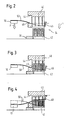
- FIG 2 is an enlarged, schematic view Connector 34 shown.
- This consists of a connector 40, which is attached to the steering wheel 10, and a complementary connector 42, which is attached to a vehicle part 31.
- the on Steering wheel 10 attached connector 40 has two stops 44, 46 on, between which a sliding sleeve 48 is slidably attached is.
- a bistable spring element 50 acts on the sliding sleeve, which is designed here as a leaf spring.
- the leaf spring 50 extends themselves from the sliding sleeve 48 to the steering wheel 10, on which they are its corresponding end is clamped.
- the Leaf spring 50 shown in a first stable position in which it holds the connector 40 in an assembly position and in which it Sliding sleeve 48 is urged against the stop 46.
- leaf spring 50 in the second shown in Figure 4 stable position, it acts on the connector 40 via the sliding sleeve 48 and the stop 44 away from the complementary, connector 42 attached to the vehicle.
- the connector 40 on the steering wheel 10 "floating" attached, so it can be in a plane perpendicular to Plug direction to be moved.
Landscapes
- Physics & Mathematics (AREA)
- Acoustics & Sound (AREA)
- Engineering & Computer Science (AREA)
- Mechanical Engineering (AREA)
- Air Bags (AREA)
- Steering Controls (AREA)
Abstract
Description
- Figur 1 in einer teilgeschnittenen Ansicht ein Lenkrad gemäß dem Stand der Technik;
- Figur 2 in einer schematischen Ansicht einen Teil eines erfindungsgemäßen Lenkrades mit dem Steckverbinder in einer Montagestellung;
- Figur 3 eine Ansicht entsprechend derjenigen von Figur 2 mit dem Lenkrad während der Montage; und
- Figur 4 eine Ansicht entsprechend derjenigen von Figur 2 bei beendeter Montage des Lenkrades.
Claims (5)
- Lenkrad (10) mit einem Steckverbinder (40), der dafür vorgesehen ist, in einen komplementären Steckverbinder (42) eingesteckt zu werden, um ein am Lenkrad angebrachtes Bauteil anzuschließen,
dadurch gekennzeichnet, daß ein bistabiles Federelement (50) vorgesehen ist, das sich ausgehend vom Lenkrad zum Steckverbinder (40) erstreckt, wobei das Federelement (50) eine erste stabile Stellung einnehmen kann, in welcher es den Steckverbinder in eine Montagestellung beaufschlagt, und eine zweite stabile Stellung einnehmen kann, in der es den Steckverbinder (40) von dem komplementären Steckverbinder weg beaufschlagt, und daß der Steckverbinder (40) in Steckrichtung verschiebbar am Lenkrad angebracht ist. - Lenkrad nach Anspruch 1, dadurch gekennzeichnet, daß das Federelement eine Blattfeder (50) ist.
- Lenkrad nach einem der Ansprüche 1 und 2, dadurch gekennzeichnet, daß zwei Federelemente (50) vorgesehen sind.
- Lenkrad nach einem der vorhergehenden Ansprüche, dadurch gekennzeichnet, daß das Federelement (50) an einer Verschiebehülse (48) angreift, die zwischen zwei Anschlägen (44, 46) verschiebbar am Steckverbinder (40) gehalten ist.
- Lenkrad nach einem der vorhergehenden Ansprüche, dadurch gekennzeichnet, daß der Steckverbinder (40) derart am Lenkrad angebracht ist, daß er in einer Ebene senkrecht zur Steckrichtung verschiebar ist.
Applications Claiming Priority (2)
| Application Number | Priority Date | Filing Date | Title |
|---|---|---|---|
| DE20007239U DE20007239U1 (de) | 2000-04-19 | 2000-04-19 | Lenkrad |
| DE2007239U | 2000-04-19 |
Publications (2)
| Publication Number | Publication Date |
|---|---|
| EP1150394A2 true EP1150394A2 (de) | 2001-10-31 |
| EP1150394A3 EP1150394A3 (de) | 2006-12-27 |
Family
ID=7940516
Family Applications (1)
| Application Number | Title | Priority Date | Filing Date |
|---|---|---|---|
| EP01104469A Withdrawn EP1150394A3 (de) | 2000-04-19 | 2001-02-28 | Lenkrad |
Country Status (3)
| Country | Link |
|---|---|
| US (1) | US6322371B2 (de) |
| EP (1) | EP1150394A3 (de) |
| DE (1) | DE20007239U1 (de) |
Families Citing this family (1)
| Publication number | Priority date | Publication date | Assignee | Title |
|---|---|---|---|---|
| DE102018107886B4 (de) | 2018-04-04 | 2021-10-07 | Phoenix Contact Gmbh & Co. Kg | Steckverbindersystem mit einem bistabilen Element |
Family Cites Families (10)
| Publication number | Priority date | Publication date | Assignee | Title |
|---|---|---|---|---|
| US4700794A (en) * | 1986-07-14 | 1987-10-20 | Caterpillar Inc. | Vehicle steering apparatus |
| US6213797B1 (en) * | 1994-07-19 | 2001-04-10 | Methode Electronics, Inc. | Clockspring having non-compliant and compliant roller members |
| DE4436172C2 (de) | 1994-10-10 | 2001-02-01 | Eaton Controls Gmbh | Elektrische Verbindungseinrichtung |
| DE19511410C2 (de) | 1995-03-28 | 2000-06-29 | Framatome Connectors Int | Elektrischer Steckverbinder mit Montagesicherung |
| US5584501A (en) * | 1995-09-15 | 1996-12-17 | Trw Inc. | Vehicle occupant restraint apparatus |
| FR2773915B1 (fr) * | 1998-01-16 | 2000-04-07 | Sc2N Sa | Dispositif de connexion electrique pour vehicule automobile, notamment pour haut de colonne de direction |
| GB2333744B (en) | 1998-01-28 | 2002-01-23 | Delphi Automotive Systems Gmbh | Air bag assembly |
| FR2778379B1 (fr) | 1998-05-05 | 2000-08-04 | Ecia Equip Composants Ind Auto | Systeme de direction notamment pour vehicule automobile |
| DE19855838B4 (de) * | 1998-12-03 | 2006-09-21 | Leopold Kostal Gmbh & Co. Kg | Lenkradmodul umfassend ein Lenkrad und einen Lenkradeinsatz |
| GB2444744B (en) | 2006-12-12 | 2011-05-25 | Advanced Risc Mach Ltd | Apparatus and method for performing re-arrangement operations on data |
-
2000
- 2000-04-19 DE DE20007239U patent/DE20007239U1/de not_active Expired - Lifetime
-
2001
- 2001-02-28 EP EP01104469A patent/EP1150394A3/de not_active Withdrawn
- 2001-04-06 US US09/828,059 patent/US6322371B2/en not_active Expired - Fee Related
Also Published As
| Publication number | Publication date |
|---|---|
| EP1150394A3 (de) | 2006-12-27 |
| DE20007239U1 (de) | 2000-08-24 |
| US6322371B2 (en) | 2001-11-27 |
| US20010034141A1 (en) | 2001-10-25 |
Similar Documents
| Publication | Publication Date | Title |
|---|---|---|
| DE10224757B3 (de) | Steckverbinder mit während des Steckvorgangs verrastender Sekundärverriegelung | |
| DE69411224T2 (de) | Verbindereinrichtung | |
| EP1681746B1 (de) | Elektrischer Steckverbinder | |
| DE102008038563A1 (de) | Verbinder | |
| WO2020239928A1 (de) | Steckverbinder mit verriegelungssystem | |
| DE69921560T2 (de) | Abgeschirmter Verbinder | |
| DE10005297A1 (de) | Kontaktstück für eine elektrische Steckverbindung sowie Verfahren zu dessen Herstellung | |
| WO2016079077A1 (de) | Federkraftklemme | |
| EP0141958B1 (de) | Verriegelbare Steckkupplung | |
| DE4016114C2 (de) | Elektrischer Mehrkontakt-Verbinder, der eine geringe Verbindungs- und Trennkraft erfordert | |
| EP3782235B1 (de) | Direktsteckverbinder | |
| DE29918358U1 (de) | Kuppler für Koaxialsteckverbinder | |
| DE19534205A1 (de) | Elektrischer Steckverbinder | |
| DE10202920A1 (de) | Elektrische Steckverbindung | |
| EP1999822B1 (de) | Elektrisches steckverbindungssystem | |
| DE10025296C2 (de) | Steckverbinder, insbesondere für Airbag-Zündsysteme | |
| DE19640457C2 (de) | Positionierungsmechanismus für einen beweglichen Steckverbinder | |
| EP3766130B1 (de) | Kontaktelement mit einem kontaktkörper und einem daran angeordneten federelement | |
| DE19840648C1 (de) | Elektrischer Steckverbinder | |
| EP1150394A2 (de) | Lenkrad | |
| DE19532623B4 (de) | Elektrischer Stecker mit einem Betätigungsschieber | |
| DE9014856U1 (de) | Isolierkörper für elektrische Kontakte | |
| DE29521491U1 (de) | Elektrischer Steckverbinder | |
| DE19647021A1 (de) | Steckverbinder mit einem Stecker, einem Zwischenteil und einem Gehäuse | |
| DE3928710A1 (de) | Elektrische steckverbindung |
Legal Events
| Date | Code | Title | Description |
|---|---|---|---|
| PUAI | Public reference made under article 153(3) epc to a published international application that has entered the european phase |
Free format text: ORIGINAL CODE: 0009012 |
|
| AK | Designated contracting states |
Kind code of ref document: A2 Designated state(s): AT BE CH CY DE DK ES FI FR GB GR IE IT LI LU MC NL PT SE TR |
|
| AX | Request for extension of the european patent |
Free format text: AL;LT;LV;MK;RO;SI |
|
| PUAL | Search report despatched |
Free format text: ORIGINAL CODE: 0009013 |
|
| AK | Designated contracting states |
Kind code of ref document: A3 Designated state(s): AT BE CH CY DE DK ES FI FR GB GR IE IT LI LU MC NL PT SE TR |
|
| AX | Request for extension of the european patent |
Extension state: AL LT LV MK RO SI |
|
| AKX | Designation fees paid | ||
| STAA | Information on the status of an ep patent application or granted ep patent |
Free format text: STATUS: THE APPLICATION IS DEEMED TO BE WITHDRAWN |
|
| 18D | Application deemed to be withdrawn |
Effective date: 20070901 |
|
| REG | Reference to a national code |
Ref country code: DE Ref legal event code: 8566 |