EP1148933B1 - Methode pour former un module a membrane en fibres creuses tout resine thermoplastique perfluoree - Google Patents
Methode pour former un module a membrane en fibres creuses tout resine thermoplastique perfluoree Download PDFInfo
- Publication number
- EP1148933B1 EP1148933B1 EP00910009A EP00910009A EP1148933B1 EP 1148933 B1 EP1148933 B1 EP 1148933B1 EP 00910009 A EP00910009 A EP 00910009A EP 00910009 A EP00910009 A EP 00910009A EP 1148933 B1 EP1148933 B1 EP 1148933B1
- Authority
- EP
- European Patent Office
- Prior art keywords
- bundle
- hollow fiber
- potting
- fibers
- resin
- Prior art date
- Legal status (The legal status is an assumption and is not a legal conclusion. Google has not performed a legal analysis and makes no representation as to the accuracy of the status listed.)
- Expired - Lifetime
Links
Images


Classifications
-
- B—PERFORMING OPERATIONS; TRANSPORTING
- B01—PHYSICAL OR CHEMICAL PROCESSES OR APPARATUS IN GENERAL
- B01D—SEPARATION
- B01D63/00—Apparatus in general for separation processes using semi-permeable membranes
- B01D63/10—Spiral-wound membrane modules
- B01D63/101—Spiral winding
-
- B—PERFORMING OPERATIONS; TRANSPORTING
- B01—PHYSICAL OR CHEMICAL PROCESSES OR APPARATUS IN GENERAL
- B01D—SEPARATION
- B01D63/00—Apparatus in general for separation processes using semi-permeable membranes
- B01D63/02—Hollow fibre modules
- B01D63/021—Manufacturing thereof
- B01D63/022—Encapsulating hollow fibres
-
- B—PERFORMING OPERATIONS; TRANSPORTING
- B01—PHYSICAL OR CHEMICAL PROCESSES OR APPARATUS IN GENERAL
- B01D—SEPARATION
- B01D63/00—Apparatus in general for separation processes using semi-permeable membranes
- B01D63/02—Hollow fibre modules
- B01D63/021—Manufacturing thereof
-
- B—PERFORMING OPERATIONS; TRANSPORTING
- B01—PHYSICAL OR CHEMICAL PROCESSES OR APPARATUS IN GENERAL
- B01D—SEPARATION
- B01D63/00—Apparatus in general for separation processes using semi-permeable membranes
- B01D63/02—Hollow fibre modules
- B01D63/021—Manufacturing thereof
- B01D63/022—Encapsulating hollow fibres
- B01D63/023—Encapsulating materials
-
- B—PERFORMING OPERATIONS; TRANSPORTING
- B01—PHYSICAL OR CHEMICAL PROCESSES OR APPARATUS IN GENERAL
- B01D—SEPARATION
- B01D63/00—Apparatus in general for separation processes using semi-permeable membranes
- B01D63/02—Hollow fibre modules
- B01D63/021—Manufacturing thereof
- B01D63/0233—Manufacturing thereof forming the bundle
Definitions
- the present invention relates to a method of forming a hollow fiber membrane module. More particularly, it relates to a method of making a hollow fiber module wherein the fibers and potting compound are both formed of one or more thermoplastic, perfluorinated resins.
- a hollow fiber membrane is a tubular filament comprising an inner diameter and an outer diameter having a wall thickness between them. Typically, this wall thickness is porous.
- the inner diameter defines the hollow portion of the fiber and is used to carry fluid, either the feed fluid to be filtered, or the permeating fluid, when the fluid being filtered contacts the outer surface.
- the inner hollow portion is typically referred to as a lumen.
- Hollow fiber membrane devices have been used in many applications in the pharmaceutical, food, beverage and semiconductor industries including gas separation, reverse osmosis, ultrafiltration and particle and bacteria removal with microporous membranes.
- the membrane acts as a permeable barrier, allowing the passage of the carrier fluid and some dissolved or dispensed species, and retaining other selected species do to differences in species size, permeation rates, or other physical or chemical attributes.
- These devices have the unique feature of requiring no support structures for the membranes as a result of their tubular geometry which makes the membrane self supporting.
- fiber is cut or otherwise made to a specific length and a number of fibers are gathered into a bundle.
- a portion of one or both ends of the fiber bundle are encapsulated in a material which fills the interstitial volume between the fibers and forms a tubesheet. This process is sometimes called potting the fibers and the material used to pot the fibers is called the potting material.
- the tubesheet acts as a seal in conjunction with a filtration device, such as a housing or cartridge. If the encapsulation process closes and seals the fiber ends, one or both ends of the fiber bundle are cut across the diameter or otherwise opened. In some cases, the open ends of the fiber bundle are deliberately closed or sealed before potting to prevent the potting material from entering the open ends of the fibers.
- the filtration device supports the tubesheet and provides a volume for the fluid to be filtered and its concentrate, separate from the permeating fluid.
- a fluid stream contacts one surface and separation occurs at the surface or within the depth of the fiber wall. If the fiber outer surface is contacted, the permeating fluid and species pass through the fiber wall and are collected in the lumen where it is directed to the open end or ends of the fiber. If the fiber inner surface is contacted, the fluid stream to be filtered is fed into the open end or ends and the permeating fluid and species pass through the fiber wall and are collected from the outer surface.
- hollow fiber membrane devices are formed by potting the ends of the bundle of fibers in an adhesive such as an epoxy or urethane resins.
- adhesive such as an epoxy or urethane resins.
- These membranes have been found to be deficient in purity as well as in their capability for resisting aggressive or corrosive chemicals and solvents.
- the organic solvent-based solutions used in wafer coating processes in the microelectronics industry will dissolve or swelling and weaken epoxy or urethane potting materials.
- the high temperature stripping baths in this industry consist of highly acidic and oxidative materials which destroy such potting compounds.
- thermoplastic resin in particular to use thermoplastics such as polyethylene or polypropylene and in some instances ultrahigh molecular weight polyethylene. See U.S. 5, 695, 702. While this is more acceptable than the previous epoxy or urethane method, it is limited in the membranes and resins which one may select for use in its method. Unlike epoxy or urethane that have relatively low viscosity and therefore flow easily around and between the fibers to be potted, thermoplastic materials are of higher molecular weight and higher viscosity and are difficult to cause to flow around and between such fibers. Moreover, even when one is able to achieve some flow, the flow is not uniform, leading to irregularities, voids and gaps in the potting. Additionally, these molten thermoplastic materials often have detrimental effects on the fibers themselves, causing fibers to collapse, shrink or melt. This has led to practitioners to adopt various complicated schemes to overcome these problems.
- thermoplastic materials known as perfluorinated thermoplastic polymers. These materials are known by various chemical terms such as poly(TFE-co-PFAVE) resins ("PFAVE"). These materials are also commonly referred to as PFA, MFA or FEP resins. These materials have the chemical inertness similar to that of PTFE resin, but unlike PTFE resin, are thermoplastic and therefore capable of being molded and formed into various shapes easily and economically. Hollow fibers made from such perfluorinated resins have been made. Such fibers and methods for making them are disclosed in U.S. 4, 990,294 and 4,902,456.
- a hollow fiber membrane device formed completely of perfluorinated thermoplastic resins, including the fibers, potting resin and module components such as the end caps and cartridge housing would be highly desirable in that it would provide a completely inert system, especially at elevated temperatures which would be capable of resisting aggressive or corrosive chemicals and organic solvents, which would provide the highest level of purity available as such materials are inherently clean and tend not to have a high level of extractables and which because it is formed of thermoplastic materials could be formed relatively easily and efficiently.
- the present invention provides such a method and a product made by that method.
- a perfluorinated resin in particular a thermoplastic perfluorinated potting resin which has a lower peak melting temperature than the membrane and a reasonably low melt viscosity
- integral potting of the hollow fiber membranes can be achieved.
- the combination of these two characteristics of the potting resin allows for longer contact time between the molten resin and the fibers to attain more complete encapsulation and sealing of the fibers without damage to the fibers or collapse of their lumens.
- An assembled bundle of fibers and potting resin are heated to a temperature above the peak melting point of the potting resin and at or below the peak melting point of the fibers, in order to cause the potting resin to flow and fill any gaps or voids between the fibers which may be present.
- the resultant potted fiber bundle may then be assembled into a cartridge housing made of one or more thermoplastic perfluorinated resins, and sealed with one or more end caps also formed of one or more thermoplastic perfluorinated resins to form an integral all thermoplastic perfluorinated resin based module.
- a cartridge housing made of one or more thermoplastic perfluorinated resins, and sealed with one or more end caps also formed of one or more thermoplastic perfluorinated resins to form an integral all thermoplastic perfluorinated resin based module.
- other inert fluorinated resins may be used as the housing or end caps, such as PTFE resin, in order to create an all fluoropolymer module.
- An embodiment of the present invention provides a method of forming an all thermoplastic, perfluorinated resin hollow fiber module including the steps of contacting a plurality of hollow fiber membranes made of one or more thermoplastic perfluorinated resins with a molten potting resin made of gne or more thermoplastic perfluorinated resins.
- the petting resin having a peak melting point below that of the hollow fibers and which is applied to the hollow fibers at a temperature below the peak melting point of the hollow fibers, cooling the bundle, heating the bundle to a temperature at or above the softening point of the potting resin but below the peak melting point of the hollow fibers for a period of time sufficient to create a fluid-tight seal between the fibers and the potting resin.
- a preferred embodiment of the present invention includes removing a portion of the potting compound in order to open the interior of the fibers to the exterior environment, inserting the bundle into a housing having a first and second end and sealing said bundle into said housing, and applying an end cap to the first and second ends of the housing in order to form an integral, all perfluorinated thermoplastic hollow fiber module.
- thermoplastic hollow fiber module in accordance with the present convention can be accomplished through the use of one or more thermoplastic perfluorinated resins, both as the hollow fiber membrane and potting compound as well as the components of the module itself.
- One aspect of the present invention is to eliminate voids and gaps In the potting material via the use of a post-potting heating treatment. This treatment allows for the potting resin to be melted such that it flows between the fibers and eliminates any gaps or voids that may exist and to allow for adequate bonding of the fibers to the potting materials.
- the method of fabricating a hollow fiber membrane device begins with the formation of the thermoplastic perfluorinated resin based hollow fiber membranes such as are taught in U.S. 4, 990, 294 and U.S. 4, 902, 456, and co-pending application US Patent Application 60/117,852 and 60/117,854, filed January 29,1999, the teachings of which are incorporated herein in their entireties.
- the fibers are then arranged and then formed into a bundle by applying one or more streams of molten potting compound, which consists of a perfluorinated thermoplastic resin or blend of such resins, to one or more ends of the individual fibers, while such fibers after having the stream or streams applied are wound upon themselves or a mandrel to form the bundle.
- molten potting compound which consists of a perfluorinated thermoplastic resin or blend of such resins
- the potting compound, the fibers and to extent it may be used, the mandrel may be made of one or more thermoplastic perfluorinated resins such as poly(TFE-co-PFAVE) resins.
- These resins include poly(tetrafluoroethylene-co-perfluoro (alkylvinylether)) resins, often called by the term PFA or MFA or poly(tetrafluoroethylene-co-hexafluoropropylene) resin, often called FEP or blends thereof.
- the alkyl group is preferably either a methyl or propyl group or blends thereof.
- Such resins are commercially available.
- TEFLON® PFA resin available from E.I. duPont de Nemours of Wilmington, Delaware or HYFLON® MFA resin available from Ausimont USA of Thorofare, New Jersey or NEOFLON® PFA available from Daikin Industries of Japan.
- the perfluorinated thermoplastic resin selected for the fibers should have a peak melting point that is greater than the peak melting point of the perfluorinated thermoplastic resin selected for the potting compound. This allows for adequate bonding of the fibers to the potting material without detrimental effects to the fiber caused by the temperature of the potting material.
- Fibers may be made from a poly(tetrafluoroethylene-co-perfluoro(alkylvinylether) wherein the alkyl group is mainly methyl, such as HYFLON®620 resin available from Ausimont USA of Thorofare, New Jersey which has a peak melting point of about 285°C or from a poly(tetrafluoroethylene-co-hexafluoropropylene) resin, such as TEFLON®FEP 100 resin available from E.I. duPont de Nemours of Wilmington, Delaware which has a peak melting point of about 270°C.
- HYFLON®620 resin available from Ausimont USA of Thorofare, New Jersey which has a peak melting point of about 285°C
- TEFLON®FEP 100 resin available from E.I. duPont de Nemours of Wilmington, Delaware which has a peak melting point of about 270°C.
- the potting compound has a peak melting point at least 5 °C below that of the fibers.
- the peak melting point of the potting compound is at least about 10°C below that of the fibers. More preferably, it has a peak melting point of at least about 25°C below that of the fibers.
- the potting compound will be a perfluorinated thermoplastic resin or blend of such resins having a peak melting point of less than about 275°C, preferably having a peak melting point of from about 230°C to about 275°C. More preferably, the potting resin has a peak melting point of less than about 260°C.
- the potting compound should have a relatively low melt viscosity.
- the melt flow index(MFI) MFI as defined by A. S. T. M. D2116, at 372°C and 5kg.load
- the melt flow index (MFI as defined by A. S. T. M. D2116, at 372°C and 5kg.load) of the perfluorinated thermoplastic resin or resins used in the potting compound should be greater than 100g/10 min.
- the melt flow index is greater than 150 g/10 min. More preferably, the melt flow index is greater than 200g/10 min. It has been found that the higher the melt flow index, the better the resultant product.
- a resin or resins may be used which have a lower melt flow index than the values described above, however one will find that the process becomes more difficult and the seal between the fibers and the potting compound may become incomplete.
- poly(tetrafluoroethylene-co-perfluoro(alkylvinylether) useful as a potting material is sold as HYFLON®940 AX resin from Ausimont USA Inc of Thorofare,New Jersey. It has a peak melting point of from about 250°C to 260°C and a melt flow index of about 130g/10 mins..
- An example of a suitable low viscosity poly(tetrafluoroethylene-co-hexafluoropropylene) resin useful as a potting compound is taught in U.S. Patent 5, 266, 639, especially those at the lower end of melt temperatures.
- a flat substantially parallel array of these fibers is prepared.
- the array is formed according to the teachings of U.S. 5, 695, 702, the teachings of which are incorporated by reference herein.
- the fibers are first formed into an array by arranging individual fibers substantially parallel to each other.
- the fibers may be spaced apart from each other or if desired, they may be touching each other. Which arrangement is selected depends upon the packing density desired in the final module.
- a packing density typically, one wishes to have a packing density of between 40 and 70%, more preferably between 45 and 65%.
- Packing density is defined as the ratio, expressed as a percentage, of the total cross-sectional area of all the fibers in a bundle to the cross-sectional area of the final potted fiber bundle. If the packing density is too low, then filtration efficiency is compromised. If the density is too high, then there is the danger that incomplete potting will occur or that filtration efficiency will be compromised as the fluid will have difficulty reaching the inner fibers of the bundle.
- any means used to make the array should be confined to areas that will normally be trimmed from the finished hollow fiber module.
- the array may be fabricated by either winding the length of the array upon itself or upon a mandrel.
- the mandrel if chosen, is preferably circular in cross section, however other cross sections, such as oval, square, rectangular or polygonal may also be used.
- the circumference of the mandrel is chosen to be an integer multiple of the desired length of the hollow fiber member elements which form the finished array.
- it is preferably driven by a mechanical device such as a controller capable of controlling both rotational speed and tension applied to the array.
- the wound hollow fiber membrane array is arranged such that it is fed as a single layer of fibers, with the windings being substantially parallel to each other either in contiguous contact with or spaced uniformity apart from one another.
- the array is fabricated by winding a continuous length of hollow fiber membrane 11 on a rotating mandrel 12 having a circular cross section as shown in Figure 1.
- the circumference of the mandrel is chosen to be an integer multiple of the desired length of the hollow fiber membrane elements which are to comprise the finished array.
- the mandrel is driven by a controller 13 capable of controlling both the rotational speed of the mandrel and the tension applied to the hollow fiber membrane.
- the controller includes a fiber feed mechanism 14 which moves a pulley 15 parallel to the central axis of the mandrel and guides the hollow fiber membrane as it is being wound to control the spacing between adjacent fiber segments.
- the wound hollow fiber membrane is arranged in a single layer, with the windings being substantially parallel to one another either in contiguous contact with, or spaced uniformly apart from, one another.
- the controller 13 stops the winding operation and one or more strips of an adhesive tape 22 (Figure 2) are applied to the outer surface of the hollow fiber membrane segments positioned along the length of the mandrel in an orientation parallel to its axis of rotation and perpendicular to the central axes of the individual hollow fiber segments. More than one strip of tape can be used, the circumferential spacing between strips being equal to the desired axial length of the membrane fibers in the array 21.
- the tape extends from the first hollow fiber membrane segment wound on the mandrel to the least and preferably extends about 1 cm. beyond each end of the fiber array.
- a cutting guide may be used to slit the hollow fiber membrane segments along the middle of the entire length of the tape 22 such that the hollow fiber membranes 11 remain joined together by the now halved strip of tape.
- one or more hollow fiber membrane arrays 21 are produced, with the fiber elements being secured to one another at their ends by the tape thereby making it easily removed from the mandrel 12.
- the edges 23 of the rectangular hollow fiber membrane array 21 are defined as the two surfaces formed by the end portions of the individual hollow fiber membrane elements comprising the array; the ends 24 of the array are defined by the outermost surfaces of the first and last hollow fiber membrane elements in the array.
- Figure 2 shows in the plan view an array formed in accordance with the above procedures.
- the arrays may be spliced together end-to-end by means of an adhesive or other bonding mechanism to form a larger array. Any number of arrays may be so spliced together in the manner described above to form a larger array having tape extensions at the edges of both ends of the array.
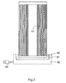
- the next operation in the fabrication of a hollow fiber membrane module is the winding of the fiber array into a bundle and the corresponding formation of a pair of tubesheets 43 at one or more of the edges 23 of the array 21.
- This process is shown schematically in Figures. 3 and 4.
- An extruder, preferably a single screw extruder, 31 is used to feed a thermoplastic sealing polymer to a dual slot extrusion die 32 which produces two polymer extrusions 35 in the form of a stream.
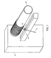
- a suitable length of thermoplastic tube 41 is mounted on a removable winding mandrel 42 positioned below the extrusion die, with the rotational axis of the mandrel being parallel to a line connecting the two outlets of the extrusion die.
- Stepper motors (not shown) are used to adjust the speed of rotation and distance between the mandrel and the die.
- a set of gas heaters 33 mounted on a retractable slide (not shown) is used to preheat the tube 41 prior to the fabrication of the tubesheets.
- the functions of the various elements described above are regulated by a programmable, microprocessor-based controller 34.
- the tube 41 Before the winding of the array 21 and the formation of the tubesheets 43, the tube 41 must be pre-heated using the heaters 33. This step is necessary to obtain a good bond between the tubesheet and the tube. Rotation of the winding mandrel 42 and the tube is begun and the gas heaters are activated such that a hot gas stream impinges on the portions of the tube where the tubesheets will be formed. After a suitable time, the heaters are removed and the polymer extrusions 35 are applied to the tube.
- the leading edge of the hollow fiber membrane array 21 is positioned under and parallel to the tube with the adhesive side of the extended strip of tape 22 facing the tube.
- the tape is then brought into contact with the tube outboard of the tubesheets 43 and allowed to wind up on the tube as the rotational speed and position of the winding mandrel 42 and tube are adjusted by the process controller 34.
- a slight tension is maintained on the hollow fiber array to keep the fibers in contact with the polymer extrusions.
- the tape extensions are fastened to the previous fiber layer to form a fiber bundle 44.
- the tubesheets may be built up to a larger diameter depending on the requirements of the rest of the module assembly process. In this case, the rotation of the winding mandrel continues as the tubesheets are allowed to cool.
- a post-formation heating step is performed.
- the potted ends are heated to a temperature below the peak melting point of the hollow fiber membranes.
- the temperature selected is above the peak melting point of the potting resin, but below the peak melting point of the hollow fiber membranes.
- the heating temperature may range from 250°C to 300°C.
- An alternative means for describing this temperature is that it should be at least 10°C below the peak melting point of the fibers, preferably at least 15°C and more preferably, at least 25°C below the peak melting point of the fibers.
- This step causes the potting material to melt, and flow between the fibers in order to eliminate any voids or gaps which may exist.
- One advantage to using the post-formation heating step is that the criticality of the initial extrusion step is not as important as the post-formation heating step allows for the elimination of any voids formed during the extrusion step. This is of particular interest and importance in that the extrusion step often is very slow and laborious.
- the time required for the post-formation heating step will vary widely depending upon such factors as the peak melting point of the potting compound and the fibers, the viscosity/melt flow index of the potting compound, the perceived level of voids or gaps which must be eliminated, etc.. Typically, the process requires from about 1 hour to about 24 hours. It has been found that the longer one is able to perform the heating step, without damage to the fibers, the better the result. Preferably, the heating step occurs from about 3 to about 12 hours, more preferably from about 5 to about 8 hours.
- the heating step occurs with the tubesheet in a vertical orientation with one end being treated at a time. Further, the end or ends may be treated in a horizontal orientation provided that little or no slumping occurs. This is particularly possible with higher viscosity or lower melt flow index potting compounds.
- the heat treatment occurs prior to the formation of the filtration cartridge. Alternatively, the heat treatment may occur after the tubesheet has been inserted into the housing or end caps. In this embodiment, the heat treatment acts both as a mechanism for removing any gaps or voids and as the sealing mechanism for attaching the bundle to the housing or end caps. Additionally, while it is preferred that the heating step occur before the lumens of the fibers are opened, one can perform the step after the lumens have been opened provided that some means is used to maintain the opened ends of the lumens.
- Figure 5 shows a preferred embodiment of the post-formation heat treatment.
- one end 43A of the tubesheet 43 is placed into a cup-like holder 50 which has a depth and diameter about the same as the potted end 43A.
- the holder 50 is mounted into a recess 51 formed in a metal heating block 52.
- the block 52 is heated with one or more electrical heating bands 53.
- the holder 50 is preferably made of a thermally conductive material, such as metal or ceramics may also be used.
- an oven including but limited to radiant, convection or microwave ovens in lieu of the holder/block arrangement above.
- the use of a holder or holders in an oven or other heating means may be desirable.
- the holders contain the area into which the potting material may flow. This concentrates the flow to the areas between the fibers.
- two holders at the same time in order to treat both ends of the tubesheet simultaneously whether the heating is via a heating block arrangement, an oven or other well known means in the art.
- Either one or both of the end portions of the sealed fiber bundle can be trimmed to expose the fiber lumens and further machining may be performed to provide a means for sealing the fiber bundle into a suitable housing or the fiber bundle may be contoured to provide details suitable for thermoplastically bonding it to the components of a pressure housing of the same or similar resin material in order to produce a hollow fiber module.
- Figure 6 shows the details of the fiber bundle 44 and corresponding tubesheets 43 (labeled in this figure as 43b and 43t to represent the bottom and top orientations shown in the drawing) after the postheating step which have been assembled into a hollow fiber module.
- this module is formed of the same resin as either the hollow fibers or the potting material in order to create an all perfluorinated resin device.
- this can be accomplished by employing conventional methods of fusion bonding of plastic components.
- the housing may be made of a similar and compatible resin such as PTFE.
- PTFE a similar and compatible resin
- other means of sealing the tubesheet to be housing such as O-rings or mechanical seals, must be used.
- the bottom tubesheet 43b is bonded to an inside cap 71.
- the filtrate collected at that tubesheet is directed to a top end cap 72 through the tube 41.
- the housing shell and the top tubesheet 43t of the bundle are simultaneously bonded to the top end-cap.
- an outside end-cap 73 is bonded to the bottom of a housing shell 74.
- Suitable connectors are also added to provide means of connecting the module to a feed and to an effluent line.
- Fiber array bundle arrangements may also vary in that single-ended tubesheets for short length membrane modules may be fabricated as well as multiple tubesheets.
- the hollow fiber elements must be sealed at the opposite end of the tubesheet.
- intermediate tubesheets used primarily as support members, may or may not form integral seals around the hollow fiber membranes for particularly long modules.
- multiple bundles may be produced simultaneously using integrally sealed, multiple tubesheets which are subsequently cut to form individual fiber bundles.
- planar laminated arrays are also contemplated to be within the purview of this invention, in which case rectangular fiber arrays may be mounted on top of one another. The use of woven arrays is also possible.
- An alternative method of making a product according to this invention is to form a mat or flat array of fibers using the thermoplastic, perfluorinated resin as the tape binder for the array and then rolling the array into a cylindrical or other desired shape and subjecting the ends to the post-formation heating step to form an integral, sealed tubesheet.
- a mat of fibers in the form of an array would have a stream of potting material extruded along two of its portions of its length, preferably in parallel and spaced apart from each other at a desired distance equal to that of the finished tubesheet. Further, one can adhere or secure individual fibers to two parallel strips of thermoplastic, perfluorinated resin.
- O-rings preferably formed of a perfluorinated resin such as thermoplastic perfluorinated resin or PTFE resin,
- Microporous thermoplastic perfluorinated hollow fiber membranes made from Ausimont's MFA 620 resin according to the teachings of US Patents 4, 990, 294 and 4, 902, 456 were used for potting in this example.
- the peak melting temperature of the fibers as measured by differential scanning calorimetry (DSC) was 289°C.
- the outside diameter of each fiber was 1000 microns and the inside diameter was 600 microns. Porosity was approximately 65%.
- the potting resin used was a thermoplastic perfluorinated resin available from Ausimont as MFA19405/13 resin.
- the peak melting temperature of this resin was 258°C and its melt flow rate (MFI at 5kg, 372°C as described by ASTM D 2116) was 124g/10 minutes.
- the potted sample was tested for potting integrity by placing and sealing both ends via O-rings inside a clear plastic housing. Iso-propyl-alcohol (IPA) was used to wet the fibers and fill the inside of the housing, making sure that all of the potted areas were covered with IPA. Both ends of the housing were capped with one of the caps having an inlet for pressurized air. Air pressure was slowly introduced and increased via the inlet on the one end. Simultaneously, the inside of the holder was examined visually for air bubbles originated from the potting area. No bubbles were observed at either end up to at least 15 psi, indicating integral potting had been achieved.
- IPA Iso-propyl-alcohol
Landscapes
- Chemical & Material Sciences (AREA)
- Chemical Kinetics & Catalysis (AREA)
- Engineering & Computer Science (AREA)
- Manufacturing & Machinery (AREA)
- Separation Using Semi-Permeable Membranes (AREA)
Claims (12)
- Procédé de fabrication d'un module de membranes faites de fibres creuses entièrement en résines perfluorées thermoplastiques, comprenant les étapes suivantes :- mettre plusieurs membranes faites de fibres creuses se composant d'une ou de plusieurs résines thermoplastiques perfluorées en contact avec une ou plusieurs résines d'empotage thermoplastiques perfluorées fondues de manière à former un réseau parallèle desdites membranes ;- chauffer lesdites une ou plusieurs résines d'empotage à une température suffisamment au-dessus de leur point de fusion maximal mais au niveau ou en dessous du point de fusion maximal des membranes de sorte qu'elles s'appliquent aux dites membranes à une température de contact qui fait que lesdites une ou plusieurs résines d'empotage s'écoulent autour desdites membranes faites de fibres creuses de manière à former un faisceau de membranes faites de fibres creuses;- faire refroidir ledit faisceau ; et- chauffer ledit faisceau à une température inférieure au point de fusion maximal des fibres creuses et supérieure ou égale au point de fusion maximal desdites une ou plusieurs résines d'empotage, ceci pendant une période suffisante pour former un joint étanche aux fluides entre lesdites une ou plusieurs résines d'empotage et les membranes faites de fibres creuses.
- Procédé selon la revendication 1, dans lequel le point de fusion maximal de la résine ou des résines d'empotage est d'au moins 5° C inférieur à celui des membranes faites de fibres creuses, par exemple d'au moins 10° C inférieur au point de fusion maximal des membranes faites de fibres creuses.
- Procédé selon la revendication 1, dans lequel lesdites une ou plusieurs résines des membranes faites de fibres creuses et résines d'empotage thermoplastiques perfluorées sont choisies dans le groupe comprenant des homopolymères, des copolymères, des mélanges d'un ou de plusieurs homopolymères, des mélanges d'un ou de plusieurs copolymères, et des mélanges d'un ou de plusieurs homopolymères et copolymères des résines perfluorées, comme le groupe comprenant des résines de poly(TFEco-PFAVE) et des mélanges de ces dernières.
- Procédé selon la revendication 1, dans lequel le faisceau est chauffé à une température supérieure au point de fusion maximal de la résine ou des résines d'empotage.
- Procédé selon la revendication 1, dans lequel lesdites plusieurs membranes faites de fibres creuses sont formées avant de mettre lesdites membranes en contact avec lesdites résines d'empotage en formant lesdites membranes en même temps selon une relation contiguë, ou en formant lesdites membranes en même temps selon une relation espacée.
- Procédé selon la revendication 1, dans lequel la résine d'empotage consiste en un flux fin déposé dans une zone définie à proximité d'une extrémité dudit réseau de membranes, le procédé comprenant éventuellement une étape consistant à mettre en contact un second flux fin de résine d'empotage à proximité de l'extrémité opposée dudit réseau de membranes.
- Procédé selon la revendication 1, comprenant en outre des étapes consistant à former un réseau parallèle desdites membranes puis à enrouler en spirale ledit réseau autour d'un axe qui est parallèle à l'axe longitudinal dudit réseau de membrane tout en appliquant simultanément ladite résine d'empotage au réseau de membranes de manière à former un faisceau circulaire de fibres ayant au moins une extrémité empotée, et comprenant éventuellement une étape consistant à poursuivre l'application de ladite résine d'empotage après que ledit faisceau circulaire soit formé de manière à créer une feuille tubulaire d'un diamètre prédéterminé autour d'au moins une extrémité desdites membranes faites de fibres creuses.
- Procédé selon la revendication 1, comprenant en outre une étape consistant à couper ladite au moins une extrémité empotée du faisceau de manière orthogonale par rapport à l'axe longitudinal desdites membranes faites de fibres creuses de manière à former ledit faisceau avec au moins une surface d'extrémité plane comportant des lumières exposées, et comportant éventuellement l'étape consistant à monter ledit faisceau dans un boîtier de cartouche, par exemple par collage par fusion.
- Procédé selon la revendication 1, comprenant en outre les étapes consistant à :a) mettre en forme plusieurs membranes faites de fibres creuses formées d'une ou de plusieurs résines thermoplastiques perfluorées, selon un agencement parallèle dans lequel les fibres sont disposées selon un agencement parallèle le long de la longueur des fibres ; ensuiteb) enrouler lesdites plusieurs fibres creuses autour d'un axe qui est parallèle à la longueur des membranes faites de fibres creuses de manière à former un faisceau possédant deux extrémités de faisceau ;c) en même temps que l'étape b), extruder un écoulement fondu d'une résine thermoplastique perfluorée ayant un point de fusion maximal inférieur d'au moins 5° C au point de fusion maximal des membranes faites de fibres creuses et ayant un indice d'écoulement à l'état fondu de 100 g/10 min. ou plus, puis diriger ladite résine sur au moins une des deux extrémités de faisceau afin d'empoter au moins une extrémité dans ladite résine;d) faire refroidir le faisceau ;e) faire chauffer le faisceau au niveau de chaque extrémité empotée à une température supérieure ou égale au point de fusion maximal de la résine de l'écoulement mais inférieure au point de fusion maximal des fibres creuses ; etf) exposer les extrémités des lumières des membranes faites de fibres creuses au niveau de chaque extrémité empotée de manière à communiquer avec l'extérieur du faisceau.
- Procédé selon la revendication 9, dans lequel les deux extrémités du faisceau sont empotées par l'écoulement fondu de résine thermoplastique perfluorée, et éventuellement les deux extrémités du faisceau sont exposées de sorte que les extrémités des lumières des membranes faites de fibres creuses puissent communiquer avec l'extérieur du faisceau.
- Procédé selon la revendication 9, comprenant en outre les étapes consistant à :g) insérer le faisceau dans un boîtier pour le faisceau possédant une première extrémité et une seconde extrémité et un intérieur de boîtier cylindrique de forme appropriée pour contenir le faisceau de membranes, un premier moyen pour sceller la première extrémité du faisceau à l'intérieur du boîtier à proximité de sa première extrémité, un second moyen pour sceller la seconde extrémité du faisceau à l'intérieur du boîtier à proximité de sa seconde extrémité, le boîtier comprenant un ou plusieurs moyens permettant de diviser le faisceau en au moins deux régions comprenant un espace côté enveloppe extérieur à la partie du faisceau située entre les extrémités empotées, et un espace comportant les lumières ; ensuiteh) appliquer un premier capuchon d'extrémité à proximité la première extrémité du boîtier afin de sceller la première extrémité du boîtier ; ensuitei) appliquer un second capuchon d'extrémité à proximité la seconde extrémité du boîtier afin de sceller la seconde extrémité du boîtier ; etj) fournir un accès côté enveloppe dans le boîtier et au moins un accès dans l'un au moins des premier et second capuchons d'extrémité.
- Procédé selon la revendication 9, dans lequel le composé d'empotage possède un indice d'écoulement à l'état fondu se situant dans une plage de 100 à 200 g/10 mins.
Applications Claiming Priority (3)
| Application Number | Priority Date | Filing Date | Title |
|---|---|---|---|
| US11785699P | 1999-01-29 | 1999-01-29 | |
| PCT/US2000/002193 WO2000044483A2 (fr) | 1999-01-29 | 2000-01-27 | Procede permettant de former un module des fibres creuses thermoplastiques, perfluorinees |
| US117856P | 2008-11-25 |
Publications (2)
| Publication Number | Publication Date |
|---|---|
| EP1148933A2 EP1148933A2 (fr) | 2001-10-31 |
| EP1148933B1 true EP1148933B1 (fr) | 2007-01-24 |
Family
ID=22375203
Family Applications (1)
| Application Number | Title | Priority Date | Filing Date |
|---|---|---|---|
| EP00910009A Expired - Lifetime EP1148933B1 (fr) | 1999-01-29 | 2000-01-27 | Methode pour former un module a membrane en fibres creuses tout resine thermoplastique perfluoree |
Country Status (6)
| Country | Link |
|---|---|
| EP (1) | EP1148933B1 (fr) |
| AU (1) | AU3217400A (fr) |
| DE (1) | DE60033135T2 (fr) |
| ES (1) | ES2280199T3 (fr) |
| TW (1) | TWI292335B (fr) |
| WO (1) | WO2000044483A2 (fr) |
Cited By (2)
| Publication number | Priority date | Publication date | Assignee | Title |
|---|---|---|---|---|
| DE102016004573A1 (de) | 2015-04-22 | 2016-10-27 | Mann+Hummel Gmbh | Hohlfasermodul, Fluidbehandlungseinrichtung und Verfahren zur Ausbildung eines Hohlfasermoduls |
| EP3201979A1 (fr) * | 2014-10-01 | 2017-08-09 | Mahle International GmbH | Procédé de fabrication d'un bloc humidificateur destiné à un humidificateur |
Families Citing this family (14)
| Publication number | Priority date | Publication date | Assignee | Title |
|---|---|---|---|---|
| US6802972B1 (en) | 1999-01-29 | 2004-10-12 | Mykrolis Corporation | Microporous hollow fiber membranes from perfluorinated thermoplastic polymers |
| US6582496B1 (en) | 2000-01-28 | 2003-06-24 | Mykrolis Corporation | Hollow fiber membrane contactor |
| JP4514959B2 (ja) | 1999-01-29 | 2010-07-28 | マイクロリス・コーポレイション | 中空繊維膜の製造方法 |
| US6921482B1 (en) | 1999-01-29 | 2005-07-26 | Mykrolis Corporation | Skinned hollow fiber membrane and method of manufacture |
| US7347937B1 (en) | 2000-01-28 | 2008-03-25 | Entegris, Inc. | Perfluorinated thermoplastic filter cartridge |
| DE102004004212B4 (de) * | 2004-01-27 | 2007-02-08 | Koch Membrane Systems Gmbh | Membranfiltereinheit und Verfahren zur Herstellung der Membranfiltereinheit |
| GB0913645D0 (en) | 2009-08-05 | 2009-09-16 | Nano Porous Solutions Ltd | A method of forming a fluid separation filter for use in a fluid separation device |
| DE102010027973A1 (de) * | 2010-04-20 | 2011-10-20 | Ilias-Medical Gmbh | Verfahren und Vorrichtung zur Herstellung eines Membranmodus |
| US8540081B2 (en) | 2011-03-16 | 2013-09-24 | Markel Corporation | Fluoropolymer hollow fiber membrane with fluoro-copolymer and fluoro-terpolymer bonded end portion(s) and method to fabricate |
| EP3319713A1 (fr) * | 2015-07-09 | 2018-05-16 | Entegris, Inc. | Résines d'enrobage mixtes et leur utilisation |
| DE102016211903A1 (de) | 2016-06-30 | 2018-01-04 | membion Gmbh | Verfahren zur Herstellung eines Membranfilters |
| DE102016009914B4 (de) * | 2016-08-18 | 2019-08-08 | Berghof Membrane Technology GmbH | Hohlmembranmatte, Hohlmembranmodul und Verfahren zu dessen Herstellung |
| CN111867707A (zh) * | 2018-03-15 | 2020-10-30 | 恩特格里斯公司 | 氟化过滤薄膜、过滤器及方法 |
| CN111437727B (zh) * | 2020-04-22 | 2022-04-19 | 北京工业大学 | 一种制作中空纤维膜组件均匀分布膜丝的方法及装置 |
Family Cites Families (6)
| Publication number | Priority date | Publication date | Assignee | Title |
|---|---|---|---|---|
| DE3577404D1 (de) * | 1984-09-10 | 1990-06-07 | Hr Textron Inc | Vollstaendig aus fluorkohlenstoffharz hergestelltes filterelement. |
| US4980060A (en) * | 1987-07-13 | 1990-12-25 | Asahi Kasei Kogyo Kabushiki Kaisha | Hollow fiber membranes with fusion-bonded end portions |
| JP3077260B2 (ja) * | 1991-06-01 | 2000-08-14 | 住友電気工業株式会社 | 中空糸状多孔質分離膜エレメントおよびその製造方法 |
| US5695702A (en) * | 1994-07-01 | 1997-12-09 | Millipore Corporation | Thermoplastic hollow fiber membrane module and method of manufacture |
| JP3431166B2 (ja) * | 1995-09-21 | 2003-07-28 | 旭化成株式会社 | 中空系膜モジュール |
| JP3077020B2 (ja) * | 1996-04-25 | 2000-08-14 | 株式会社キッツ | 中空糸型分離膜モジュール |
-
2000
- 2000-01-27 EP EP00910009A patent/EP1148933B1/fr not_active Expired - Lifetime
- 2000-01-27 ES ES00910009T patent/ES2280199T3/es not_active Expired - Lifetime
- 2000-01-27 AU AU32174/00A patent/AU3217400A/en not_active Abandoned
- 2000-01-27 WO PCT/US2000/002193 patent/WO2000044483A2/fr active IP Right Grant
- 2000-01-27 DE DE60033135T patent/DE60033135T2/de not_active Expired - Lifetime
- 2000-01-28 TW TW089101501A patent/TWI292335B/zh not_active IP Right Cessation
Cited By (2)
| Publication number | Priority date | Publication date | Assignee | Title |
|---|---|---|---|---|
| EP3201979A1 (fr) * | 2014-10-01 | 2017-08-09 | Mahle International GmbH | Procédé de fabrication d'un bloc humidificateur destiné à un humidificateur |
| DE102016004573A1 (de) | 2015-04-22 | 2016-10-27 | Mann+Hummel Gmbh | Hohlfasermodul, Fluidbehandlungseinrichtung und Verfahren zur Ausbildung eines Hohlfasermoduls |
Also Published As
| Publication number | Publication date |
|---|---|
| WO2000044483A2 (fr) | 2000-08-03 |
| ES2280199T3 (es) | 2007-09-16 |
| AU3217400A (en) | 2000-08-18 |
| WO2000044483A3 (fr) | 2000-11-23 |
| DE60033135D1 (de) | 2007-03-15 |
| DE60033135T2 (de) | 2007-10-11 |
| TWI292335B (en) | 2008-01-11 |
| EP1148933A2 (fr) | 2001-10-31 |
Similar Documents
| Publication | Publication Date | Title |
|---|---|---|
| EP1148933B1 (fr) | Methode pour former un module a membrane en fibres creuses tout resine thermoplastique perfluoree | |
| EP0768913B1 (fr) | Module de membrane a fibres creuses et procede de fabrication | |
| US6077376A (en) | Process for producing a tubular membrane assembly | |
| EP2686090B1 (fr) | PROCÉDÉ DE FABRICATION D' UNE MEMBRANE À FIBRES CREUSES EN PTFE AVEC UN ENROBAGE en POLYMÈRE FLUORÉ | |
| EP0604972B1 (fr) | Cartouches de tissu avec membrane à fibres creuses et modules ayant des plaques tubulaires en matière thermoplastique résistant aux solvents et méthodes de fabrication | |
| US5584997A (en) | Separation module and bundle unit of hollow thread-type porous membrane elements and methods of producing same | |
| KR101257959B1 (ko) | 포팅된 중공 도관을 구비한 교환 장치 | |
| EP1148932B1 (fr) | Procede de fabrication de membranes a fibres creuses | |
| KR100607021B1 (ko) | 퍼플루오르화 열가소성 수지제 필터 카트리지 | |
| EP2464502A1 (fr) | Préparation de module à membrane plane | |
| JP2021102768A (ja) | ブレンドしたポッティング樹脂及びその使用 | |
| US7347937B1 (en) | Perfluorinated thermoplastic filter cartridge | |
| JP3385668B2 (ja) | 中空糸モジュールの製造方法及び製造用治具 | |
| JP5644393B2 (ja) | 中空糸膜シートの製造方法、中空糸膜モジュールの製造方法 | |
| AU730631B2 (en) | A process for producing a tubular membrane assembly |
Legal Events
| Date | Code | Title | Description |
|---|---|---|---|
| PUAI | Public reference made under article 153(3) epc to a published international application that has entered the european phase |
Free format text: ORIGINAL CODE: 0009012 |
|
| 17P | Request for examination filed |
Effective date: 20010731 |
|
| AK | Designated contracting states |
Kind code of ref document: A2 Designated state(s): AT BE CH CY DE DK ES FI FR GB GR IE IT LI LU MC NL PT SE |
|
| RAP1 | Party data changed (applicant data changed or rights of an application transferred) |
Owner name: MILLIPORE CORPORATION |
|
| RBV | Designated contracting states (corrected) |
Designated state(s): DE ES FR GB IT NL |
|
| 17Q | First examination report despatched |
Effective date: 20050426 |
|
| RAP1 | Party data changed (applicant data changed or rights of an application transferred) |
Owner name: MYKROLIS CORPORATION |
|
| RAP1 | Party data changed (applicant data changed or rights of an application transferred) |
Owner name: ENTEGRIS, INC. |
|
| GRAP | Despatch of communication of intention to grant a patent |
Free format text: ORIGINAL CODE: EPIDOSNIGR1 |
|
| RTI1 | Title (correction) |
Free format text: METHOD OF FORMING AN ALL THERMOPLASTIC, PERFLUORINATED RESIN HOLLOW FIBER MEMBRANE MODULE |
|
| GRAS | Grant fee paid |
Free format text: ORIGINAL CODE: EPIDOSNIGR3 |
|
| GRAA | (expected) grant |
Free format text: ORIGINAL CODE: 0009210 |
|
| AK | Designated contracting states |
Kind code of ref document: B1 Designated state(s): DE ES FR GB IT NL |
|
| REG | Reference to a national code |
Ref country code: GB Ref legal event code: FG4D |
|
| REF | Corresponds to: |
Ref document number: 60033135 Country of ref document: DE Date of ref document: 20070315 Kind code of ref document: P |
|
| ET | Fr: translation filed | ||
| REG | Reference to a national code |
Ref country code: ES Ref legal event code: FG2A Ref document number: 2280199 Country of ref document: ES Kind code of ref document: T3 |
|
| PLBE | No opposition filed within time limit |
Free format text: ORIGINAL CODE: 0009261 |
|
| STAA | Information on the status of an ep patent application or granted ep patent |
Free format text: STATUS: NO OPPOSITION FILED WITHIN TIME LIMIT |
|
| 26N | No opposition filed |
Effective date: 20071025 |
|
| REG | Reference to a national code |
Ref country code: FR Ref legal event code: CA |
|
| PGFP | Annual fee paid to national office [announced via postgrant information from national office to epo] |
Ref country code: NL Payment date: 20110128 Year of fee payment: 12 Ref country code: IT Payment date: 20110125 Year of fee payment: 12 Ref country code: FR Payment date: 20110301 Year of fee payment: 12 Ref country code: DE Payment date: 20110127 Year of fee payment: 12 |
|
| PGFP | Annual fee paid to national office [announced via postgrant information from national office to epo] |
Ref country code: GB Payment date: 20110125 Year of fee payment: 12 Ref country code: ES Payment date: 20110126 Year of fee payment: 12 |
|
| REG | Reference to a national code |
Ref country code: DE Ref legal event code: R082 Ref document number: 60033135 Country of ref document: DE Representative=s name: MAI DOERR BESIER EUROPEAN PATENT ATTORNEYS - E, DE Ref country code: DE Ref legal event code: R082 Ref document number: 60033135 Country of ref document: DE Representative=s name: MAI DOERR BESIER PATENTANWAELTE, DE |
|
| REG | Reference to a national code |
Ref country code: NL Ref legal event code: V1 Effective date: 20120801 |
|
| GBPC | Gb: european patent ceased through non-payment of renewal fee |
Effective date: 20120127 |
|
| REG | Reference to a national code |
Ref country code: FR Ref legal event code: ST Effective date: 20120928 |
|
| PG25 | Lapsed in a contracting state [announced via postgrant information from national office to epo] |
Ref country code: DE Free format text: LAPSE BECAUSE OF NON-PAYMENT OF DUE FEES Effective date: 20120801 Ref country code: GB Free format text: LAPSE BECAUSE OF NON-PAYMENT OF DUE FEES Effective date: 20120127 |
|
| REG | Reference to a national code |
Ref country code: DE Ref legal event code: R119 Ref document number: 60033135 Country of ref document: DE Effective date: 20120801 |
|
| PG25 | Lapsed in a contracting state [announced via postgrant information from national office to epo] |
Ref country code: IT Free format text: LAPSE BECAUSE OF NON-PAYMENT OF DUE FEES Effective date: 20120127 |
|
| PG25 | Lapsed in a contracting state [announced via postgrant information from national office to epo] |
Ref country code: FR Free format text: LAPSE BECAUSE OF NON-PAYMENT OF DUE FEES Effective date: 20120131 |
|
| PG25 | Lapsed in a contracting state [announced via postgrant information from national office to epo] |
Ref country code: NL Free format text: LAPSE BECAUSE OF NON-PAYMENT OF DUE FEES Effective date: 20120801 |
|
| REG | Reference to a national code |
Ref country code: ES Ref legal event code: FD2A Effective date: 20130705 |
|
| PG25 | Lapsed in a contracting state [announced via postgrant information from national office to epo] |
Ref country code: ES Free format text: LAPSE BECAUSE OF NON-PAYMENT OF DUE FEES Effective date: 20120128 |