EP1148726A2 - Dispositif de surveillance - Google Patents
Dispositif de surveillance Download PDFInfo
- Publication number
- EP1148726A2 EP1148726A2 EP01108783A EP01108783A EP1148726A2 EP 1148726 A2 EP1148726 A2 EP 1148726A2 EP 01108783 A EP01108783 A EP 01108783A EP 01108783 A EP01108783 A EP 01108783A EP 1148726 A2 EP1148726 A2 EP 1148726A2
- Authority
- EP
- European Patent Office
- Prior art keywords
- image signals
- processor
- image
- monitoring device
- encoded
- Prior art date
- Legal status (The legal status is an assumption and is not a legal conclusion. Google has not performed a legal analysis and makes no representation as to the accuracy of the status listed.)
- Ceased
Links
Images


Classifications
-
- G—PHYSICS
- G08—SIGNALLING
- G08B—SIGNALLING OR CALLING SYSTEMS; ORDER TELEGRAPHS; ALARM SYSTEMS
- G08B13/00—Burglar, theft or intruder alarms
- G08B13/18—Actuation by interference with heat, light, or radiation of shorter wavelength; Actuation by intruding sources of heat, light, or radiation of shorter wavelength
- G08B13/189—Actuation by interference with heat, light, or radiation of shorter wavelength; Actuation by intruding sources of heat, light, or radiation of shorter wavelength using passive radiation detection systems
- G08B13/194—Actuation by interference with heat, light, or radiation of shorter wavelength; Actuation by intruding sources of heat, light, or radiation of shorter wavelength using passive radiation detection systems using image scanning and comparing systems
- G08B13/196—Actuation by interference with heat, light, or radiation of shorter wavelength; Actuation by intruding sources of heat, light, or radiation of shorter wavelength using passive radiation detection systems using image scanning and comparing systems using television cameras
- G08B13/19654—Details concerning communication with a camera
- G08B13/1966—Wireless systems, other than telephone systems, used to communicate with a camera
-
- G—PHYSICS
- G08—SIGNALLING
- G08B—SIGNALLING OR CALLING SYSTEMS; ORDER TELEGRAPHS; ALARM SYSTEMS
- G08B13/00—Burglar, theft or intruder alarms
- G08B13/18—Actuation by interference with heat, light, or radiation of shorter wavelength; Actuation by intruding sources of heat, light, or radiation of shorter wavelength
- G08B13/189—Actuation by interference with heat, light, or radiation of shorter wavelength; Actuation by intruding sources of heat, light, or radiation of shorter wavelength using passive radiation detection systems
- G08B13/194—Actuation by interference with heat, light, or radiation of shorter wavelength; Actuation by intruding sources of heat, light, or radiation of shorter wavelength using passive radiation detection systems using image scanning and comparing systems
- G08B13/196—Actuation by interference with heat, light, or radiation of shorter wavelength; Actuation by intruding sources of heat, light, or radiation of shorter wavelength using passive radiation detection systems using image scanning and comparing systems using television cameras
- G08B13/19639—Details of the system layout
- G08B13/19641—Multiple cameras having overlapping views on a single scene
- G08B13/19643—Multiple cameras having overlapping views on a single scene wherein the cameras play different roles, e.g. different resolution, different camera type, master-slave camera
-
- G—PHYSICS
- G08—SIGNALLING
- G08B—SIGNALLING OR CALLING SYSTEMS; ORDER TELEGRAPHS; ALARM SYSTEMS
- G08B13/00—Burglar, theft or intruder alarms
- G08B13/18—Actuation by interference with heat, light, or radiation of shorter wavelength; Actuation by intruding sources of heat, light, or radiation of shorter wavelength
- G08B13/189—Actuation by interference with heat, light, or radiation of shorter wavelength; Actuation by intruding sources of heat, light, or radiation of shorter wavelength using passive radiation detection systems
- G08B13/194—Actuation by interference with heat, light, or radiation of shorter wavelength; Actuation by intruding sources of heat, light, or radiation of shorter wavelength using passive radiation detection systems using image scanning and comparing systems
- G08B13/196—Actuation by interference with heat, light, or radiation of shorter wavelength; Actuation by intruding sources of heat, light, or radiation of shorter wavelength using passive radiation detection systems using image scanning and comparing systems using television cameras
- G08B13/19639—Details of the system layout
- G08B13/19647—Systems specially adapted for intrusion detection in or around a vehicle
-
- G—PHYSICS
- G08—SIGNALLING
- G08B—SIGNALLING OR CALLING SYSTEMS; ORDER TELEGRAPHS; ALARM SYSTEMS
- G08B13/00—Burglar, theft or intruder alarms
- G08B13/18—Actuation by interference with heat, light, or radiation of shorter wavelength; Actuation by intruding sources of heat, light, or radiation of shorter wavelength
- G08B13/189—Actuation by interference with heat, light, or radiation of shorter wavelength; Actuation by intruding sources of heat, light, or radiation of shorter wavelength using passive radiation detection systems
- G08B13/194—Actuation by interference with heat, light, or radiation of shorter wavelength; Actuation by intruding sources of heat, light, or radiation of shorter wavelength using passive radiation detection systems using image scanning and comparing systems
- G08B13/196—Actuation by interference with heat, light, or radiation of shorter wavelength; Actuation by intruding sources of heat, light, or radiation of shorter wavelength using passive radiation detection systems using image scanning and comparing systems using television cameras
- G08B13/19665—Details related to the storage of video surveillance data
- G08B13/19671—Addition of non-video data, i.e. metadata, to video stream
- G08B13/19673—Addition of time stamp, i.e. time metadata, to video stream
-
- H—ELECTRICITY
- H04—ELECTRIC COMMUNICATION TECHNIQUE
- H04N—PICTORIAL COMMUNICATION, e.g. TELEVISION
- H04N7/00—Television systems
- H04N7/18—Closed-circuit television [CCTV] systems, i.e. systems in which the video signal is not broadcast
Definitions
- the invention is based on a monitoring device or a method for video surveillance according to the genus of the independent claims.
- monitoring devices imaging devices for monitoring, in particular Video surveillance.
- This will either be pictures or image sequences saved on storage media.
- Storage media act like film material, magnetic tapes or Hard drives.
- the images or image sequences are either in Saved in real time or in compressed form.
- the monitoring device or Method according to the invention for video surveillance with the Have features of the independent claims in contrast, the advantage that image sequences with a first Processes and single images according to selectable intervals with a second method can be encoded. So that's it advantageously possible, image sequences, i.e. video sequences, and still images corresponding methods for coding assign. The ability to choose when individual images are encoded the effort in coding and storing the coded data can be determined by a user.
- processor Image signals after a predetermined time with new ones Image signals overrides to advantageously Save storage space and the existing storage area to use efficiently.
- FIG. 1 shows an inventive Monitoring device with a camera
- Figure 2 a monitoring device according to the invention with a Signal processor for each coding method
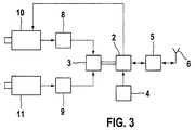
- Figure 3 die Monitoring device according to the invention with two cameras
- FIG. 4 the method according to the invention for Video surveillance.
- Video surveillance is used in many areas. Especially in public transport vehicles such as Buses and trains are used to increase the security of the Passengers monitoring devices to provide the hazards by people, fires and accidents and if necessary, send a message to a control center. Also monitoring different locations in a city has already been realized.
- the recorded image information is first in Pixels, i.e. pixels, divided. Then a discrete one Cosine transformation of the pixels made.
- the discrete cosine transform helps to get the pixels in Groups of pixels of different meanings split up.
- a subsequent quantization of the transformed pixels leads to curves that lead to a irreversible data loss.
- the quantized data are then binary coded.
- MPEG processes are characterized by the fact that a Data stream of images and image sequences in a bit stream of Features is implemented.
- the characteristics are of the Amount of data significantly less than the original Data stream, so there is a compression.
- the Features are chosen such that the eye and the ear perceive no significant differences.
- the Reverse transformation as from the characteristics again The data stream of images or image sequences are given by the MPEG process on.
- a monitoring device uses a video surveillance technique that Image sequences and individual images separate coding methods used, the individual images at selectable intervals be encoded.
- Image sequences and individual images separate coding methods used, the individual images at selectable intervals be encoded.
- a camera 1 is used as an imaging device via a first data input / output of a processor 2 connected. Via a second data input / output Processor 2 connected to a memory 3. About one Data input, the processor 2 is connected to a clock 4. The processor 2 is on via a third data input / output a transmitting / receiving station 5 connected. At one second data input / output of the transmitting / receiving station 5 an antenna 6 connected.
- the camera 1 here is a video camera that is used for monitoring a room or an area is used. It is but also a thermal imaging camera as an imaging device possible, which then picks up emissions in the infrared range and especially for the detection of heat sources like it Living things but also fire and apparatus with heat loss are suitable.
- the camera 1 has electronics that digitized the recorded image signals. Alternative is a digital camera possible.
- the resulting digital Data stream is transmitted to processor 2.
- the processor 2 uses the memory 3 to process the image signals Buffer image signals because the processor 2 Coded image signals.
- Such encoding is source encoding here Redundancy from the image signals from the camera 1.
- Image sequences become one with a first procedure here Coded MPEG method. MPEG procedures lead to a low resolution of the then stored image signals.
- Processor 2 encodes individual images with a second one Process, here a JPEG process.
- the coded Image signals are then stored in memory 3 and with provided with a time stamp, which is generated by means of the clock 4 becomes.
- Processor 1 carries out the coding of the individual images after a predetermined period of time, e.g. every 15 Seconds. The time period indicates with what accuracy a scene is monitored and what computing power and Memory requirements require this. After a given time overwrites the processor 2 stored image signals in Memory 3 with newly encoded image signals.
- the processor 2 also carries out an image analysis.
- the Image analysis is carried out using reference images, by means of which objects in the recorded image signals can be recognized. This comparison is based on the encoded image signals performed.
- a correlation method is used for a comparison, whereby a correlation coefficient is calculated, which then with a threshold value is compared. Is the Correlation coefficient above the threshold, then one Match detected. Is the correlation coefficient below the threshold, then there is no match recognized. If an object is recognized, it becomes one Control center reported.
- the processor 2 transmits one for this Message with the recognized object to the sending / receiving station 5, which uses the antenna 6 sent. Instead of via radio, the message can also be sent via a Line are transmitted, e.g. over the telephone network.
- the antenna 6 uses a modem that sends the message over the line transmits.
- Other means of communication are a siren or a lamp that connects directly to the processor 2 Signal processing are connected. They are considered Notification device called.
- the memory 3 has a for the recorded image signals rewritable memory with appropriate access time on.
- the reference image signals are not in one writable memory is stored, e.g. a CD-ROM is. Alternatively, however, the reference image signals even in a specially protected area of the rewritable memory.
- the processor 2 uses the clock 4 to recognize when to code individual images are.
- the monitoring device according to the invention is shown in FIG shown, with single images and still images of separate signal processors are encoded.
- the camera 1 is connected to a branch via a data output 7 connected.
- processor 2 is connected to a second data input Branch 7, processor 2 is connected.
- About one first data output of branch 7 is a Still image processor 8 connected to branch 7.
- Via a second data output of branch 7 is a Moving image processor 9 connected.
- a data output of the Still image processor 8 leads to a first data input of the Memory 3.
- a second data input of memory 3 is connected to the moving image processor 9.
- About a first The data input / output of processor 2 is memory 3 connected.
- the transmitting / receiving station 5 is connected.
- the antenna 6 is via the second data input / output Transmitting / receiving station 5 to this transmitting / receiving station 5 connected.
- the camera 1 delivers digital image signals as above shown to branch 7.
- Branch 7 is a electronic switch operated by the processor 2 becomes. With the switch the digital image signals to either the still image processor 8 or the Moving image processor 9 directed. It depends on when a still image is to be encoded from the image signals. In these time data are stored in the memory 3, which the Processor 2 then sets by means of the clock 4. During the So most of the time switch 7 becomes digital Image signals from the camera 1 to the moving image processor 9 redirect.
- the moving image processor 9 is a signal processor, which is designed for MPEG coding. So that leads Moving image processor 9 optimally through the MPEG coding. The The moving image processor 9 then stores coded data in the Memory 3 from.
- a still picture If a still picture is to be coded, then it directs the switch 7 to a signal from the processor 2 the digital Data stream to the still image processor 8, which the digital Image signals encoded using a JPEG method so that a high-resolution image is created. Also the Still image processor 8 then stores the encoded Image signals in the memory 3.
- the digital image signals from the camera 1 are encoded here in frames, the Switch 7 from the processor 2 depending on the Frame is switched so that only whole frames to the Still image processor 8 or moving image processor 9 be transmitted.
- the moving image processor 9 and the Still image processor 8 overwrite according to a predetermined one Time-coded coded image signals with new coded ones Image signals.
- the processor 2 carries out an image analysis of the stored ones Image signals using reference image signals as above represented by.
- the processor detects 2 objects in the stored image signals, then the Processor 2 this by means of the transceiver station 5 and the antenna 6 as a means of communication of a control center.
- the Switch 7, the still processor 8 and the Moving image processor 9 can collectively on one card be realized, which is inserted into a computer, wherein camera 1 is connected to the card.
- the Still picture processor 8 and moving picture processor 9 can also implemented on the processor 2 as software modules his. Here, however, the two processors are each as a separate signal processor is available. Use too a single processor for both tasks is possible.
- the monitoring device is shown in FIG shown, two cameras are used here.
- a Camera is used for shooting picture sequences especially for Moving images are used, and another camera is used for the Still images used.
- a still camera 10 is to the still image processor 8 via a data input of the still processor 8 connected.
- the Still image processor 8 provides signals to a first one Data input of the memory 3.
- a moving picture camera 11 is to a data input of the moving image processor 9 connected.
- To a second data input of the memory 3 the moving image processor 9 is connected.
- the first data input / output of processor 2 is the memory 3 connected.
- the clock 4 is connected to the processor 2.
- the processor 2 is via its second data input / output connected to the transceiver station 5.
- About your The second data input / output is the transceiver station 5 connected to the antenna 6.
- Via a data output of the Processor 2 the still camera 10 is connected.
- the processor 2 controls the camera via its data output 10, so that the still camera 10 only then image signals picks up when the processor 2 gives the signal.
- the Still picture signals are then sent to the still picture processor 8 which is transferred using a JPEG process Still picture signals are encoded and then stored in memory 3.
- the moving image camera 11 continuously delivers image signals to the Moving image processor 9, the MPEG coding to the Performs moving picture signals.
- the moving image processor 9 then writes the coded image signals into the memory 3.
- processor 2 inserts the stored one encoded image signals to a time stamp, which by means of Clock 4 is determined and on the other hand, the processor 2 as shown above, an image analysis using Through reference image signals to in the case of detected Objects using the means of communication of the Transmit / receive station 5 and the antenna 6. Also here the transmitting / receiving station 5 and the antenna 6 be replaced by a modem if a wired Communication connection exists.
- process step 12 begins the process according to the invention.
- process step 13 by means of an imaging device of a camera, as shown above, image signals recorded and from the Digitized camera.
- process step 14 determined whether a moving image should be saved or not. If this is the case, then in process step 15 MPEG coding carried out with low resolution.
- the encoded are then in method step 17 Image signals saved. However, a still image should be encoded then in step 16 instead of Step 15 performed a JPEG encoding to then the encoded image signals according to JPEG in Store step 17.
- a time stamp is added to the stored data.
- an image analysis is carried out using Reference image signals carried to objects in the to recognize stored image signals.
- Method step 20 then becomes this comparison carried out.
- method step 21 it is determined whether there is a match or not. As above a correlation coefficient is shown used. If there is a match, then in Method step 22 a message to a control center sent. The procedure then ends in Step 22. Will not match determined, then the process ends in process step 23.
- the method according to the invention or the one according to the invention Monitoring device is advantageously in Public transport vehicles used to to significantly increase security there. In these Vehicles will count the number of cameras per vehicle typically between four and six.
Applications Claiming Priority (2)
| Application Number | Priority Date | Filing Date | Title |
|---|---|---|---|
| DE2000118157 DE10018157A1 (de) | 2000-04-12 | 2000-04-12 | Überwachungseinrichtung |
| DE10018157 | 2000-04-12 |
Publications (2)
| Publication Number | Publication Date |
|---|---|
| EP1148726A2 true EP1148726A2 (fr) | 2001-10-24 |
| EP1148726A3 EP1148726A3 (fr) | 2002-03-27 |
Family
ID=7638488
Family Applications (1)
| Application Number | Title | Priority Date | Filing Date |
|---|---|---|---|
| EP01108783A Ceased EP1148726A3 (fr) | 2000-04-12 | 2001-04-07 | Dispositif de surveillance |
Country Status (2)
| Country | Link |
|---|---|
| EP (1) | EP1148726A3 (fr) |
| DE (1) | DE10018157A1 (fr) |
Cited By (8)
| Publication number | Priority date | Publication date | Assignee | Title |
|---|---|---|---|---|
| WO2005041580A1 (fr) * | 2003-10-16 | 2005-05-06 | Deutsche Telekom Ag | Dispositif de surveillance comprenant des caméras vidéo |
| US9041803B2 (en) | 2006-03-07 | 2015-05-26 | Coban Technologies, Inc. | Method for video/audio recording using multiple resolutions |
| US9225527B1 (en) | 2014-08-29 | 2015-12-29 | Coban Technologies, Inc. | Hidden plug-in storage drive for data integrity |
| US9307317B2 (en) | 2014-08-29 | 2016-04-05 | Coban Technologies, Inc. | Wireless programmable microphone apparatus and system for integrated surveillance system devices |
| US10152859B2 (en) | 2016-05-09 | 2018-12-11 | Coban Technologies, Inc. | Systems, apparatuses and methods for multiplexing and synchronizing audio recordings |
| US10165171B2 (en) | 2016-01-22 | 2018-12-25 | Coban Technologies, Inc. | Systems, apparatuses, and methods for controlling audiovisual apparatuses |
| US10370102B2 (en) | 2016-05-09 | 2019-08-06 | Coban Technologies, Inc. | Systems, apparatuses and methods for unmanned aerial vehicle |
| US10789840B2 (en) | 2016-05-09 | 2020-09-29 | Coban Technologies, Inc. | Systems, apparatuses and methods for detecting driving behavior and triggering actions based on detected driving behavior |
Families Citing this family (2)
| Publication number | Priority date | Publication date | Assignee | Title |
|---|---|---|---|---|
| DE10260483A1 (de) * | 2002-12-21 | 2004-07-15 | Rheinmetall Landsysteme Gmbh | Optronisches Sicht- bzw. Beobachtungsmittel |
| DE102004040941A1 (de) * | 2004-08-24 | 2006-03-09 | Macrosystem Digital Video Ag | Bildgebende Sicherheitsüberwachungsvorrichtung |
Citations (7)
| Publication number | Priority date | Publication date | Assignee | Title |
|---|---|---|---|---|
| JPH0795566A (ja) * | 1993-09-21 | 1995-04-07 | Nippon Telegr & Teleph Corp <Ntt> | 画像符号化方法および装置 |
| US5581297A (en) * | 1992-07-24 | 1996-12-03 | Intelligent Instruments Corporation | Low power video security monitoring system |
| DE19735254A1 (de) * | 1997-08-14 | 1999-02-18 | Cohausz Helge B | Vorrichtung zum Aufzeichnen von Bildinformationen von Ereignissen vor einem fahrenden Kraftfahrzeug |
| DE19829888A1 (de) * | 1998-07-05 | 2000-01-13 | Helmut Hochstatter | Raumüberwachung mit CCD-Technik |
| EP0979009A2 (fr) * | 1998-08-05 | 2000-02-09 | Matsushita Electronics Corporation | Système, appareil et caméra de surveillance et de télésurveillance |
| JP2000050263A (ja) * | 1998-07-28 | 2000-02-18 | Hitachi Ltd | 画像符号化並びに復号化装置及びこれを用いた撮像装置 |
| US6038257A (en) * | 1997-03-12 | 2000-03-14 | Telefonaktiebolaget L M Ericsson | Motion and still video picture transmission and display |
Family Cites Families (4)
| Publication number | Priority date | Publication date | Assignee | Title |
|---|---|---|---|---|
| US5724475A (en) * | 1995-05-18 | 1998-03-03 | Kirsten; Jeff P. | Compressed digital video reload and playback system |
| DE19722094A1 (de) * | 1996-12-10 | 1998-12-03 | Dag Auerbach | Datenminimierung für Überwachungsanlagen |
| EP0967584B1 (fr) * | 1998-04-30 | 2004-10-20 | Texas Instruments Incorporated | Système automatique de surveillance vidéo |
| SE522856C2 (sv) * | 1999-01-29 | 2004-03-09 | Axis Ab | En datalagrings- och reduceringsmetod för digitala bilder, samt ett övervakningssystem som använder nämnda metod |
-
2000
- 2000-04-12 DE DE2000118157 patent/DE10018157A1/de not_active Ceased
-
2001
- 2001-04-07 EP EP01108783A patent/EP1148726A3/fr not_active Ceased
Patent Citations (7)
| Publication number | Priority date | Publication date | Assignee | Title |
|---|---|---|---|---|
| US5581297A (en) * | 1992-07-24 | 1996-12-03 | Intelligent Instruments Corporation | Low power video security monitoring system |
| JPH0795566A (ja) * | 1993-09-21 | 1995-04-07 | Nippon Telegr & Teleph Corp <Ntt> | 画像符号化方法および装置 |
| US6038257A (en) * | 1997-03-12 | 2000-03-14 | Telefonaktiebolaget L M Ericsson | Motion and still video picture transmission and display |
| DE19735254A1 (de) * | 1997-08-14 | 1999-02-18 | Cohausz Helge B | Vorrichtung zum Aufzeichnen von Bildinformationen von Ereignissen vor einem fahrenden Kraftfahrzeug |
| DE19829888A1 (de) * | 1998-07-05 | 2000-01-13 | Helmut Hochstatter | Raumüberwachung mit CCD-Technik |
| JP2000050263A (ja) * | 1998-07-28 | 2000-02-18 | Hitachi Ltd | 画像符号化並びに復号化装置及びこれを用いた撮像装置 |
| EP0979009A2 (fr) * | 1998-08-05 | 2000-02-09 | Matsushita Electronics Corporation | Système, appareil et caméra de surveillance et de télésurveillance |
Non-Patent Citations (2)
| Title |
|---|
| PATENT ABSTRACTS OF JAPAN vol. 1995, no. 07, 31. August 1995 (1995-08-31) & JP 07 095566 A (NIPPON TELEGR & TELEPH CORP), 7. April 1995 (1995-04-07) * |
| PATENT ABSTRACTS OF JAPAN vol. 2000, no. 05, 14. September 2000 (2000-09-14) & JP 2000 050263 A (HITACHI LTD), 18. Februar 2000 (2000-02-18) * |
Cited By (9)
| Publication number | Priority date | Publication date | Assignee | Title |
|---|---|---|---|---|
| WO2005041580A1 (fr) * | 2003-10-16 | 2005-05-06 | Deutsche Telekom Ag | Dispositif de surveillance comprenant des caméras vidéo |
| US9041803B2 (en) | 2006-03-07 | 2015-05-26 | Coban Technologies, Inc. | Method for video/audio recording using multiple resolutions |
| US9225527B1 (en) | 2014-08-29 | 2015-12-29 | Coban Technologies, Inc. | Hidden plug-in storage drive for data integrity |
| US9307317B2 (en) | 2014-08-29 | 2016-04-05 | Coban Technologies, Inc. | Wireless programmable microphone apparatus and system for integrated surveillance system devices |
| US10165171B2 (en) | 2016-01-22 | 2018-12-25 | Coban Technologies, Inc. | Systems, apparatuses, and methods for controlling audiovisual apparatuses |
| US10152859B2 (en) | 2016-05-09 | 2018-12-11 | Coban Technologies, Inc. | Systems, apparatuses and methods for multiplexing and synchronizing audio recordings |
| US10152858B2 (en) | 2016-05-09 | 2018-12-11 | Coban Technologies, Inc. | Systems, apparatuses and methods for triggering actions based on data capture and characterization |
| US10370102B2 (en) | 2016-05-09 | 2019-08-06 | Coban Technologies, Inc. | Systems, apparatuses and methods for unmanned aerial vehicle |
| US10789840B2 (en) | 2016-05-09 | 2020-09-29 | Coban Technologies, Inc. | Systems, apparatuses and methods for detecting driving behavior and triggering actions based on detected driving behavior |
Also Published As
| Publication number | Publication date |
|---|---|
| DE10018157A1 (de) | 2001-10-18 |
| EP1148726A3 (fr) | 2002-03-27 |
Similar Documents
| Publication | Publication Date | Title |
|---|---|---|
| DE602005005583T2 (de) | Videoüberwachungssysteme im allgemeinen und speziell eine Vorrichtung und Verfahren zur automatischen Echtzeiterfassung abnormaler Bewegung in Videoströmen | |
| DE69630121T2 (de) | Bildkompressionssystem | |
| DE60005380T2 (de) | Überwachungssystem | |
| AU2021204819B2 (en) | Real-time data acquisition and recording system viewer | |
| DE102012215544A1 (de) | Überwachung einer Bahnstrecke | |
| EP1148726A2 (fr) | Dispositif de surveillance | |
| DE202015102381U1 (de) | Mobiles Echtzeit-Videoaufzeichnungsgerät | |
| DE3029190A1 (de) | Pseudobewegtbilduebertragungssystem | |
| CN107231547B (zh) | 视频监控系统和方法 | |
| DE19848490B4 (de) | Bildinformationsübertragungsverfahren und -vorrichtung | |
| DE10146821B4 (de) | Zutrittskontrollsystem | |
| EP1877934A1 (fr) | Procede et systeme de traitement de donnees | |
| EP0336510B1 (fr) | Codeur predictif d'image immobile | |
| DE19749655B4 (de) | Verfahren und Vorrichtung zum Kodieren eines Bewegungsvektors | |
| DE102005053148A1 (de) | Verfahren zur Handhabung von Inhaltsinformationen | |
| DE102020128517A1 (de) | Fahrzeug-Fahrzeug-Sicherheit | |
| EP1762994A1 (fr) | Caméra de télésurveillance inteligente | |
| EP2462557B1 (fr) | Procédé d'analyse vidéo | |
| EP1254567A1 (fr) | Procede et dispositif permettant de detecter des erreurs dans des systemes de traitement de signal faisant partie du domaine de la securite | |
| CN214225705U (zh) | 5g可视化智能ai音视频调度指挥系统 | |
| CN106603975A (zh) | 监控视频的显示方法、装置和系统 | |
| DE102021207643A1 (de) | Überwachungsanordnung und Verfahren zur Überwachung | |
| DE4425567A1 (de) | Verfahren zur interaktiven Informationsübertragung | |
| DE102020134448A1 (de) | Sicherheitsvorrichtung und Verfahren zur sicheren Übertragung von digitalen Daten | |
| DE10357411A1 (de) | Zugangskontrollsystem sowie Verfahren zum Betreiben desselben |
Legal Events
| Date | Code | Title | Description |
|---|---|---|---|
| PUAI | Public reference made under article 153(3) epc to a published international application that has entered the european phase |
Free format text: ORIGINAL CODE: 0009012 |
|
| AK | Designated contracting states |
Kind code of ref document: A2 Designated state(s): BE DE FR SE Kind code of ref document: A2 Designated state(s): AT BE CH CY DE DK ES FI FR GB GR IE IT LI LU MC NL PT SE TR |
|
| AX | Request for extension of the european patent |
Free format text: AL;LT;LV;MK;RO;SI |
|
| PUAL | Search report despatched |
Free format text: ORIGINAL CODE: 0009013 |
|
| AK | Designated contracting states |
Kind code of ref document: A3 Designated state(s): AT BE CH CY DE DK ES FI FR GB GR IE IT LI LU MC NL PT SE TR |
|
| AX | Request for extension of the european patent |
Free format text: AL;LT;LV;MK;RO;SI |
|
| RIC1 | Information provided on ipc code assigned before grant |
Free format text: 7H 04N 7/18 A, 7H 04N 7/36 B |
|
| 17P | Request for examination filed |
Effective date: 20020927 |
|
| AKX | Designation fees paid |
Free format text: BE DE FR SE |
|
| 17Q | First examination report despatched |
Effective date: 20060712 |
|
| STAA | Information on the status of an ep patent application or granted ep patent |
Free format text: STATUS: THE APPLICATION HAS BEEN REFUSED |
|
| 18R | Application refused |
Effective date: 20100920 |