EP1148365A2 - Anordnung mehrerer Ferrulen für Lichtwellenleiter und Verfahren zum Herstellen eines Kunststoff-Ferrulen aufweisenden Bandes - Google Patents
Anordnung mehrerer Ferrulen für Lichtwellenleiter und Verfahren zum Herstellen eines Kunststoff-Ferrulen aufweisenden Bandes Download PDFInfo
- Publication number
- EP1148365A2 EP1148365A2 EP01107331A EP01107331A EP1148365A2 EP 1148365 A2 EP1148365 A2 EP 1148365A2 EP 01107331 A EP01107331 A EP 01107331A EP 01107331 A EP01107331 A EP 01107331A EP 1148365 A2 EP1148365 A2 EP 1148365A2
- Authority
- EP
- European Patent Office
- Prior art keywords
- ferrules
- band
- plastic
- arrangement according
- arrangement
- Prior art date
- Legal status (The legal status is an assumption and is not a legal conclusion. Google has not performed a legal analysis and makes no representation as to the accuracy of the status listed.)
- Withdrawn
Links
- 238000000034 method Methods 0.000 title claims description 10
- 238000004519 manufacturing process Methods 0.000 title claims description 7
- 239000013307 optical fiber Substances 0.000 claims description 8
- 238000001746 injection moulding Methods 0.000 claims description 4
- 238000002347 injection Methods 0.000 claims description 3
- 239000007924 injection Substances 0.000 claims description 3
- 238000000465 moulding Methods 0.000 description 4
- 230000008569 process Effects 0.000 description 4
- 239000000463 material Substances 0.000 description 3
- 239000000835 fiber Substances 0.000 description 2
- 230000003287 optical effect Effects 0.000 description 2
- 238000005452 bending Methods 0.000 description 1
- 230000005540 biological transmission Effects 0.000 description 1
- 239000013590 bulk material Substances 0.000 description 1
- 150000001875 compounds Chemical class 0.000 description 1
- 230000008878 coupling Effects 0.000 description 1
- 238000010168 coupling process Methods 0.000 description 1
- 238000005859 coupling reaction Methods 0.000 description 1
- 239000011521 glass Substances 0.000 description 1
- 238000012805 post-processing Methods 0.000 description 1
- 230000009467 reduction Effects 0.000 description 1
- 238000000926 separation method Methods 0.000 description 1
- 238000007711 solidification Methods 0.000 description 1
- 230000008023 solidification Effects 0.000 description 1
- 239000000243 solution Substances 0.000 description 1
- 239000007921 spray Substances 0.000 description 1
- 238000005507 spraying Methods 0.000 description 1
- 230000007480 spreading Effects 0.000 description 1
- 238000003892 spreading Methods 0.000 description 1
Images

Classifications
-
- G—PHYSICS
- G02—OPTICS
- G02B—OPTICAL ELEMENTS, SYSTEMS OR APPARATUS
- G02B6/00—Light guides; Structural details of arrangements comprising light guides and other optical elements, e.g. couplings
- G02B6/24—Coupling light guides
- G02B6/36—Mechanical coupling means
- G02B6/38—Mechanical coupling means having fibre to fibre mating means
- G02B6/3807—Dismountable connectors, i.e. comprising plugs
- G02B6/3833—Details of mounting fibres in ferrules; Assembly methods; Manufacture
- G02B6/3865—Details of mounting fibres in ferrules; Assembly methods; Manufacture fabricated by using moulding techniques
-
- G—PHYSICS
- G02—OPTICS
- G02B—OPTICAL ELEMENTS, SYSTEMS OR APPARATUS
- G02B6/00—Light guides; Structural details of arrangements comprising light guides and other optical elements, e.g. couplings
- G02B6/24—Coupling light guides
- G02B6/36—Mechanical coupling means
- G02B6/38—Mechanical coupling means having fibre to fibre mating means
- G02B6/3807—Dismountable connectors, i.e. comprising plugs
- G02B6/3873—Connectors using guide surfaces for aligning ferrule ends, e.g. tubes, sleeves, V-grooves, rods, pins, balls
- G02B6/3874—Connectors using guide surfaces for aligning ferrule ends, e.g. tubes, sleeves, V-grooves, rods, pins, balls using tubes, sleeves to align ferrules
- G02B6/3878—Connectors using guide surfaces for aligning ferrule ends, e.g. tubes, sleeves, V-grooves, rods, pins, balls using tubes, sleeves to align ferrules comprising a plurality of ferrules, branching and break-out means
-
- Y—GENERAL TAGGING OF NEW TECHNOLOGICAL DEVELOPMENTS; GENERAL TAGGING OF CROSS-SECTIONAL TECHNOLOGIES SPANNING OVER SEVERAL SECTIONS OF THE IPC; TECHNICAL SUBJECTS COVERED BY FORMER USPC CROSS-REFERENCE ART COLLECTIONS [XRACs] AND DIGESTS
- Y10—TECHNICAL SUBJECTS COVERED BY FORMER USPC
- Y10S—TECHNICAL SUBJECTS COVERED BY FORMER USPC CROSS-REFERENCE ART COLLECTIONS [XRACs] AND DIGESTS
- Y10S439/00—Electrical connectors
- Y10S439/933—Special insulation
- Y10S439/937—Plural insulators in strip form
Definitions
- the invention relates to an arrangement of several ferrules for Optical waveguide and a method for producing a Band with plastic ferrules.
- the object of the invention is therefore to propose an arrangement so that the ferrules are fed to an assembly machine can be without complex separating and feeding devices are necessary.
- This problem is solved by arranging several ferrules for optical fibers with at least one connecting section, whereby through the at least one connecting section at least two ferrules are connected to one another.
- the task is solved by arranging several Ferrules for optical fibers, the ferrules on arranged in a continuous band and fixed on this are.
- ferrules By connecting ferrules to a band is a simple one Possibility to assemble the ferrules feed. Depending on the design of the arrangement, only the position the ferrules set on or in the band, where the ferrules can be held with a game, or else twisting of the ferrules is also prevented.
- the method is advantageous because in the same manufacturing step both the plastic ferrule and the band are made can be. Because no additional manufacturing step is necessary, the inventive method performs to significant cost savings.
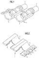
- FIG 1 there are two band segments 4 of a band 1 with it molded ferrules 2 shown.
- the ferrules 2 are in one piece connected with band segments 1, but can be relative simply be separated from the tape, because at the connection points between the ferrules 2 and the band 1 cross-sectional reductions are provided.
- the band segments 4 are U-shaped designed. This design opens up advantages in Manufacturing process.
- the ferrules 2 are during the spraying process sprayed around a mold core after the solidification the plastic material is pulled out again. A flat one Tape would hinder the core pull.
- the band segments 4 are without the ferrules 2 shown.
- the Connection sections 3 a significantly smaller cross section have than the adjacent sections. The separation is very easy. Because the tape 1 is shaped by the U. Sections, however, is safe Keeping the tape guaranteed.
- Forming sections 5 of the band segments 4, which is used to inject a further band segment 4 are provided, have a so-called undercut geometry on. When molding a new belt segment 4 on Existing creates a cold spray seam, which is a potential Represents crack. The holes 6 in the molding section 5 when molding plastic material enforced, so that there is a "locking" between the old Band segment and the newly molded band segment results.
- the Forming section 5 in the embodiment of Figure 2 is three parts, the middle part compared to the two adjacent parts is offset. This is in again Figure 3 clearly recognizable.
- This cross section is next to that Forming section 5 also plastic injection molding 7 the newly molded To recognize band segment.
- the molding compound 7 of the new Band segment extends through the bores of the forming section 5.
- the holes are each conical, so that a secure hold between the forming section 5 and the new band segment results, and the two parts are neither can separate from each other upwards or downwards.
- the safe one and stable connection between two band segments 4 is important because tapes are usually wound on rolls become. This means that the belt is subject to bending and is therefore exposed to a special load.
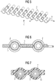
- FIG. 5 shows how a large number of band segments 4 are connected Ferrules 2 forms a band 1.
- the band 1 When fed into a machine the band 1 is moved in the direction of arrow 9. From the first Band segment is already removed the ferrule. The removal the ferrules from the tape 1 can through the assembly machine happen.
- the holding tools can be used for holding during assembly with an optical fiber at the same time as a tool for releasing the ferrules from the band serve.
- Figure 6 shows a longitudinal section through the tape with still ferrules 2 located therein. The thin ones are clearly visible Connecting bridges 3. It is as clear as the two shown band segments merge.
- the Ferrules are connected directly to each other.
- the ferrules are then no longer connected to the belt in one piece, but have a connecting section that the ferrules connects with each other.
- the problem with this simplified Arrangement is the stability of the entire band. Farther it is conceivable that the ferrules are not in one piece with the band are connected, but arranged on this by clamping are.
- the clamping can be done without play or so, that the ferrules can still rotate, for example.
- the Clamping can be realized according to Figure 7, where the tape from there is a lower band 10 and an upper band 11.
- the ferrules 2 are added between the two bands 10 and 11 and held. The removal from the tape takes place in this Fall by spreading the two bands or by pushing them out on a hinge side.
Landscapes
- Physics & Mathematics (AREA)
- General Physics & Mathematics (AREA)
- Optics & Photonics (AREA)
- Mechanical Coupling Of Light Guides (AREA)
Abstract
Description
- Spritzen einer ersten Kunststoff-Ferrule,
- Weitertransport der fertigen Kunststoff-Ferrule um eine definierte Wegstrecke, und
- Spritzen einer zweiten Kunststoff-Ferrule, so daß sie mit der ersten Kunststoff-Ferrule verbunden ist.
- Figur 1
- zwei einstückig mit einem Band verbundene KunststoffFerrulen,
- Figur 2
- zwei Bandsegmente des Bandes von Figur 1,
- Figur 3
- die Anformgeometrie eines Bandsegmentes von Figur 2,
- Figur 4
- die Anordnung von Figur 1 in einer Draufsicht,
- Figur 5
- die Anordnung von Figur 1 mit einer Vielzahl von Ferrulen,
- Figur 6
- einen Querschnitt der Anordnung von Figur 1 und
- Figur 7
- ein weiteres Ausführungsbeispieles einer Anordnung mit Ferrulen und einem Band.
Claims (14)
- Anordnung mehrerer Ferrulen für Lichtwellenleiter mit mindestens einem Verbindungsabschnitt (3),
wobei durch den mindestens einen Verbindungsabschnitt (3) mindestens zwei Ferrulen (2) miteinander verbunden sind. - Anordnung nach Anspruch 1,
dadurch gekennzeichnet, daß eine Vielzahl miteinander verbundener Ferrulen (2) ein Band (1) bilden. - Anordnung nach Anspruch 1,
dadurch gekennzeichnet, daß die Verbindungsabschnitte (3) flexibel sind. - Anordnung nach Anspruch 1,
dadurch gekennzeichnet, daß der mindestens eine Verbindungsabschnitt (3) einen Abschnitt mit verringertem Querschnitt aufweist. - Anordnung mehrerer Ferrulen für Lichtwellenleiter
mit einem fortlaufenden Band (1), wobei die Ferrulen (2) auf dem Band (1) angeordnet und fixiert sind. - Anordnung nach Anspruch 5,
dadurch gekennzeichnet, daß das fortlaufende Band (1) ein Kunststoffspritzteil ist. - Anordnung nach Anspruch 6,
dadurch gekennzeichnet, daß ein Bandsegment (4) zum Anspritzen eines weiteren Bandsegmentes (4) eine Geometrie aufweist, durch die die zwei Bandsegmente (4) verrastet sind. - Anordnung nach Anspruch 5,
dadurch gekennzeichnet, daß die Kunststoff-Ferrulen (2) mit dem Band (1) einstükkig verbunden sind. - Anordnung nach Anspruch 8,
dadurch gekennzeichnet, daß die Ferrulen (2) und das Band (1) an einem Endbereich der Ferrule miteinander verbunden sind. - Anordnung nach Anspruch 5,
dadurch gekennzeichnet, daß das Band (1) durch miteinander verbundene U-förmige Brückensegmente gebildet ist. - Anordnung nach Anspruch 5,
dadurch gekennzeichnet, daß das Band (1) aus einem Ober- und einem Unterband (10, 11) besteht, zwischen denen die Kunststoff-Ferrulen (2) aufgenommen sind. - Anordnung nach Anspruch 5,
dadurch gekennzeichnet, daß die Kunststoff-Ferrulen (2) derart auf dem Band (1) fixiert sind, daß sie um ihre Längsachse drehbar sind. - Verfahren zum Herstellen eines Kunststoff-Ferrulen (2) aufweisenden Bandes (1) mit folgenden Verfahrensschritten:Spritzen einer ersten Kunststoff-Ferrule (2),Weitertransport der fertigen Kunststoff-Ferrule (2) um eine definierte Wegstrecke undSpritzen einer zweiten Kunststoff-Ferrule (2), so daß sie mit der ersten Kunststoff-Ferrule verbunden ist.
- Verfahren nach Anspruch 13,
dadurch gekennzeichnet, daß mit den Kunststoff-Ferrulen ein Bandsegment (4) gespritzt wird, wobei die Verbindung der Ferrulen (2) über die Bandsegmente (4) erfolgt.
Applications Claiming Priority (2)
| Application Number | Priority Date | Filing Date | Title |
|---|---|---|---|
| DE10019392 | 2000-04-19 | ||
| DE10019392A DE10019392A1 (de) | 2000-04-19 | 2000-04-19 | Anordnung mehrerer Ferrulen für Lichtwellenleiter und Verfahren zum Herstellen eines Kunststoff-Ferrulen aufweisenden Bandes |
Publications (2)
| Publication Number | Publication Date |
|---|---|
| EP1148365A2 true EP1148365A2 (de) | 2001-10-24 |
| EP1148365A3 EP1148365A3 (de) | 2002-02-13 |
Family
ID=7639311
Family Applications (1)
| Application Number | Title | Priority Date | Filing Date |
|---|---|---|---|
| EP01107331A Withdrawn EP1148365A3 (de) | 2000-04-19 | 2001-03-24 | Anordnung mehrerer Ferrulen für Lichtwellenleiter und Verfahren zum Herstellen eines Kunststoff-Ferrulen aufweisenden Bandes |
Country Status (4)
| Country | Link |
|---|---|
| US (1) | US6877907B2 (de) |
| EP (1) | EP1148365A3 (de) |
| JP (1) | JP2001350054A (de) |
| DE (1) | DE10019392A1 (de) |
Families Citing this family (1)
| Publication number | Priority date | Publication date | Assignee | Title |
|---|---|---|---|---|
| JP4783212B2 (ja) | 2006-06-02 | 2011-09-28 | 矢崎総業株式会社 | 連鎖状フェルール |
Family Cites Families (9)
| Publication number | Priority date | Publication date | Assignee | Title |
|---|---|---|---|---|
| US3797107A (en) * | 1972-12-07 | 1974-03-19 | Itt | Backplane manufacture |
| US3901575A (en) * | 1973-11-26 | 1975-08-26 | Amp Inc | Plug for patch systems |
| DE3119020C2 (de) * | 1980-08-09 | 1985-05-09 | Nichifu Terminal Industries Co., Ltd., Osaka | Verfahren zur Herstellung eines Verbinderteils zwischen zwei Klemmensätzen |
| US4400874A (en) * | 1981-07-30 | 1983-08-30 | Western Electric Company | Wiring connector plugs to produce a wire mult |
| US4464817A (en) * | 1982-05-24 | 1984-08-14 | Amp Incorporated | Optical waveguide terminating apparatus |
| DE3572132D1 (en) * | 1984-08-15 | 1989-09-14 | Terry Ernest Francis | Automatic nailer system |
| DE3809038A1 (de) | 1988-03-15 | 1989-09-28 | Siemens Ag | Verfahren zum herstellen von lichtwellenleiterverbindungen |
| DE3809037A1 (de) | 1988-03-15 | 1989-09-28 | Siemens Ag | Magazinierter lichtwellenleiter-verbinder |
| US5954539A (en) * | 1995-01-17 | 1999-09-21 | The Whitaker Corporation | Method of handling parts and structure therefor |
-
2000
- 2000-04-19 DE DE10019392A patent/DE10019392A1/de not_active Withdrawn
-
2001
- 2001-03-24 EP EP01107331A patent/EP1148365A3/de not_active Withdrawn
- 2001-04-18 JP JP2001119792A patent/JP2001350054A/ja active Pending
- 2001-04-19 US US09/837,610 patent/US6877907B2/en not_active Expired - Fee Related
Non-Patent Citations (1)
| Title |
|---|
| None * |
Also Published As
| Publication number | Publication date |
|---|---|
| US6877907B2 (en) | 2005-04-12 |
| US20020001438A1 (en) | 2002-01-03 |
| JP2001350054A (ja) | 2001-12-21 |
| EP1148365A3 (de) | 2002-02-13 |
| DE10019392A1 (de) | 2001-12-06 |
Similar Documents
| Publication | Publication Date | Title |
|---|---|---|
| DE3027087C2 (de) | Spritzgußvorrichtung sowie damit herstellbarer Sonnenenergiekollektor | |
| DE3119020C2 (de) | Verfahren zur Herstellung eines Verbinderteils zwischen zwei Klemmensätzen | |
| DE69319243T2 (de) | Verfahren und vorrichtung zum herstellen von thermoplastischen kunststoffschrauben | |
| EP0225846B1 (de) | Verfahren und Spritzwerkzeug zur Herstellung eines Kunststoff-Gliederbandes, insbesondere einer Kugelkette | |
| DE102008029104B3 (de) | Verfahren zur Herstellung eines mehrteiligen Hybridbauteils | |
| EP3678777B1 (de) | Verfahren zur herstellung eines napfstreifens | |
| EP0236712B1 (de) | Verfahren zum positionsgerechten Fügen von Lichtwellenleitern in Koppelstellen und Koppelelement für Lichtwellenleiter-Schalter | |
| DE60114214T2 (de) | Verfahren zur herstellung einer zahnbürste | |
| DE102006036139A1 (de) | Spritzgießanordnung und Verfahren zum Anspritzen eines Formteils und Verwendung einer Spritzgießanordnung | |
| DE19515294B4 (de) | Bürstenherstellungsmaschine | |
| DE10019392A1 (de) | Anordnung mehrerer Ferrulen für Lichtwellenleiter und Verfahren zum Herstellen eines Kunststoff-Ferrulen aufweisenden Bandes | |
| DE4211677A1 (de) | Lichtwellenleiterverbinder | |
| EP0398389A2 (de) | Sprühkopf einer Sprühvorrichtung zum Aufsprühen von Flüssigkeiten, insbesondere Trennmitteln | |
| EP0483492B1 (de) | Stationärer Formträger an einer Kunststoff-Spritzgiessmaschine | |
| DE2625531C3 (de) | Vorrichtung zum Herstellen eines Fertigteiles durch Anspritzen eines flächigen Rohteils mit Kunststoff in einer Spritzgießform | |
| DE4310943C1 (de) | Verfahren zur Herstellung eines Gurtbands und Gurtbandabschnitt | |
| EP0853812B1 (de) | Verfahren und vorrichtung zur endmontage einer computer-tastatur | |
| DE19918776A1 (de) | Formwerkzeug zur Herstellung von mehreren montagegespritzten Bauteilen | |
| DE2926008B2 (de) | Verbundformteil aus einer eine Vielzahl von vorgegebenen Durchgangsbohrungen aufweisenden Metallplatte und einem an diese in einer Spritzgießform angespritztes, einteiliges Formstück aus Kunststoff | |
| DE19916012B4 (de) | Verfahren zur Herstellung eines Kunststoffhosenbügels mit einem Spannelement | |
| EP0920979B1 (de) | Verfahren und Spritzgiessform zur Herstellung eines spritzgegossenen Bauelements | |
| DE4320524C2 (de) | Spritzgießmaschine | |
| DE10152967A1 (de) | Verfahren und Vorrichtung zum Herstellen eines mehrteiligen Kunststofferzeugnisses | |
| DE602004006846T2 (de) | Anlage und verfahren zur herstellung von produkten aus spritzguss-kunststoffkomponenten | |
| EP0061516B1 (de) | Verfahren zur Herstellung eines Koppelelementes zum Ein- und/oder Auskoppeln von Licht |
Legal Events
| Date | Code | Title | Description |
|---|---|---|---|
| PUAI | Public reference made under article 153(3) epc to a published international application that has entered the european phase |
Free format text: ORIGINAL CODE: 0009012 |
|
| AK | Designated contracting states |
Kind code of ref document: A2 Designated state(s): DE ES FR GB IT SE Kind code of ref document: A2 Designated state(s): AT BE CH CY DE DK ES FI FR GB GR IE IT LI LU MC NL PT SE TR |
|
| AX | Request for extension of the european patent |
Free format text: AL;LT;LV;MK;RO;SI |
|
| PUAL | Search report despatched |
Free format text: ORIGINAL CODE: 0009013 |
|
| AK | Designated contracting states |
Kind code of ref document: A3 Designated state(s): AT BE CH CY DE DK ES FI FR GB GR IE IT LI LU MC NL PT SE TR |
|
| AX | Request for extension of the european patent |
Free format text: AL;LT;LV;MK;RO;SI |
|
| 17P | Request for examination filed |
Effective date: 20020227 |
|
| 17Q | First examination report despatched |
Effective date: 20020820 |
|
| AKX | Designation fees paid |
Free format text: DE ES FR GB IT SE |
|
| 17Q | First examination report despatched |
Effective date: 20020820 |
|
| GRAP | Despatch of communication of intention to grant a patent |
Free format text: ORIGINAL CODE: EPIDOSNIGR1 |
|
| STAA | Information on the status of an ep patent application or granted ep patent |
Free format text: STATUS: THE APPLICATION IS DEEMED TO BE WITHDRAWN |
|
| 18D | Application deemed to be withdrawn |
Effective date: 20070623 |