EP1147993B1 - Scharnierartiges Verbindungsteil - Google Patents
Scharnierartiges Verbindungsteil Download PDFInfo
- Publication number
- EP1147993B1 EP1147993B1 EP20010109546 EP01109546A EP1147993B1 EP 1147993 B1 EP1147993 B1 EP 1147993B1 EP 20010109546 EP20010109546 EP 20010109546 EP 01109546 A EP01109546 A EP 01109546A EP 1147993 B1 EP1147993 B1 EP 1147993B1
- Authority
- EP
- European Patent Office
- Prior art keywords
- connecting part
- hinge
- transport container
- bracket
- lid
- Prior art date
- Legal status (The legal status is an assumption and is not a legal conclusion. Google has not performed a legal analysis and makes no representation as to the accuracy of the status listed.)
- Expired - Lifetime
Links
- 238000004873 anchoring Methods 0.000 description 4
- 238000001746 injection moulding Methods 0.000 description 2
- 239000000463 material Substances 0.000 description 2
- 238000004026 adhesive bonding Methods 0.000 description 1
- 239000003795 chemical substances by application Substances 0.000 description 1
- 230000001419 dependent effect Effects 0.000 description 1
- 230000001627 detrimental effect Effects 0.000 description 1
- 238000005516 engineering process Methods 0.000 description 1
- 238000007373 indentation Methods 0.000 description 1
- 238000003780 insertion Methods 0.000 description 1
- 230000037431 insertion Effects 0.000 description 1
- 238000004519 manufacturing process Methods 0.000 description 1
- 239000002184 metal Substances 0.000 description 1
- 238000010327 methods by industry Methods 0.000 description 1
- 230000035515 penetration Effects 0.000 description 1
- 238000004064 recycling Methods 0.000 description 1
- 238000006798 ring closing metathesis reaction Methods 0.000 description 1
- 238000007493 shaping process Methods 0.000 description 1
- 239000007787 solid Substances 0.000 description 1
- 238000007711 solidification Methods 0.000 description 1
- 230000008023 solidification Effects 0.000 description 1
- 239000000243 solution Substances 0.000 description 1
- 238000003860 storage Methods 0.000 description 1
- 238000003466 welding Methods 0.000 description 1
Images
Classifications
-
- B—PERFORMING OPERATIONS; TRANSPORTING
- B65—CONVEYING; PACKING; STORING; HANDLING THIN OR FILAMENTARY MATERIAL
- B65D—CONTAINERS FOR STORAGE OR TRANSPORT OF ARTICLES OR MATERIALS, e.g. BAGS, BARRELS, BOTTLES, BOXES, CANS, CARTONS, CRATES, DRUMS, JARS, TANKS, HOPPERS, FORWARDING CONTAINERS; ACCESSORIES, CLOSURES, OR FITTINGS THEREFOR; PACKAGING ELEMENTS; PACKAGES
- B65D43/00—Lids or covers for rigid or semi-rigid containers
- B65D43/14—Non-removable lids or covers
- B65D43/16—Non-removable lids or covers hinged for upward or downward movement
- B65D43/163—Non-removable lids or covers hinged for upward or downward movement the container and the lid being made separately
- B65D43/169—Non-removable lids or covers hinged for upward or downward movement the container and the lid being made separately the lid, the hinge and the element connecting them to the container being made of one piece
-
- B—PERFORMING OPERATIONS; TRANSPORTING
- B29—WORKING OF PLASTICS; WORKING OF SUBSTANCES IN A PLASTIC STATE IN GENERAL
- B29C—SHAPING OR JOINING OF PLASTICS; SHAPING OF MATERIAL IN A PLASTIC STATE, NOT OTHERWISE PROVIDED FOR; AFTER-TREATMENT OF THE SHAPED PRODUCTS, e.g. REPAIRING
- B29C45/00—Injection moulding, i.e. forcing the required volume of moulding material through a nozzle into a closed mould; Apparatus therefor
- B29C45/0081—Injection moulding, i.e. forcing the required volume of moulding material through a nozzle into a closed mould; Apparatus therefor of objects with parts connected by a thin section, e.g. hinge, tear line
-
- B—PERFORMING OPERATIONS; TRANSPORTING
- B29—WORKING OF PLASTICS; WORKING OF SUBSTANCES IN A PLASTIC STATE IN GENERAL
- B29L—INDEXING SCHEME ASSOCIATED WITH SUBCLASS B29C, RELATING TO PARTICULAR ARTICLES
- B29L2031/00—Other particular articles
- B29L2031/712—Containers; Packaging elements or accessories, Packages
Definitions
- the invention relates to a hinge-like connecting part between a cover and a transport container according to the preamble of patent claim 1.
- the publication GB-A-2 245 309 discloses a hinged connection element for the pivotable connection of parts of a collapsible plastic container.
- the connecting part is inserted in an opening of a side wall of the container and encloses both a hinge pin integrated in the hinged second container part as well as a part of the side wall and thereby holds the pivot pivotally fixed in a recess provided in the side wall.
- the document GB-A-1 241 992 teaches a hinge-like connection element for the pivotable mounting of a sun visor on a rod provided therefor.
- the portion surrounding the rod of the connecting element integrated with the sun visor has flexible portions, which are held together by means of a spring clip and thereby clamp the rod.
- hinge brackets are used, which are known in any form, such as rivets or bolts, fixed (see Example of a commercially available hinge bracket on page 35 Euro catalog 1999, Georg Utz AG, plastic Technology for storage and transport).
- hinge brackets for solidification of articulation sealable plastic container, is obvious.
- the use of different materials has a detrimental effect on the recycling of the container, since the small parts of the container made of metal are to be removed in advance.
- the object of the present invention is therefore to provide a simple and recyclable fastening device for a cover to a transport container, their mechanical stability is almost identical to that secured by a hinge clip articulated connection.
- the advantage of the invention lies in the use of a single component, which compared to the conventional mounting options of a support lid on a transport container, the function of a hinge under Ver zicht a hinge bracket takes over.
- Another advantage of the invention lies in the cost-effective production of the component by injection molding.
- design of the component with a series of saw teeth in the region of the front formed to a tab end advantageously to tune the ring width of the hinge-like connecting part to the dimensions of the objects to be crosslinked.
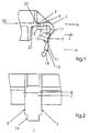
- FIG. 1 shows an embodiment of the hinge-like connecting part 1 according to the invention, in which the at least partially formed to a flexible flap 8 connecting part 1 is integrally attached to the abutting edge 22 of a support rim 21 of a lid 20.
- the part in the region of the upper edge of a side wall of a (not shown here) transport container.
- the connecting part 1 has at least partially flexible sections that allow a ring-like connection.
- the connecting part 1 has a rear straight portion 4, which is integrally connected to the abutting edge 22 of a lid 20 and is substantially rigid.
- a plug-in opening 5 Inserted in this section is a plug-in opening 5, in which the front free end 16 of the tab 8 engages in the closed state.
- an arcuate section 7 is provided in the middle part 9 of the connecting part 1 in the middle part 9 of the connecting part 1 .
- a trough-like depression 10 which is dimensioned so that the outwardly facing edges 12 of the lateral boundaries 11 abut each other in a ring closure of the connecting part 1 and thus give the connecting part a similar stability as a solid ring.
- the connecting part 1 may also be provided with a plurality of depressions of similar function, depending on the desired shape or possible additional functions.
- a further arcuate portion 13 is provided, which together with the aforementioned sections 4, 7 and 9, the annular shape of the connecting part 1 in the closed state (see. FIG. 3 ) completes.
- an anchoring part 14 is formed, which is hook-shaped and flattened in the front region for the penetration of the insertion opening 5.
- FIG. 2 shows that the formed to a flexible tab portion 8 of the connecting part has mutually parallel side walls 2. However, it could also be provided a wedge-shaped expression of the tab 8.
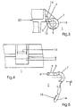
- the handling to be derived from the shaping as well as the functional properties of the hinge-like connecting part 1 can be described as follows: In the open position, the front free end 16 of the tab 8 releases the connection between the cover and the transport container (cf. Fig. 1 ). Since the central part 9 of the connecting part 1 is designed to be flexible, it is possible to guide the connecting part with its front free end 16 to a (not shown) pivot on a transport container and plug into a plug-in opening 5 in the rear portion 4 of the connecting part, in which front free end of the connecting part with its anchoring part 14, as from the FIGS. 3 and 4 visible, barb-like locks. Thus, the connecting part 1 and the pivot pin form a hinge. Is the anchoring part additionally provided with a series of saw teeth 15, as in FIG.
- the ring width of the connecting part 1 can advantageously be adapted to the dimensions of a provided on the object (not shown in the figure) pivot.
- the lid can be used for various transport containers.
- the almost uniform stiffness of the connecting part 1 in the closed state ensures a relation to tensile forces stable connection between the cover and the transport container.
- Preferred material for the hinge-like connection part 1 is plastic.
- the described part can, as initially stated, for example, produce by the known injection molding process. Depending on the choice of die, the part may be integrally attached to the lid or to a sidewall of a shipping container. However, it can also be manufactured as a single part. In a single part design, it is expedient to provide the rear edge 3 of the formed to a tab connecting part 1 with a recess 6, which can be inserted with an attachment piece on a cover or transport container is formed (see Fig. 5 ). The durability of the connector can, if desired, be increased by gluing or welding of the connecting part 1 with a neck receiving it.
Landscapes
- Engineering & Computer Science (AREA)
- Mechanical Engineering (AREA)
- Manufacturing & Machinery (AREA)
- Closures For Containers (AREA)
- Cartons (AREA)
Description
- Die Erfindung betrifft ein scharnierartiges Verbindungsteil zwischen einem Deckel und einem Transportbehälter nach dem Oberbegriff des Patentanspruchs 1.
- Es sind verschiedene Lösungen für scharnierartige Verbindungselemente für schwenkbare Kunststoffteile beziehungsweise als Klemmelemente bekannt. Die Veröffentlichung
GB-A-2 245 309 GB-A-1 241 992 - Zur Erhöhung der mechanischen Festigkeit einer Scharnierverbindung zwischen Auflagedeckel und Transportbehälter werden üblicherweise Scharnierklammern verwendet, die bekanntlich in irgendeiner Form, beispielsweise mit Nieten oder Bolzen, fixiert werden (vgl. Ausführungsbeispiel einer handelsüblichen Scharnierklammer auf Seite 35 Euro-Katalog 1999, Georg Utz AG, Kunststoff-Technik für Lager und Transport). Die Problematik, die sich aus der Verwendung von Scharnierklammern zur Verfestigung von Gelenkverbindung verschließbarer Kunststoffbehälter ergibt, liegt auf der Hand. Neben der relativ aufwendigen Montage wirkt sich verfahrenstechnisch insbesondere die Verwendung verschiedener Materialen nachteilig auf das Recycling des Gebindes aus, da die aus Metall bestehenden Kleinteile des Gebindes vorab zu entfernen sind.
- Aufgabe der vorliegenden Erfindung ist es daher, eine einfache und rezyklierbare Befestigungsvorrichtung für einen Deckel an einen Transportbehälter anzugeben, deren mechanische Stabilität nahezu identisch derjenigen durch eine Scharnierklammer gesicherten Gelenkverbindung ist.
- Diese Aufgabe wird erfindungsgemäß durch die Merkmale des Patentanspruches 1 gelöst. Danach ist vorgesehen, dass ein zwischen einem Deckel und einem Transportbehälter angeordnetes scharnierartiges Verbindungsteil am Deckel oder am Transportbehälter angeordnet und zumindest bereichsweise als flexible Lasche ausgebildet ist, die mit ihrem vorderen freien Ende im geschlossenen Zustand einen vollständigen Ring bildet, welcher dazu bestimmt ist einen Drehzapfen ringförmig zu umschliessen.
- Der Vorteil der Erfindung liegt in der Verwendung eines einzigen Bauteiles, welches gegenüber den herkömmlichen Befestigungsmöglichkeiten von einem Auflagedeckel an einem Transportbehälter die Funktion eines Scharniers unter Ver zicht einer Scharnierklammer übernimmt. Ein weiterer Vorteil der Erfindung liegt in der kostengünstigen Herstellung des Bauteils im Spritzgussverfahren. Darüber hinaus ermöglicht die im Rahmen des Erfindungsgedankens liegende Ausgestaltung des Bauteils mit einer Reihe von Sägezähnen im Bereich des vorderen zu einer Lasche ausgebildeten Endes in vorteilhafter Weise die Ringweite des scharnierartigen Verbindungsteils auf die Maße der zu vernetzenden Objekte abzustimmen.
- Weitere Vorteile der Erfindung folgen aus den abhängigen Patentansprüchen und aus der nachfolgenden Beschreibung, in welcher die Erfindung anhand eines in den schematischen Zeichnungen dargestellten Ausführungsbeispieles näher erläutert wird. Es zeigt:
- Fig. 1
- eine Seitenansicht des scharnierartigen Verbindungsteils im geöffneten Zustand,
- Fig. 2
- eine Frontansicht des Verbindungsteils in Richtung des Pfeils A in Figur 1,
- Fig. 3
- eine Seitenansicht des scharnierartigen Verbindungsteils im geschlossenen Zustand,
- Fig. 4
- eine Frontansicht des Verbindungsteils in Richtung des Pfeils B in Figur 3, und
- Fig. 5
- ein Variante des scharnierartigen Verbindungsteils in Seitenansicht.
- In den Figuren sind für dieselben Elemente jeweils dieselben Bezugszeichen verwendet worden und erstmalige Erklärungen betreffen alle Figuren, wenn nicht ausdrücklich anders erwähnt.
-
Figur 1 zeigt eine Ausführungsform des erfindungsgemäßen scharnierartigen Verbindungsteils 1, bei der das zumindest bereichsweise zu einer flexiblen Lasche 8 ausgebildete Verbindungsteil 1 einstückig an der Stoßkante 22 eines Auflagerandes 21 eines Deckels 20 angebracht ist. Im Rahmen des Erfindungsgedankens ist es jedoch ebenso möglich das Teil im Bereich der Oberkante einer Seitenwand eines (hier nicht dargestellten) Transportbehälters anzuordnen. Für die Funktion des scharnierartigen Verbindungsteils entscheidend ist, dass das Verbindungsteil 1 zumindest bereichsweise flexible Abschnitte aufweist, die einen ringartigen Zusammenschluss ermöglichen. In dem Ausführungsbeispiel nachFigur 1 besitzt das Verbindungsteil 1 einen hinteren geraden Abschnitt 4, welcher mit der Stoßkante 22 eines Deckels 20 einstückig verbunden ist und im Wesentlichen starr ausgebildet ist. In diesen Abschnitt eingelassen ist eine Stecköffnung 5, in die das vordere freie Ende 16 der Lasche 8 im geschlossen Zustand einrastet. Im Anschluss an diesen Abschnitt ist ein bogenförmiger Abschnitt 7 vorgesehen. Vorzugsweise im Mittelteil 9 des Verbindungsteils 1 befindet sich eine wannenartige Vertiefung 10, die so bemessen ist, dass die nach außen weisenden Kanten 12 der seitlichen Begrenzungen 11 bei einem Ringschluss des Verbindungsteils 1 aneinander stoßen und somit dem Verbindungsteil eine ähnliche Stabilität wie einem Vollring geben. In der Praxis kann das Verbindungsteil 1 jedoch auch in Abhängigkeit von der gewünschten Form oder möglichen Zusatzfunktionen mit mehreren Vertiefungen gleichartiger Funktion versehen sein. Im Anschluss an den flexibel gestalteten Mittelteil 9 ist ein weiterer bogenförmiger Abschnitt 13 vorgesehen, welcher zusammen mit den vorgenannten Abschnitten 4, 7 und 9 die Ringform des Verbindungsteils 1 im geschlossenen Zustand (vgl.Figur 3 ) vervollständigt. An diesen bogenförmigen Abschnitt 13 ist ein Verankerungsteil 14 angeformt, welcher hakenförmig und im vorderen Bereich zur Durchdringung der Stecköffnung 5 abgeflacht ausgebildet ist. -
Figur 2 zeigt, dass der zu einer flexiblen Lasche ausgebildete Abschnitt 8 des Verbindungsteils parallel zueinander verlaufende Seitenwände 2 aufweist. Es könnte jedoch auch eine keilförmige Ausprägung der Lasche 8 vorgesehen sein. - Die aus der Formgebung abzuleitende Handhabung ebenso wie die funktionellen Eigenschaften des scharnierartigen Verbindungsteil 1 lassen sich wie folgt beschreiben: In geöffneter Stellung gibt das vordere freie Ende 16 der Lasche 8 die Verbindung zwischen Deckel und Transportbehälter frei (vgl.
Fig. 1 ). Da der Mittelteil 9 des Verbindungsteiles 1 flexibel gestaltet ist, ist es möglich das Verbindungsteil mit seinem vorderen freien Ende 16 um einen (nicht dargestellten) Drehzapfen an einem Transportbehälter zu führen und in eine Stecköffnung 5 im hinteren Abschnitt 4 des Verbindungsteils einzustecken, in die das vordere freie Ende des Verbindungsteil mit seinem Verankerungsteil 14, wie aus denFiguren 3 und 4 ersichtlich, widerhakenähnlich einrastet. Somit bilden das Verbindungsteil 1 und der Drehzapfen ein Scharnier. Ist das Verankerungsteil zusätzlich noch mit einer Reihe von Sägezähnen 15 versehen, wie inFigur 5 schematisch wiedergegeben, kann in vorteilhafter Weise die Ringweite des Verbindungsteils 1 an die Maße eines am Objekt vorgesehenen (in der Figur nicht dargestellten) Drehzapfens angepasst werden. Damit kann der Deckel für verschiedene Transportbehälter verwendet werden. Die nahezu einheitliche Steifheit des Verbindungsteils 1 im geschlossenen Zustand gewährleistet eine gegenüber Zugkräften stabile Verbindung zwischen Deckel und Transportbehälter. - Bevorzugtes Material für das scharnierartige Verbindungsteil 1 ist Kunststoff. Das beschriebene Teil lässt sich, wie anfänglich ausgeführt, beispielsweise mit dem bekannten Spritzgussverfahren herstellen. Abhängig von der Wahl der Matrize kann das Teil einstückig am Deckel oder an einer Seitenwand eines Transportbehälters angebracht sein. Es kann jedoch auch als Einzelteil hergestellt werden. Bei einer Einzelteilausführung ist es zweckmäßig die hintere Stosskante 3 des zu einer Lasche ausgebildeten Verbindungsteils 1 mit einer Einbuchtung 6 zu versehen, welche einsteckbar mit einem Ansatzstutzen an einem Deckel oder Transportbehälter ausgebildet ist (siehe
Fig. 5 ). Die Beständigkeit der Steckverbindung kann falls gewünscht, durch Verkleben oder Verschweissen des Verbindungsteils 1 mit einem ihn aufnehmenden Ansatzstutzen erhöht werden. -
- 1
- Scharnierartiges Verbindungsteil
- 2
- Seitenwand
- 3
- hintere Stoßkante
- 4
- hinterer gerader Abschnitt
- 5
- Stecköffnung
- 6
- Einbuchtung
- 7
- gebogter Abschnitt
- 8
- Lasche
- 9
- Mittelteil
- 10
- Vertiefung
- 11
- Seitliche Begrenzung der Vertiefung
- 12
- Nach außen weisende Kante der seitlichen Begrenzung der Vertiefung
- 13
- gebogter Abschnitt
- 14
- Verankerungsteil
- 15
- Sägezähne
- 16
- Vorderes freies Ende der Lasche
- 17
- 18
- 19
- 20
- Deckel
- 21
- Auflagerand des Deckel
- 22
- Stoßkante des Deckels
Claims (6)
- Scharnierartiges Verbindungsteil (1) zwischen einem Deckel und einem Transportbehälter, das am Deckel oder am Transportbehälter angeordnet und zumindest bereichsweise als flexible Lasche (8) ausgebildet ist, dadurch gekennzeichnet, dass die flexible Lasche (8) mit ihrem vorderen freien Ende (16) im geschlossenen Zustand einen vollständigen Ring bildet, welcher dazu bestimmt ist einen Drehzapfen ringförmig zu umschliessen, und dass auf dem dem freien Ende der Lasche (8) abgewandten Abschnitt (4) des Verbindungselements eine Stecköffnung (5) angeordnet ist, in die das vordere Ende (16) der Lasche (8) einrastbar ist.
- Scharnierartiges Verbindungsteil nach Anspruch 1, dadurch gekennzeichnet, dass das Teil vorzugsweise im Mittelteil (9) eine Vertiefung (10) aufweist, deren seitliche Begrenzungen (11) beim ringförmigen Zusammenschluss zusammenstoßen und damit diesem Bereich eine ähnlich hohe Steifheit verleihen wie die starren Abschnitte des Verbindungsteiles.
- Scharnierartiges Verbindungsteil nach einem der vorherigen Ansprüche, dadurch gekennzeichnet, dass das Verbindungsteil (1) im Bereich seines vorderen zur Lasche ausgebildeten Endes (16) eine Reihe von Sägezähnen (15) aufweist, um die Ringweite einzustellen.
- Scharnierartiges Verbindungsteil nach einem der Ansprüche 1 bis 3, dadurch gekennzeichnet, dass das Verbindungsteil (1) einstückig am Deckel eines Transportbehälters angebracht ist und dazu bestimmt ist mit seinem vorderen zur Lasche ausgebildeten Ende (16) einen Drehzapfen am Transportbehälter zu umschließen.
- Scharnierartiges Verbindungsteil nach einem der Ansprüche 1 bis 3, dadurch gekennzeichnet, dass das Verbindungsteil (1) einstückig am Transportbehälter angebracht ist und dazu bestimmt ist mit seinem vorderen zur Lasche ausgebildeten Ende (17) einen Drehzapfen am Deckel zu umschließen.
- Scharnierartiges Verbindungsteil nach einem der Ansprüche 1 bis 4, dadurch gekennzeichnet, dass die hintere Stosskante (3) des Verbindungsteils (1) mit einer Einbuchtung (6) versehen ist, welche einsteckbar mit einem Ansatzstutzen an einem Deckel oder Transportbehälter ausgebildet ist.
Applications Claiming Priority (2)
| Application Number | Priority Date | Filing Date | Title |
|---|---|---|---|
| CH7652000 | 2000-04-18 | ||
| CH7652000 | 2000-04-18 |
Publications (3)
| Publication Number | Publication Date |
|---|---|
| EP1147993A2 EP1147993A2 (de) | 2001-10-24 |
| EP1147993A3 EP1147993A3 (de) | 2004-01-28 |
| EP1147993B1 true EP1147993B1 (de) | 2008-02-13 |
Family
ID=4534986
Family Applications (1)
| Application Number | Title | Priority Date | Filing Date |
|---|---|---|---|
| EP20010109546 Expired - Lifetime EP1147993B1 (de) | 2000-04-18 | 2001-04-17 | Scharnierartiges Verbindungsteil |
Country Status (3)
| Country | Link |
|---|---|
| EP (1) | EP1147993B1 (de) |
| BR (1) | BR0101502A (de) |
| DE (1) | DE50113573D1 (de) |
Families Citing this family (3)
| Publication number | Priority date | Publication date | Assignee | Title |
|---|---|---|---|---|
| FR2864048B1 (fr) * | 2003-12-22 | 2007-04-06 | Plastic Omnium Cie | Bac de collecte de dechets |
| PL228252B1 (pl) * | 2013-01-14 | 2018-03-30 | Fakro Pp Spolka Z Ograniczona Odpowiedzialnoscia | Schody składane, zwłaszcza lekkie, drewniane |
| GB2516014A (en) * | 2013-07-02 | 2015-01-14 | Colpac Ltd | Container |
Family Cites Families (5)
| Publication number | Priority date | Publication date | Assignee | Title |
|---|---|---|---|---|
| FR1126581A (fr) * | 1955-05-17 | 1956-11-26 | Colson Ets | Collier de serrage |
| GB1241992A (en) * | 1968-02-14 | 1971-08-11 | Itw Ltd | Hinges |
| GB1436703A (en) * | 1973-03-28 | 1976-05-26 | Fletcher F | Releasable joint |
| GB2245309B (en) * | 1990-06-19 | 1994-02-16 | Lin Pac Mouldings | A hinge assembly |
| DE9306248U1 (de) * | 1993-01-05 | 1993-07-08 | Kodak Ag, 7000 Stuttgart | Scharnier |
-
2001
- 2001-04-17 DE DE50113573T patent/DE50113573D1/de not_active Expired - Lifetime
- 2001-04-17 EP EP20010109546 patent/EP1147993B1/de not_active Expired - Lifetime
- 2001-04-18 BR BR0101502A patent/BR0101502A/pt not_active Application Discontinuation
Also Published As
| Publication number | Publication date |
|---|---|
| PL347051A1 (en) | 2001-10-22 |
| EP1147993A3 (de) | 2004-01-28 |
| DE50113573D1 (de) | 2008-03-27 |
| BR0101502A (pt) | 2001-11-13 |
| EP1147993A2 (de) | 2001-10-24 |
Similar Documents
| Publication | Publication Date | Title |
|---|---|---|
| DE2711337A1 (de) | Kunststoffklammer | |
| DE3221649A1 (de) | Wischblattbuegel mit seitlichem verbindungsglied | |
| EP1101889B1 (de) | Kraftfahrzeug-Türschloss | |
| DE6605929U (de) | Selbstsicherndes befestigungselement | |
| DE10144166A1 (de) | Schloss für eine Kraftfahrzeugtür | |
| DE10155735A1 (de) | Halter für einen Körper und Befestigungsanordnung | |
| EP1431641B1 (de) | Rohrschelle | |
| DE10044826A1 (de) | Trimmteil für eine Hecktür eines Kraftfahrzeuges | |
| EP1348585B1 (de) | Verfahrbarer Deckel für Fahrzeugdach sowie Schiebehebedach-Modul | |
| DE60004604T2 (de) | Befestigungsclip zur Verbindung von Gegenständen auf einer Platte und Modul mit Befestigungsclip | |
| EP1036728B1 (de) | Längsgesickter Träger, insbesondere Dachträger für ein Kraftfahrzeug | |
| DE3222810A1 (de) | Haltegriff od. dgl. fuer fahrzeuge | |
| EP1147993A2 (de) | Scharnierartiges Verbindungsteil | |
| DE4122540A1 (de) | Bremseinrichtung fuer einen klappbaren deckel | |
| EP1241082B1 (de) | Kraftfahrzeug mit wenigstens einer klappbaren Haube, insbesondere Motorraum- und/oder Gepäckraumdeckel | |
| EP1134129B1 (de) | Haltevorrichtung für den Überrollkörper eines Überrollschutzsystems | |
| DE9407234U1 (de) | Kulisse für ein verschiebbares und/oder aufstellbares Dachteil eines Kraftfahrzeuges | |
| WO2018206762A1 (de) | Drehgelenkanordnung mit einem mittels spritzguss gefertigten gelenkbolzen | |
| DE102005042288A1 (de) | Abdeckung für die Ladekante eines Kraftfahrzeuges und Kraftfahrzeug mit einer solchen Abdeckung | |
| DE29921802U1 (de) | Scharnierfeder für eine Tankklappe eines Kraftfahrzeugs | |
| EP1365092B1 (de) | Schiebeverschluss für eine schwenkbare Abdeckklappe | |
| DE19527431A1 (de) | Gegenlagerböckchen für eine Fahrzeugsonnenblende | |
| DE10043226B4 (de) | Struktur für das Anbringen eines Verbinders für ein einer Öffnung eines Fahrzeugkörpers zugeordnetes Öffnungs-Schließ-Element | |
| DE10235213B4 (de) | Heckträger für ein Kraftfahrzeug | |
| DE102004062467B4 (de) | Müllsammelbehälter |
Legal Events
| Date | Code | Title | Description |
|---|---|---|---|
| PUAI | Public reference made under article 153(3) epc to a published international application that has entered the european phase |
Free format text: ORIGINAL CODE: 0009012 |
|
| AK | Designated contracting states |
Kind code of ref document: A2 Designated state(s): AT BE CH CY DE DK ES FI FR GB GR IE IT LI LU MC NL PT SE TR |
|
| AX | Request for extension of the european patent |
Free format text: AL;LT;LV;MK;RO;SI |
|
| RIN1 | Information on inventor provided before grant (corrected) |
Inventor name: OPPENLAENDER, WILFRIED Inventor name: DUBOIS, JEAN-MARC |
|
| PUAL | Search report despatched |
Free format text: ORIGINAL CODE: 0009013 |
|
| AK | Designated contracting states |
Kind code of ref document: A3 Designated state(s): AT BE CH CY DE DK ES FI FR GB GR IE IT LI LU MC NL PT SE TR |
|
| AX | Request for extension of the european patent |
Extension state: AL LT LV MK RO SI |
|
| RIC1 | Information provided on ipc code assigned before grant |
Ipc: 7E 05D 5/14 B Ipc: 7E 05D 9/00 B Ipc: 7B 65D 43/16 A |
|
| 17P | Request for examination filed |
Effective date: 20040413 |
|
| AKX | Designation fees paid |
Designated state(s): CH DE FR GB LI |
|
| 17Q | First examination report despatched |
Effective date: 20050203 |
|
| GRAP | Despatch of communication of intention to grant a patent |
Free format text: ORIGINAL CODE: EPIDOSNIGR1 |
|
| GRAS | Grant fee paid |
Free format text: ORIGINAL CODE: EPIDOSNIGR3 |
|
| GRAA | (expected) grant |
Free format text: ORIGINAL CODE: 0009210 |
|
| AK | Designated contracting states |
Kind code of ref document: B1 Designated state(s): CH DE FR GB LI |
|
| REG | Reference to a national code |
Ref country code: GB Ref legal event code: FG4D Free format text: NOT ENGLISH |
|
| REG | Reference to a national code |
Ref country code: CH Ref legal event code: EP |
|
| REF | Corresponds to: |
Ref document number: 50113573 Country of ref document: DE Date of ref document: 20080327 Kind code of ref document: P |
|
| REG | Reference to a national code |
Ref country code: CH Ref legal event code: NV Representative=s name: SPIERENBURG & PARTNER AG, PATENT- UND MARKENANWAEL |
|
| ET | Fr: translation filed | ||
| PLBE | No opposition filed within time limit |
Free format text: ORIGINAL CODE: 0009261 |
|
| STAA | Information on the status of an ep patent application or granted ep patent |
Free format text: STATUS: NO OPPOSITION FILED WITHIN TIME LIMIT |
|
| 26N | No opposition filed |
Effective date: 20081114 |
|
| REG | Reference to a national code |
Ref country code: FR Ref legal event code: ST Effective date: 20081231 |
|
| REG | Reference to a national code |
Ref country code: FR Ref legal event code: RN |
|
| REG | Reference to a national code |
Ref country code: FR Ref legal event code: FC |
|
| PG25 | Lapsed in a contracting state [announced via postgrant information from national office to epo] |
Ref country code: FR Free format text: LAPSE BECAUSE OF NON-PAYMENT OF DUE FEES Effective date: 20080430 |
|
| PGRI | Patent reinstated in contracting state [announced from national office to epo] |
Ref country code: FR Effective date: 20090304 |
|
| REG | Reference to a national code |
Ref country code: FR Ref legal event code: PLFP Year of fee payment: 16 |
|
| PGFP | Annual fee paid to national office [announced via postgrant information from national office to epo] |
Ref country code: CH Payment date: 20160308 Year of fee payment: 16 |
|
| PGFP | Annual fee paid to national office [announced via postgrant information from national office to epo] |
Ref country code: DE Payment date: 20160426 Year of fee payment: 16 Ref country code: GB Payment date: 20160425 Year of fee payment: 16 |
|
| PGFP | Annual fee paid to national office [announced via postgrant information from national office to epo] |
Ref country code: FR Payment date: 20160423 Year of fee payment: 16 |
|
| REG | Reference to a national code |
Ref country code: DE Ref legal event code: R119 Ref document number: 50113573 Country of ref document: DE |
|
| REG | Reference to a national code |
Ref country code: CH Ref legal event code: PL |
|
| GBPC | Gb: european patent ceased through non-payment of renewal fee |
Effective date: 20170417 |
|
| REG | Reference to a national code |
Ref country code: FR Ref legal event code: ST Effective date: 20171229 |
|
| PG25 | Lapsed in a contracting state [announced via postgrant information from national office to epo] |
Ref country code: FR Free format text: LAPSE BECAUSE OF NON-PAYMENT OF DUE FEES Effective date: 20170502 Ref country code: DE Free format text: LAPSE BECAUSE OF NON-PAYMENT OF DUE FEES Effective date: 20171103 |
|
| PG25 | Lapsed in a contracting state [announced via postgrant information from national office to epo] |
Ref country code: LI Free format text: LAPSE BECAUSE OF NON-PAYMENT OF DUE FEES Effective date: 20170430 Ref country code: CH Free format text: LAPSE BECAUSE OF NON-PAYMENT OF DUE FEES Effective date: 20170430 Ref country code: GB Free format text: LAPSE BECAUSE OF NON-PAYMENT OF DUE FEES Effective date: 20170417 |