EP1146602A2 - Steckverbinder - Google Patents
Steckverbinder Download PDFInfo
- Publication number
- EP1146602A2 EP1146602A2 EP01108322A EP01108322A EP1146602A2 EP 1146602 A2 EP1146602 A2 EP 1146602A2 EP 01108322 A EP01108322 A EP 01108322A EP 01108322 A EP01108322 A EP 01108322A EP 1146602 A2 EP1146602 A2 EP 1146602A2
- Authority
- EP
- European Patent Office
- Prior art keywords
- connector
- locking
- locking module
- parts
- connector according
- Prior art date
- Legal status (The legal status is an assumption and is not a legal conclusion. Google has not performed a legal analysis and makes no representation as to the accuracy of the status listed.)
- Withdrawn
Links
- 238000006073 displacement reaction Methods 0.000 claims description 4
- 238000003780 insertion Methods 0.000 claims description 4
- 230000037431 insertion Effects 0.000 claims description 4
- 230000006835 compression Effects 0.000 description 5
- 238000007906 compression Methods 0.000 description 5
- 238000009434 installation Methods 0.000 description 1
- 230000007257 malfunction Effects 0.000 description 1
- 238000000034 method Methods 0.000 description 1
- 230000001960 triggered effect Effects 0.000 description 1
Images


Classifications
-
- H—ELECTRICITY
- H01—ELECTRIC ELEMENTS
- H01R—ELECTRICALLY-CONDUCTIVE CONNECTIONS; STRUCTURAL ASSOCIATIONS OF A PLURALITY OF MUTUALLY-INSULATED ELECTRICAL CONNECTING ELEMENTS; COUPLING DEVICES; CURRENT COLLECTORS
- H01R13/00—Details of coupling devices of the kinds covered by groups H01R12/70 or H01R24/00 - H01R33/00
- H01R13/64—Means for preventing incorrect coupling
- H01R13/641—Means for preventing incorrect coupling by indicating incorrect coupling; by indicating correct or full engagement
-
- H—ELECTRICITY
- H01—ELECTRIC ELEMENTS
- H01R—ELECTRICALLY-CONDUCTIVE CONNECTIONS; STRUCTURAL ASSOCIATIONS OF A PLURALITY OF MUTUALLY-INSULATED ELECTRICAL CONNECTING ELEMENTS; COUPLING DEVICES; CURRENT COLLECTORS
- H01R13/00—Details of coupling devices of the kinds covered by groups H01R12/70 or H01R24/00 - H01R33/00
- H01R13/62—Means for facilitating engagement or disengagement of coupling parts or for holding them in engagement
- H01R13/629—Additional means for facilitating engagement or disengagement of coupling parts, e.g. aligning or guiding means, levers, gas pressure electrical locking indicators, manufacturing tolerances
- H01R13/633—Additional means for facilitating engagement or disengagement of coupling parts, e.g. aligning or guiding means, levers, gas pressure electrical locking indicators, manufacturing tolerances for disengagement only
- H01R13/635—Additional means for facilitating engagement or disengagement of coupling parts, e.g. aligning or guiding means, levers, gas pressure electrical locking indicators, manufacturing tolerances for disengagement only by mechanical pressure, e.g. spring force
Definitions
- the invention relates to a connector with two pluggable, interlocking connector parts. It can be particularly are an electrical connector.
- the two connector parts must be correct be coupled together. For this it is particularly necessary that these two connector parts are actually completely plugged together are. In most cases it is not easy possible to determine the condition of the connector located.
- the aim of the invention is to provide a connector of the type mentioned to create the most optimal possible with a simple structure Allowing control of its respective state is permitted as well is easy to use.
- a locking module on a first of the two connector parts generally in plug-in or guided axially and by spring force in a Plug direction is loaded in the front locking position, in which it is plugged together Connector parts with one on the other connector part provided counter-element cooperates, the locking module when plugging the two connector parts together, first counter the spring force moved out of the locked position and only at at least essentially completely assembled connector parts is released again by the spring force back into its Locking position to be pushed and with the counter element latch.
- This training ensures that the locking of the two connector parts, which are in particular a housing lock can act, is only effective if a full contact is guaranteed.
- the required security is also in particular blind operations performed.
- the connector is always either active or ready to be plugged in. Regarding locking results in a kind of good-bad function, through which a high Reliability is achieved. If the two connector parts are not correct put together, so they are automatically by the spring force separated again. Only when the connector parts are correctly connected the locking module is released to then to be shifted to its locking position by the same spring force and to lock with the counter element.
- the locking module is advantageously with a locking element provided, which is resiliently biased into a locked position in which it Put the two connector parts together on the other connector part Attachment comes to a relative displacement between the locking module and to prevent the other connector part until the two Connector parts at least essentially completely plugged together are, whereupon the locking element via an associated with the first connector part Trigger element is moved out of its locked position to release the spring-loaded locking module.
- the trigger element can comprise a control surface on which the Put the two connector parts together with the locking element connected sliding element slides and through which the sliding element is shifted accordingly to the locking element from its locked position to move out.
- the trigger element generally transverse to the direction of insertion between its locked position and a release position.
- the trigger element is preferred pivotable relative to the first connector part.
- control surface has one Inclined direction on the course.
- the spring force loading the locking module into the locking position is advantageously by at least one between the locking module and the spring arranged on the first connector part, e.g. Compression spring, generated.
- the locking module on the first connector part is preassembled and in its preassembly position against falling off secured by the connector part and by the spring force in its locking position is held.
- the locking position is advantageous by at least one provided on the locking module Defines resilient stop, which is provided in a on the first connector part The guide engages and is loaded by the spring force into a locking position is in the locking module assuming its locking position abuts an end face of the guide.
- the resilient stop expediently provided with a ramp surface, via an opening provided on the locking module a corresponding tool or the like is accessible to the To move the stop against the spring force out of its locking position and thus the locking module again from the first connector part to solve.
- Connector at least two resilient stops are provided, arranged on opposite sides of the locking module are and in the assembled state of the locking module each engage in a guide provided on the first connector part.
- the locking module is expediently with a latching opening provided with which the counter element when plugging the two together Connector parts locked as soon as the locking module due to the spring force returns to its locked position. It is from Advantage if the locking module has a locking opening Latch arm and the counter element comprises a projection, which at least essentially fully assembled connector parts in engages the locking opening.
- a resilient locking arm and the projection are advantageously provided provided with a ramp surface so that the locking arm when plugging together of the two connector parts first through the ramp surface of the lead is pushed out before it goes back into his The locking position snaps back and locks with the projection.
- the locking arm can be part of a two-armed lever, the other of which Arm is preferably provided with a corrugation. So that is special even with a blindly carried out plugging process a simple and corresponding reliable control of the respective connector status possible.
- the connector is the one with the locking module first connector part as a plug-in part and the other connector part as a receiving part executed.
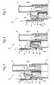
- FIGS. 1 to 5 each have a plug connector 10 with two pluggable, interlocking connector parts 12, 14 shown. In particular, this can be an electrical connector act.
- a locking module 16 On a first 12 of the two connector parts 12, 14, here a plug-in part, is a locking module 16 generally in the plug or axial direction S slidably guided and by spring force, for example by two between the locking module 16 and the first connector part 12 arranged compression springs 18 can be generated in a Insertion direction S front locking position (see Figures 1 and 3) loaded, in which it is with assembled connector parts 12, 14 with a on the other connector part 14, here a receiving part with a socket housing, provided counter element 20 cooperates.
- the locking module 16 When plugging together of the two connector parts 12, 14 becomes the locking module 16 initially against the spring force from the locking position moved out (see e.g. Figures 3 and 4). Only at least essentially fully assembled connector parts 12, 14 will the locking module 16 released again by the spring force 18 to be pushed back into its locking position and with the To lock the counter element 20.
- the locking module 16 can each be provided with a locking element 22 be resiliently biased into a locked position in which it when plugging together the two connector parts 12, 14 on the other Connector part 14 comes to rest (cf. in particular Figures 1 and 3) by a relative displacement between the locking module 16 and to prevent the other connector part 14 until the two connector parts 12, 14 at least essentially completely plugged together are. Only when this last-mentioned connector state is reached is, i.e. the two connector parts 12, 14 at least essentially are completely plugged together, the respective locking element 22nd for example via a trigger element assigned to the first connector part 12 24 moved out of its locked position, for example Locking module loaded by compression springs 18 into its locking position 16 to release.
- the trigger element 24 can generally transversely to the direction S be relocatable between its locked position and a release position.
- the locking module 16 is each provided with a latch opening 26, with which the counter element 20 when plugging the two connector parts together 12, 14 locked as soon as the locking module 16 due to Spring force, i.e. for example, because of the two between the locking module 16 and the first connector part 12 arranged springs 18, resumes its locking position.
- the locking module 16 can each have a latching opening 26 have locking arm 28 and the counter element by a Projection 20 may be formed, which is at least substantially complete assembled connector parts 12, 14 engages in the locking opening 26 (see in particular Figure 5).
- a resilient locking arm 28 and the projection are expediently provided 20 provided with a ramp surface 30 so that the resilient Latching arm 28 when the two connector parts 12, 14 are plugged together first pushed outwards by the ramp surface 30 of the projection 20 before it snaps back into its locked position and locked with the projection 20.
- the locking arm 28 can be part of a two-armed lever 32, the other Arm 34 is preferably provided with a groove 36.
- the locking module 16 can be preassembled on the first connector part 12 and in its preassembly position against falling off the connector part be secured.
- the locking module is in this pre-assembly position 16 then by the spring force 18 in its locking position held.
- the locking position for example by two on top of each other Resilient stops 38 provided on the sides of the locking module 16 be defined, each in a provided on the first connector part 12 Intervene guide 40 and loaded resiliently into an outer locking position are in the locking module occupying its lower locking position 16 bear against an end face 42 of the respective guide 40.
- the resilient stops 38 can each have a ramp surface 44, which is provided via a respective one on the locking module 16 Opening 46 by means of an appropriate tool or the like is accessible to the respective stop 38 against it moving spring force out of its locking position and thus the locking module 16 again from the first connector part 12 to solve.
- the triggering element can 24 comprise a control surface 48, on which the two connector parts 12, 14 connected to the locking element 22 Sliding element 50 slides along and through which the sliding element 50 correspondingly is shifted to the locking element 22 from its locked position to move out.
- the control surface 48 can be in the direction of insertion S have an inclined course.
- the two connector elements 12, 14 already completely plugged together, which in the present case means that the receptacle housing is fully inserted into the receptacle is. Accordingly, the locking element 22 from its locked position moved out, whereby the locking module 16 is released. In however, the locking module 16 takes this representation according to FIG still in its retracted top position.
- FIG. 5 shows the plug connector 10 in question when the connectors are fully connected Connector parts 12, 14 and its locking position engaging locking module 16. The locking arm 28 is thus with the Projection 20 locked.
- the respective springs here, for example, the two compression springs 18, tensioned.
- the locking module 16 is then automatically in its locking position transferred.
- the respective are in this locking position Springs then relaxed.
Landscapes
- Details Of Connecting Devices For Male And Female Coupling (AREA)
Abstract
Description
- Figur 1
- eine schematische, perspektivische Darstellung eines zwei zusammensteckbare, miteinander verriegelbare Verbinderteile umfassenden Steckverbinders,
- Figur 2
- eine schematische, auseinandergezogene Darstellung des Steckverbinders gemäß Figur 1,
- Figur 3
- eine schematische, teilweise geschnittene Darstellung einer weiteren Ausführungsform eines Steckverbinders, bei der die beiden Verbinderteile gerade so weit zusammengesteckt sind, daß das dem Verriegelungsmodul zugeordnete Sperrelement am anderen Verbinderteil zur Anlage kommt,
- Figur 4
- eine schematische, teilweise geschnittene Darstellung des Steckverbinders gemäß Figur 3, bei der die beiden Verbinderteile bereits vollständig zusammengesteckt sind und das Sperrelement entsprechend aus seiner Sperrstellung herausbewegt ist, d.h. das Verriegelungsmodul freigegeben ist, wobei das Verriegelungsmodul jedoch noch seine zurückgezogene Position einnimmt, und
- Figur 5
- eine schematische, teilweise geschnittene Darstellung des Steckverbinders gemäß Figur 3 bei vollständig zusammengesteckten Verbinderteilen und seine Verriegelungsposition einnehmendem Verriegelungsmodul.
- 10
- Steckverbinder
- 12
- Verbinderteil
- 14
- Verbinderteil
- 16
- Verriegelungsmodul
- 18
- Federkraft, Druckfedern
- 20
- Gegenelement, Vorsprung
- 22
- Sperrelement
- 24
- Auslöseelement
- 26
- Rastöffnung
- 28
- Rastarm
- 30
- Auflauffläche
- 32
- zweiarmiger Hebel
- 34
- Hebelarm
- 36
- Riffelung
- 38
- federnder Anschlag
- 40
- Führung
- 42
- Endfläche
- 44
- Auflauffäche
- 46
- Öffnung
- 48
- Steuerfläche
- 50
- Gleitelement
- S
- Steck- oder Axialrichtung
Claims (16)
- Steckverbinder (10) mit zwei zusammensteckbaren, miteinander verriegelbaren Verbinderteilen (12, 14),
dadurch gekennzeichnet, daß ein Verriegelungsmodul (16) an einem ersten (12) der beiden Verbinderteile (12, 14) allgemein in Steck- oder Axialrichtung (S) verschiebbar geführt und durch Federkraft (18) in eine in Steckrichtung (S) vordere Verriegelungsposition belastet ist, in der es bei zusammengesteckten Verbinderteilen (12, 14) mit einem am anderen Verbinderteil (14) vorgesehenen Gegenelement (20) zusammenwirkt, wobei das Verriegelungsmodul (16) beim Zusammenstecken der beiden Verbinderteile (12, 14) zunächst entgegen der Federkraft (18) aus der Verriegelungsposition herausbewegt und erst bei zumindest im wesentlichen vollständig zusammengesteckten Verbinderteilen (12, 14) wieder freigegeben wird, um durch die Federkraft (18) wieder in seine Verriegelungsposition gedrängt zu werden und mit dem Gegenelement (20) zu verrasten. - Steckverbinder nach Anspruch 1,
dadurch gekennzeichnet, daß das Verriegelungsmodul (16) mit einem Sperrelement (22) versehen ist, das federnd in eine Sperrstellung vorbelastet ist, in der es beim Zusammenstecken der beiden Verbinderteile (12, 14) am anderen Verbinderteil (14) zur Anlage kommt, um eine Relativverschiebung zwischen dem Verriegelungsmodul (16) und dem anderen Verbinderteil (14) zu verhindern, bis die beiden Verbinderteile (12, 14) zumindest im wesentlichen vollständig zusammengesteckt sind, woraufhin das Sperrelement (22) über ein dem ersten Verbinderteil (12) zugeordnetes Auslöseelement (24) aus seiner Sperrstellung herausbewegt wird, um das federbelastete Verriegelungsmodul (16) freizugeben. - Steckverbinder nach Anspruch 2,
dadurch gekennzeichnet, daß das Auslöseelement (24) eine Steuerfläche (48) umfaßt, an der beim Zusammenstecken der beiden Verbinderteile (12, 14) ein mit dem Sperrelement (22) verbundenes Gleitelement (50) entlanggleitet und durch die das Gleitelement (50) entsprechend verlagert wird, um das Sperrelement (22) aus seiner Sperrstellung herauszubewegen. - Steckverbinder nach Anspruch 2 oder 3,
dadurch gekennzeichnet, daß das Auslöseelement (24) allgemein quer zur Steckrichtung (S) zwischen seiner Sperrstellung und einer Freigabestellung verlagerbar ist. - Steckverbinder nach Anspruch 4,
dadurch gekennzeichnet, daß das Auslöseelement (24) relativ zum ersten Verbinderteil (12) schwenkbar ist. - Steckverbinder nach einem der vorhergehenden Ansprüche,
dadurch gekennzeichnet, daß die Steuerfläche (48) einen zur Steckrichtung (S) geneigten Verlauf aufweist. - Steckverbinder nach einem der vorhergehenden Ansprüche,
dadurch gekennzeichnet, daß die das Verriegelungsmodul (16) in die Verriegelungsposition belastende Federkraft durch wenigstens eine zwischen dem Verriegelungsmodul (16) und dem ersten Verbinderteil (12) angeordnete Feder (18) erzeugt ist. - Steckverbinder nach einem der vorhergehenden Ansprüche,
dadurch gekennzeichnet, daß das Verriegelungsmodul (16) an dem ersten Verbinderteil (12) vormontierbar ist und in seiner Vormontagestellung gegen ein Abfallen vom Verbinderteil (12) gesichert und durch die Federkraft (18) in seiner Verriegelungsposition gehalten ist. - Steckverbinder nach Anspruch 8,
dadurch gekennzeichnet, daß die Verriegelungsposition durch wenigstens einen am Verriegelungsmodul (16) vorgesehenen federnden Anschlag (38) definiert ist, der in eine am ersten Verbinderteil (12) vorgesehene Führung (40) eingreift und federnd in eine Raststellung belastet ist, in der er bei seine Verriegelungsposition einnehmendem Verriegelungsmodul (16) an einer Endfläche (42) der Führung (40) anliegt. - Steckverbinder nach Anspruch 9,
dadurch gekennzeichnet, daß der federnde Anschlag (38) mit einer Auflauffläche (44) versehen ist, die über eine am Verriegelungsmodul (16) vorgesehene Öffnung (46) mittels eines entsprechenden Werkzeugs oder dergleichen zugänglich ist, um den Anschlag (38) entgegen der Federkraft aus seiner Raststellung herauszubewegen und damit das Verriegelungsmodul (16) wieder von dem ersten Verbinderteil (12) zu lösen. - Steckverbinder nach Anspruch 10,
dadurch gekennzeichnet, daß wenigstens zwei federnde Anschläge (38) vorgesehen sind, die auf einander gegenüberliegenden Seiten des Verriegelungsmoduls (16) angeordnet sind und im montierten Zustand des Verriegelungsmoduls jeweils in eine am ersten Verbinderteil (12) vorgesehene Führung (40) eingreifen. - Steckverbinder nach einem der vorhergehenden Ansprüche,
dadurch gekennzeichnet, daß das Verriegelungsmodul (16) mit einer Rastöffnung (26) versehen ist, mit der das Gegenelement (20) beim Zusammenstecken der beiden Verbinderteile (12, 14) verrastet, sobald das Verriegelungsmodul (16) aufgrund der Federkraft (18) wieder seine Verriegelungsposition einnimmt. - Steckverbinder nach Anspruch 12,
dadurch gekennzeichnet, daß das Verriegelungsmodul (16) einen die Rastöffnung (26) aufweisenden Rastarm (28) und das Gegenelement einen Vorsprung (20) umfaßt, der bei zumindest im wesentlichen vollständig zusammengesteckten Verbinderteilen (12, 14) in die Rastöffnung (26) eingreift. - Steckverbinder nach Anspruch 13,
dadurch gekennzeichnet, daß ein federnder Rastarm (28) vorgesehen und der Vorsprung (20) mit einer Auflauffläche (30) versehenen ist, so daß der Rastarm (28) beim Zusammenstecken der beiden Verbinderteile (12, 14) zunächst durch die Auflauffläche (30) des Vorsprungs (20) nach außen gedrängt wird, bevor er wieder in seine Verriegelungsposition zurückschnappt und mit dem Vorsprung (20) verrastet. - Steckverbinder nach einem der vorhergehenden Ansprüche,
dadurch gekennzeichnet, daß der Rastarm (28) Teil eines zweiarmigen Hebels (32) ist, dessen anderer Arm (34) vorzugsweise mit einer Riffelung (36) versehen ist. - Steckverbinder nach einem der vorhergehenden Ansprüche,
dadurch gekennzeichnet, daß das mit dem Verriegelungsmodul (16) versehene erste Verbinderteil (12) als Steckteil und das andere Verbinderteil (14) als Aufnahmeteil ausgeführt ist.
Applications Claiming Priority (2)
| Application Number | Priority Date | Filing Date | Title |
|---|---|---|---|
| DE2000118017 DE10018017A1 (de) | 2000-04-11 | 2000-04-11 | Steckverbinder |
| DE10018017 | 2000-04-11 |
Publications (2)
| Publication Number | Publication Date |
|---|---|
| EP1146602A2 true EP1146602A2 (de) | 2001-10-17 |
| EP1146602A3 EP1146602A3 (de) | 2004-11-10 |
Family
ID=7638393
Family Applications (1)
| Application Number | Title | Priority Date | Filing Date |
|---|---|---|---|
| EP01108322A Withdrawn EP1146602A3 (de) | 2000-04-11 | 2001-04-02 | Steckverbinder |
Country Status (2)
| Country | Link |
|---|---|
| EP (1) | EP1146602A3 (de) |
| DE (1) | DE10018017A1 (de) |
Citations (1)
| Publication number | Priority date | Publication date | Assignee | Title |
|---|---|---|---|---|
| EP0981185A2 (de) * | 1998-08-20 | 2000-02-23 | Sumitomo Wiring Systems, Ltd. | Verbinder mit Kupplungserkennungsmitteln |
Family Cites Families (3)
| Publication number | Priority date | Publication date | Assignee | Title |
|---|---|---|---|---|
| JP3285307B2 (ja) * | 1996-03-07 | 2002-05-27 | 矢崎総業株式会社 | 半嵌合防止コネクタ |
| JP3086849B2 (ja) * | 1996-08-06 | 2000-09-11 | 矢崎総業株式会社 | コネクタ嵌合構造 |
| US5993238A (en) * | 1996-12-19 | 1999-11-30 | Yazaki Corporation | Half-fitting prevention connector |
-
2000
- 2000-04-11 DE DE2000118017 patent/DE10018017A1/de not_active Withdrawn
-
2001
- 2001-04-02 EP EP01108322A patent/EP1146602A3/de not_active Withdrawn
Patent Citations (1)
| Publication number | Priority date | Publication date | Assignee | Title |
|---|---|---|---|---|
| EP0981185A2 (de) * | 1998-08-20 | 2000-02-23 | Sumitomo Wiring Systems, Ltd. | Verbinder mit Kupplungserkennungsmitteln |
Also Published As
| Publication number | Publication date |
|---|---|
| DE10018017A1 (de) | 2001-10-25 |
| EP1146602A3 (de) | 2004-11-10 |
Similar Documents
| Publication | Publication Date | Title |
|---|---|---|
| DE69415164T2 (de) | Elektrischer Verbinder mit Lagesicherungssystem. | |
| DE19940489B4 (de) | Steckverbindung | |
| DE10221862B4 (de) | Steckverbindung zur Verhinderung eines unvollständig verbundenen Zustands | |
| DE69734745T2 (de) | Verbinder | |
| DE69402647T2 (de) | Verbesserungen an Gehäusen von elektrischen Verbindern | |
| EP0847604B1 (de) | Elektrischer verbinder mit kontaktsicherungsschieber | |
| WO2007016794A1 (de) | Sicherungsvorrichtung für einen stecker (patch guard) | |
| EP1449280A1 (de) | Steckverbinder mit w hrend des steckvorgangs verrastender se kund rverriegelung | |
| DE9411509U1 (de) | Steckverbindergehäuse | |
| DE102020207916A1 (de) | Steckverbinderanordnung für einen elektrischen anschluss mit einer anschlusssperre | |
| EP0984524B1 (de) | Zweiteiliger elektrischer Steckverbinder mit einem Koppelteil und einem bewegbaren Kontrollelement | |
| EP1865808A1 (de) | Teleskopführung für ein in einem möbelkorpus verschiebbar angeordnetes möbelteil | |
| DE3015138C2 (de) | Verrast- u. verriegelbarer Steckverbinder | |
| DE69622082T2 (de) | Verbindungsmodul mit abnehmbaren Kontakten und Anwendung in Verbindungsleisten | |
| EP0923167A1 (de) | Steckverbindung mit automatischem Auswurf | |
| DE10313667B3 (de) | Stecker mit Schieber zum Verbinden mit einer Steckbuchse | |
| DE10018017A1 (de) | Steckverbinder | |
| DE3911696C2 (de) | ||
| EP1526616A1 (de) | Elektrischer Steckverbinder | |
| DE19604249C2 (de) | Steckverbindung mit Einrichtung zum Erfassen des Steckzustands | |
| DE3922882A1 (de) | Verriegelbarer steckverbinder | |
| EP1841017B1 (de) | Steckverbinder | |
| DE29719417U1 (de) | Fallenschloß mit umstellbarer Schloßfalle | |
| DE4139723A1 (de) | Steckdosenoberteil mit mechanischer verriegelung | |
| EP1032086B1 (de) | Steckverbinder |
Legal Events
| Date | Code | Title | Description |
|---|---|---|---|
| PUAI | Public reference made under article 153(3) epc to a published international application that has entered the european phase |
Free format text: ORIGINAL CODE: 0009012 |
|
| AK | Designated contracting states |
Kind code of ref document: A2 Designated state(s): AT BE CH CY DE DK ES FI FR GB GR IE IT LI LU MC NL PT SE TR |
|
| AX | Request for extension of the european patent |
Free format text: AL;LT;LV;MK;RO;SI |
|
| PUAL | Search report despatched |
Free format text: ORIGINAL CODE: 0009013 |
|
| AK | Designated contracting states |
Kind code of ref document: A3 Designated state(s): AT BE CH CY DE DK ES FI FR GB GR IE IT LI LU MC NL PT SE TR |
|
| AX | Request for extension of the european patent |
Extension state: AL LT LV MK RO SI |
|
| RIC1 | Information provided on ipc code assigned before grant |
Ipc: 7H 01R 13/627 B Ipc: 7H 01R 13/629 A |
|
| 17P | Request for examination filed |
Effective date: 20050504 |
|
| AKX | Designation fees paid |
Designated state(s): AT BE CH CY DE DK ES FI FR GB GR IE IT LI LU MC NL PT SE TR |
|
| 17Q | First examination report despatched |
Effective date: 20050802 |
|
| GRAP | Despatch of communication of intention to grant a patent |
Free format text: ORIGINAL CODE: EPIDOSNIGR1 |
|
| STAA | Information on the status of an ep patent application or granted ep patent |
Free format text: STATUS: THE APPLICATION IS DEEMED TO BE WITHDRAWN |
|
| 18D | Application deemed to be withdrawn |
Effective date: 20080708 |