EP1146024A1 - Process for producing dielectric ceramic composition - Google Patents
Process for producing dielectric ceramic composition Download PDFInfo
- Publication number
- EP1146024A1 EP1146024A1 EP00964643A EP00964643A EP1146024A1 EP 1146024 A1 EP1146024 A1 EP 1146024A1 EP 00964643 A EP00964643 A EP 00964643A EP 00964643 A EP00964643 A EP 00964643A EP 1146024 A1 EP1146024 A1 EP 1146024A1
- Authority
- EP
- European Patent Office
- Prior art keywords
- subcomponent
- moles
- powder
- calcination
- dielectric ceramic
- Prior art date
- Legal status (The legal status is an assumption and is not a legal conclusion. Google has not performed a legal analysis and makes no representation as to the accuracy of the status listed.)
- Granted
Links
Images








Classifications
-
- C—CHEMISTRY; METALLURGY
- C04—CEMENTS; CONCRETE; ARTIFICIAL STONE; CERAMICS; REFRACTORIES
- C04B—LIME, MAGNESIA; SLAG; CEMENTS; COMPOSITIONS THEREOF, e.g. MORTARS, CONCRETE OR LIKE BUILDING MATERIALS; ARTIFICIAL STONE; CERAMICS; REFRACTORIES; TREATMENT OF NATURAL STONE
- C04B35/00—Shaped ceramic products characterised by their composition; Ceramics compositions; Processing powders of inorganic compounds preparatory to the manufacturing of ceramic products
- C04B35/01—Shaped ceramic products characterised by their composition; Ceramics compositions; Processing powders of inorganic compounds preparatory to the manufacturing of ceramic products based on oxide ceramics
- C04B35/46—Shaped ceramic products characterised by their composition; Ceramics compositions; Processing powders of inorganic compounds preparatory to the manufacturing of ceramic products based on oxide ceramics based on titanium oxides or titanates
- C04B35/462—Shaped ceramic products characterised by their composition; Ceramics compositions; Processing powders of inorganic compounds preparatory to the manufacturing of ceramic products based on oxide ceramics based on titanium oxides or titanates based on titanates
- C04B35/465—Shaped ceramic products characterised by their composition; Ceramics compositions; Processing powders of inorganic compounds preparatory to the manufacturing of ceramic products based on oxide ceramics based on titanium oxides or titanates based on titanates based on alkaline earth metal titanates
- C04B35/468—Shaped ceramic products characterised by their composition; Ceramics compositions; Processing powders of inorganic compounds preparatory to the manufacturing of ceramic products based on oxide ceramics based on titanium oxides or titanates based on titanates based on alkaline earth metal titanates based on barium titanates
-
- C—CHEMISTRY; METALLURGY
- C04—CEMENTS; CONCRETE; ARTIFICIAL STONE; CERAMICS; REFRACTORIES
- C04B—LIME, MAGNESIA; SLAG; CEMENTS; COMPOSITIONS THEREOF, e.g. MORTARS, CONCRETE OR LIKE BUILDING MATERIALS; ARTIFICIAL STONE; CERAMICS; REFRACTORIES; TREATMENT OF NATURAL STONE
- C04B35/00—Shaped ceramic products characterised by their composition; Ceramics compositions; Processing powders of inorganic compounds preparatory to the manufacturing of ceramic products
- C04B35/01—Shaped ceramic products characterised by their composition; Ceramics compositions; Processing powders of inorganic compounds preparatory to the manufacturing of ceramic products based on oxide ceramics
- C04B35/46—Shaped ceramic products characterised by their composition; Ceramics compositions; Processing powders of inorganic compounds preparatory to the manufacturing of ceramic products based on oxide ceramics based on titanium oxides or titanates
- C04B35/462—Shaped ceramic products characterised by their composition; Ceramics compositions; Processing powders of inorganic compounds preparatory to the manufacturing of ceramic products based on oxide ceramics based on titanium oxides or titanates based on titanates
- C04B35/465—Shaped ceramic products characterised by their composition; Ceramics compositions; Processing powders of inorganic compounds preparatory to the manufacturing of ceramic products based on oxide ceramics based on titanium oxides or titanates based on titanates based on alkaline earth metal titanates
- C04B35/468—Shaped ceramic products characterised by their composition; Ceramics compositions; Processing powders of inorganic compounds preparatory to the manufacturing of ceramic products based on oxide ceramics based on titanium oxides or titanates based on titanates based on alkaline earth metal titanates based on barium titanates
- C04B35/4682—Shaped ceramic products characterised by their composition; Ceramics compositions; Processing powders of inorganic compounds preparatory to the manufacturing of ceramic products based on oxide ceramics based on titanium oxides or titanates based on titanates based on alkaline earth metal titanates based on barium titanates based on BaTiO3 perovskite phase
-
- H—ELECTRICITY
- H01—ELECTRIC ELEMENTS
- H01G—CAPACITORS; CAPACITORS, RECTIFIERS, DETECTORS, SWITCHING DEVICES, LIGHT-SENSITIVE OR TEMPERATURE-SENSITIVE DEVICES OF THE ELECTROLYTIC TYPE
- H01G4/00—Fixed capacitors; Processes of their manufacture
- H01G4/002—Details
- H01G4/018—Dielectrics
- H01G4/06—Solid dielectrics
- H01G4/08—Inorganic dielectrics
- H01G4/12—Ceramic dielectrics
- H01G4/1209—Ceramic dielectrics characterised by the ceramic dielectric material
- H01G4/1218—Ceramic dielectrics characterised by the ceramic dielectric material based on titanium oxides or titanates
- H01G4/1227—Ceramic dielectrics characterised by the ceramic dielectric material based on titanium oxides or titanates based on alkaline earth titanates
Definitions
- a multilayer ceramic capacitor is widely used as a compact, large capacitance, highly reliable electronic device, and the number used in one electronic device reaches large values.
- demands for still more compact, larger capacitance, lower price and more reliable multilayer ceramic capacitor have been getting furthermore stronger.
- a dielectric ceramic composition having a high permittivity and a flat capacitance-temperature characteristic there is known a composition wherein BaTiO 3 is a main component and Nb 2 O 5 -Co 3 O 4 , MgO-Y, a rare-earth element (Dy, Ho, etc.), Bi 2 O 3 -TiO 2 , etc. are added thereto.
- a multilayer ceramic capacitor has come to be used in a variety of electronic devices, such as an engine electronic control unit (ECU) installed in an engine room, a crank angle sensor, anti-lock brake system (ABS) module in vehicles. Since these electronic devices are for stabilizing engine control, drive control and brake control, temperature stability of the circuit is required to be good.
- ECU engine electronic control unit
- ABS anti-lock brake system
- a capacitor material for temperature compensation excelling in the temperature characteristic
- (Sr,Ca)(Ti,Zr)O 3 base, Ca(Ti,Zr)O 3 base, Nd 2 O 3 -2TiO 2 base, La 2 O 3 -2TiO 2 base, etc. are generally known, however, since these compositions have a very low specific permittivity (generally, not more than 100), it is substantially impossible to produce a capacitor having a large capacitance.
- the present inventors have proposed a dielectric ceramic composition wherein Ni or Ni alloy can be used as internal electrodes in a capacitor (the Japanese Unexamined Patent Publication Nos. 10-2206, 11-206291 and 11-206292).
- rare-earth elements such as Sc, Er, Tm, Yb, Lu, etc.
- the dielectric ceramic composition it becomes possible to shift the Curie temperature to the high temperature side and to flatten the capacitance-temperature change rate at the Curie temperature or higher, reliability (high temperature load lifetime, capacitance time change, etc.) can be improved.
- a second phase containing a rare-earth element as a main component is apt to be segregated in the dielectric when increasing an amount of rare-earth element to be added to the dielectric ceramic composition. Due to the segregation of the second phase, strength of the dielectric was improved, but it was confirmed by the present inventor that the segregated second phase came to have about the same thickness as that of the dielectric layer of the multilayer capacitor depending on the thickness of the dielectric layer, and reliability of the capacitor was liable to be declined. Also, it was confirmed by the present inventors that a product (CR product) of the permittivity and the insulation resistance were apt to decline along with an increase of the amount of the second layer segregated in the dielectric layer.
- multilayer ceramic capacitor to be installed in vehicles has made progress in attaining large capacitance and compact size, and the trends are that the thickness of the dielectric layer is getting thinner. Therefore, particularly, in a dielectric ceramic composition wherein rare-earth element is added to dielectric ceramic composition, a technique to control the size and amount of the second phase to be segregated becomes necessary.
- alkaline earths Mg, Ca, Sr, Ba
- IR lifetime the high temperature load lifetime as the X8R characteristic ends up deteriorating. While, there arises a problem of deterioration in sintering when alkaline earth is increased in accordance therewith.
- Zn has a problem that it is easy to evaporate.
- An object of the present invention is to provide a method of enabling to produce a dielectric ceramic composition preferably used as a dielectric ceramic composition for a multilayer chip capacitor wherein base metals like Ni, Ni alloy, etc. can be used for internal electrodes, segregation of different phases other than the main composition is controlled, the fine configuration of the dielectric is controlled, the capacitance-temperature characteristics satisfies the X8R characteristic, dielectric loss is small, permittivity and insulation resistance are high and the high temperature accelerated lifetime characteristic is excellent.
- a method of manufacturing a dielectric ceramic composition including at least
- said barium titanate as the main component has a composition expressed by Ba m TiO 2+m where m is 0.995 ⁇ m ⁇ 1.010 and the ratio of Ba and Ti is 0.995 ⁇ Ba/Ti ⁇ 1.010; and said second subcomponent contains SiO 2 as a main component and at least one type selected from MO (note that M is at least one type of element selected from Ba, Ca, Sr and Mg), Li 2 O and B 2 O 3 .
- the second subcomponent is considered to work as a sintering aid.
- the ratios of Ba and Ca in the second subcomponent may be any or only one of the two may be contained.
- the above pre-calcination powder is preferably calcined at a temperature of 700 to 1100°C, more preferably at 800 to 1050°C. Note that the calcination may be performed for a plurality of times.
- the pre-calcination powder is mixed at least the second subcomponent, and in accordance with need, the main component and part of other subcomponents may be further mixed and the composition of the finally obtained dielectric ceramic composition becomes within the range below.
- said pre-calcination powder is prepared so that the molar ratio of components contained in said pre-calcination powder; (Ba + metal element of the first subcomponent)/(Ti + metal element of the fourth subcomponent) is less than 1, or (Ba + metal element of the fourth subcomponent)/(Ti + metal element of the first subcomponent) is over 1, and calcination is performed.
- said pre-calcination powder is prepared so that the molar ratio of components contained in said pre-calcination powder; (Ba + metal element of the first subcomponent)/(Ti + metal element of the fourth subcomponent + metal element of the fifth subcomponent) is less than 1, or (Ba + metal element of the fourth subcomponent + metal element of the fifth subcomponent)/(Ti + metal element of the first subcomponent) is over 1, and calcination is performed.
- the fifth subcomponent is contained in the pre-calcination powder at the time of preparing the pre-calcination powder.
- the fourth subcomponent is not contained in the pre-calcination powder.
- the first subcomponent is always contained in the pre-calcination powder.
- the number of moles of the first subcomponent contained in said pre-calcination powder is smaller than the total number of moles of the fourth subcomponent and fifth subcomponent (note that the numbers of moles of the fourth subcomponent and fifth subcomponent are ratios of R1 by itself and R2 by itself, respectively).
- a method of manufacturing a dielectric ceramic composition including at least
- said other subcomponents comprise at least
- said pre-calcination powder is prepared so that the molar ratio of components contained in said pre-calcination powder; (Ba + Ca + metal element of the first subcomponent)/(Ti + Zr + R1) is less than 1, or (Ba + Ca + R1)/(Ti + Zr + metal element of the first subcomponent) is over 1, and calcination is performed.
- said other subcomponents comprise at least
- said pre-calcination powder is prepared so that the molar ratio of components contained in said pre-calcination powder (Ba + Ca + metal element of the first subcomponent)/(Ti + Zr + R1 + R2) is less than 1, or (Ba + Ca + R1 + R2)/(Ti + Zr + metal element of the first subcomponent) is over 1, and calcination is performed.
- the fifth subcomponent is always contained in the pre-calcination powder at the time of preparing the pre-calcination powder. It is also preferable that the first subcomponent is always contained in the pre-calcination powder when preparing the pre-calcination powder. It is further preferable that the first subcomponent, fourth subcomponent and the fifth subcomponent are always contained in the pre-calcination powder when preparing the pre-calcination powder.
- the number of moles of the first subcomponent contained in said pre-calcination powder is smaller than the total number of moles of the fourth subcomponent and fifth subcomponent (note that the numbers of moles of the fourth subcomponent and fifth subcomponent are ratios of R1 by itself and R2 by itself, respectively).
- the present invention by mixing a main component with at least one of a first subcomponent, third subcomponent, fourth subcomponent, fifth subcomponent and sixth subcomponent excepting a second subcomponent and calcining, unevenness in the composition between respective crystal particles is suppressed, consequently, it is possible to produce a dielectric ceramic composition wherein deposition of a segregation phase is suppressed, a size of the segregation phase is controlled, the X8R characteristic is satisfied, the insulation resistance and specific permittivity are improved and excellent reliability is attained.
- the present invention in the case of adding two kinds or more of rare-earth elements (fourth subcomponent and fifth subcomponent) in the dielectric ceramic composition, by always making the fifth subcomponent contained in the powder before calcination, it is possible to produce a dielectric ceramic composition having excellent reliability wherein deposition of a segregation phase is suppressed, a size of the segregation is controlled, the CR product and reliability are improved while the X8R characteristic is satisfied. This was also discovered for the first time by the present inventors.
- the sixth subcomponent contained in the dielectric ceramic composition there are an effect of shifting the Curie temperature to the higher temperature side and an effect of flattening the capacitance-temperature characteristic. Also, there is an effect of improving the CR product and strength against direct-current insulation breakdown.
- a capacitor produced by the method according to the present invention is able to satisfy the X8R characteristic of the EIA standard, it can be used under an environment such as being exposed to a high temperature as in an engine room of vehicles. Also, since a dielectric ceramic composition obtained by the production method according to the present invention does not contain element which is liable to be evaporated and dispersed, such as Pb, Bi and Zn, it is possible to be subjected to firing in a reducing atmosphere. Therefore, it becomes possible to use base metals, such as Ni and Ni alloy as an internal electrode so a lower cost can be attained.
- a dielectric ceramic composition obtained by the production method of the present invention satisfies the X8R characteristic in firing under a reducing atmosphere, has small deterioration in capacitance-aging characteristic and insulation resistance under direct-current electric field application and excels in reliability, as well. Therefore, an effect can be expected as a method of suppressing deterioration of the temperature change rate in a high temperature range even if a multilayer capacitor is getting thinner.
- a dielectric ceramic composition obtained by the production method of the present invention does not contain substances like Pb, Bi, etc., it is possible to provide a product which has a small adverse influence on an environment by disposal after using.
- a dielectric ceramic composition having a uniformed composition with a little different phases formed by segregation of additives by which the permittivity and insulation resistance of the dielectric ceramic composition can be improved.
- a multilayer ceramic capacitor having a high reliability can be provided.
- a multilayer ceramic capacitor 1 has a capacitor device body 10 of a configuration of dielectric layers 2 and internal electrode layers 3 stacked alternately. At the two ends of the capacitor device body 10 are formed a pair of external electrodes 4 conductive with the internal electrode layers 3 alternately arranged inside the device body 10.
- the shape of the capacitor device body 10 is not particularly limited, but normally is made a parallelepiped. Further, the dimensions are not particularly limited and may be made suitable dimensions in accordance with the application. Usually, however, they are about (0.6 to 5.6 mm) x (0.3 to 5.0 mm) x (0.3 to 1.9 mm).
- the internal electrode layers 3 are stacked so that end faces thereof alternately expose out to the surfaces of the two opposing ends of the capacitor device body 10.
- the pair of external electrodes 4 are formed at the two ends of the capacitor device body 10 and are connected to the exposed end faces of the alternately arranged internal electrode layers 3 so as to form a capacitor circuit.
- a dielectric layer 2 contains the dielectric ceramic composition obtained by the method of manufacture of the present invention.
- the dielectric ceramic composition obtained by the method of manufacture according to the embodiment of the present invention is comprised of a dielectric ceramic composition comprising at least:
- the above ratio of the fourth subcomponent is not the molar ratio of the R1 oxide, but the molar ratio of R1 alone. That is, when for example using an oxide of Yb as the fourth subcomponent, the ratio of the fourth subcomponent of 1 mole does not mean the ratio of the Yb 2 O 3 is 1 mole, but the ratio of Yb is 1 mole.
- the respective oxides constituting the main component and the subcomponents are expressed by stoichiochemical compositions, but the oxidized state of the oxides may also deviate from the stoichiochemical compositions.
- the above ratios of the subcomponents are found by conversion from the amounts of the metals contained in the oxides constituting the subcomponents to the oxides of the above stoichiochemical compositions.
- the above oxides and their mixtures and composite oxides as powder materials of the dielectric ceramic composition, but it is also possible to suitably select, mix, and use various compounds changing to the above oxides or composite oxides after firing, for example, carbonates, oxalate, nitrates, hydroxides, and organic metal compounds may be used.
- the content of the first subcomponent (MgO, CaO, BaO, SrO, and Cr 2 O 3 ) is too small, the capacitance-temperature changing rate ends up becoming large. On the other hand, if the content is too large, sinterability deteriorates and the IR lifetime tends to become short.
- the ratios of the oxides in the first subcomponent may be any ratios.
- the capacitance-temperature characteristic becomes poor and the IR (insulation resistance) declines.
- the IR lifetime becomes insufficient and an abrupt drop of the permittivity occurs.
- the second subcomponent mainly works as a sintering aid, but it also has an effect of improving default rate of initial insulation resistance at the time of making the dielectric layer thinner.
- the BaO and the CaO in the second subcomponent [(Ba,Ca) x SiO 2+x ] as a more preferable state are also contained in the first subcomponent, but the composite oxide (Ba,Ca) x SiO 2+x has a low melting point, so it has good reactivity with the main component. Therefore, in the present invention, preferably, the BaO and/or CaO are also added as the above composite oxide.
- the "x" in the (Ba,Ca) x SiO 2+x as a more preferable state is preferably 0.7 to 1.2, more preferably 0.8 to 1.1. If the "x" is too small, that is, if the content of SiO 2 is too great, the main component of Ba m TiO 2+n will be reacted with and the dielectric property will end up deteriorating. On the other hand, if the "x" is too large, the melting point will become high and the sinterability will be deteriorated, so this is not preferable. Note that the ratios of Ba and Ca in the second subcomponent are any ratios. A subcomponent containing just one of Ba and Ca is also possible.
- the third subcomponent (V 2 O 5 , MoO 3 , and WO 3 ) exhibits an effect of flattening the capacitance-temperature characteristic at a Curie temperature or more and an effect of improving the IR lifetime. If the content of the third subcomponent is too small, these effects become insufficient. On the other hand, when the content is too great, the IR remarkably declines. Note that the composition ratios of the oxides in the third subcomponent may be any.
- the fourth subcomponent exhibits an effect of shifting the Curie temperature to the high temperature side and an effect of flattening the capacitance-temperature characteristic. If the content of the fourth subcomponent is too small, these effects become insufficient and the capacitance-temperature characteristic ends up deteriorating. On the other hand, if the content is too large, the sinterability tends to deteriorate.
- a Yb oxide is preferred since it has a high effect on improvement of the characteristic and further is inexpensive in cost.
- the dielectric ceramic composition of the present invention preferably contains, in accordance with need, an R2 oxide (note that R2 is at least one type selected from Y, Dy, Ho, Tb, Gd and Eu) as a fifth subcomponent.
- the fifth subcomponent (the R2 oxide) exhibits the effect of improving the IR and IR lifetime and has a little adverse effect on the capacitance-temperature characteristic. If the content of the fifth subcomponent is too large, however, the sinterability tends to deteriorate.
- a Y oxide is preferred since it has a high effect on improvement of the characteristic and further is inexpensive in cost.
- the ratio of a total content of the fourth subcomponent and the fifth subcomponent is preferably 13 moles or less, more preferably, 10 moles or less to 100 moles of BaTiO 3 as the main component (note that the ratio of the fourth subcomponent and the fifth subcomponent is the molar ratio of R1 and R2 alone). It is for maintaining preferable sinterability.
- the dielectric ceramic composition of the present embodiment contains CaZrO 3 or CaO+ZrO 2 as the sixth subcomponent in accordance with need.
- the sixth subcomponent (CaZrO 3 or CaO+ZrO 2 ) exhibits an effect of shifting the Curie temperature to the high temperature side and an effect of flattening the capacitance-temperature characteristic. Also, there is an effect of improving the CR product and direct-current insulation breakdown strength. Note that when a content of the sixth subcomponent is too much, the IR accelerated lifetime remarkably declines and the capacitance-temperature characteristic (X8R characteristic) ends up deteriorating. Accordingly, the content of the sixth subcomponent to 100 moles of BaTiO 3 is preferably 0 to 5 moles (note that 0 is not included), more preferably, 0.5 to 3 moles.
- An additive form of CaZrO 3 is not particularly limited, and oxides like CaO constituted by Ca, carbonate like CaCO 3 , organic compounds, CaZrO 3 , etc. can be mentioned.
- the capacitance-temperature characteristic (X8R characteristic) can be made flat and the high temperature accelerated lifetime and CR product can be improved. Particularly, in the above value ranges, segregation of different phases can be suppressed and the structure can be uniform.
- the content of the fourth subcomponent and/or fifth subcomponent is too much, a pyrochlore phase as an acicula is easy to be deposited and deterioration of characteristic (reduction of the CR product) tends to be observed when the thickness between dielectric layers of a multilayer ceramic capacitor is made thinner.
- the content of the fourth subcomponent and/or fifth subcomponent is too small, there is a tendency that the capacitance-temperature characteristic becomes unable to be satisfied.
- the dielectric ceramic composition of the present invention may contain MnO as a seventh subcomponent.
- the seventh subcomponent exhibits effects of promoting sintering, improving the IR and the IR lifetime.
- the ratio of the seventh subcomponent to 100 moles of barium titanate is preferably 0.01 mole or more. Note that when the content of the seventh subcomponent is too much, there is an adverse effect on the capacitance-temperature characteristic, so it is preferably 0.5 mole or less.
- the dielectric ceramic composition of the present invention may also contain Al 2 O 3 in addition to the above oxides.
- Al 2 O 3 does not have much of an adverse effect on the capacitance-temperature characteristic and exhibits the effect of improvement of the sinterability, IR, and IR lifetime. If the content of the Al 2 O 3 is too large, however, the sinterability deteriorates and the IR falls, so the Al 2 O 3 is preferably included in an amount of not more than 1 mole with respect to 100 moles of BaTiO 3 , more preferably not more than 1 mole of the dielectric ceramic composition as a whole.
- the average grain size of the dielectric ceramic composition of the present invention is not particularly limited and may be suitably determined in accordance with the thickness of the dielectric layers etc. from the range of for example 0.1 to 3.0 ⁇ m.
- the capacitance-temperature characteristic deteriorates, the thinner the dielectric layers and tends to deteriorate the smaller the average grain size. Therefore, the dielectric ceramic composition of the present invention is particularly effective when having to make the average grain size small, specifically, when the average grain size is 0.1 to 0.5 ⁇ m. Further, if the average grain size is made small, the IR lifetime becomes longer and further the change in the capacitance under a DC electric field over time becomes smaller, so it is preferable that the average grain size be small as explained above from this viewpoint as well.
- the Curie temperature (a phase transition temperature from ferroelectrics to paraelectric) of the dielectric ceramic composition of the present invention can be changed by selecting a composition, but it is preferably 120°C or more, in particular, 123°C or more in order to satisfy the X8R characteristic. Note that the Curie temperature can be measured by DSC(differential scanning calorimetry).
- the thickness of the dielectric layer comprised of the dielectric ceramic composition of the present invention is usually 40 ⁇ m or less, in particular, 30 ⁇ m or less per one layer.
- the lower limit of the thickness is normally about 2 ⁇ m.
- the dielectric ceramic composition of the present invention is effective in improving the capacitance-temperature characteristic of a multilayer ceramic capacitor having a dielectric layer made to be thin as such. Note that the number of layers stacked in the dielectric layer is normally about 2 to 300.
- the multilayer ceramic capacitor using the dielectric ceramic composition of the present invention is suitable for use as an electronic device for an equipment used at an environment of 80°C or more, in particular, 125°C to 150°C.
- the temperature characteristic of a capacitance satisfies the R characteristic of the EIA standard, and furthermore, satisfies the X8R characteristic.
- it is possible to satisfy the B characteristic of the EIAJ standard [rate of change of capacitance of within ⁇ 10% at -25 to 85°C (reference temperature 20°C)] and the X7R characteristic of the EIA standard (-55 to 125°C, ⁇ C within ⁇ 15). simultaneously.
- the dielectric layers are normally subjected to an AC electric field of at least 0.02V/ ⁇ m, in particular at least 0.2V/ ⁇ m, further at least 0.5V/ ⁇ m to generally not more than 5V/ ⁇ m and a DC electric field of not more than 5V/ ⁇ m superposed over this, but the temperature characteristic of the capacitance is extremely stable even when such electric fields are applied.
- the electroconductive material contained in the internal electrode layers 3 is not particularly limited, but a base metal may be used since the material constituting the dielectric layers 2 has resistance to reduction.
- a base metal used as the electroconductive material, Ni or an Ni alloy is preferable.
- Ni alloy an alloy of at least one type of element selected from Mn, Cr, Co, and Al with Ni is preferable.
- the content of the Ni in the alloy is preferably not less than 95 wt%.
- Ni or Ni alloy may contain P and other various types of trace components in amounts of not more than 0.1 wt% or so.
- the thickness of the internal electrode layers may be suitably determined in accordance with the application etc., but is usually 0.5 to 5 ⁇ m, preferably 0.5 to 2.5 ⁇ m or so.
- the electroconductive material contained in the external electrodes 4 is not particularly limited, but in the present invention inexpensive Ni, Cu, or alloys of the same may be used.
- the thickness of the external electrodes may be suitably determined in accordance with the application etc., but is usually 10 to 50 ⁇ m or so.
- the multilayer ceramic capacitor produced by using the method of manufacturing a dielectric ceramic composition according to the present invention comprises the steps of preparing a green chip by using the usual printing method or sheet method which uses pastes, firing the green chip, then printing or transferring and sintering the external electrodes.
- the method of manufacture will be explained in detail below.
- a powder of a dielectric ceramic composition included in a dielectric paste is prepared.
- calcination is performed. That is, at least one component from among all components other than the second subcomponent (for example, (Ba,Ca) x SiO 2+x ), that is, the main component (for example, BaTiO 3 ), the first subcomponent (for example, MgCo 3 ), the third subcomponent (for example, V 2 O 5 ), the fourth subcomponent (for example, Yb 2 O 3 ), the fifth subcomponent (for example, Y 2 O 3 ), and the sixth subcomponent (for example, CaZrO 3 ) is mixed and dried to prepare a pre-calcination powder.
- the main component for example, BaTiO 3
- the first subcomponent for example, MgCo 3
- the third subcomponent for example, V 2 O 5
- the fourth subcomponent for example, Yb 2 O 3
- the fifth subcomponent for example, Y 2 O 3
- the pre-calcination powder is then calcined.
- the calcination conditions are not particularly limited, but the calcination is preferably performed under the following conditions:
- the dielectric layer paste may be an organic-based coating obtained by mixing the powder of the dielectric ceramic composition and an organic vehicle or may be a water-based coating.
- the above oxides, mixture of the same and composite oxides may be used, and in addition to these, it may be suitably selected from a variety of compounds which become the above oxide or composite oxide by firing, for example, carbonate, oxalate, nitrates, hydroxides, organic metal compound, etc., mixed for use.
- a content of the compounds in the dielectric ceramic composition powder may be determined so that the composition of the above dielectric ceramic composition can be attained after firing.
- An average grain diameter of the dielectric ceramic composition powder is usually 0.1 to 3 ⁇ m in a state before being made to be a paste.
- the organic vehicle is comprised of a binder dissolved in an organic solvent.
- the binder used for the organic vehicle is not particularly limited, but may be suitably selected from ethyl cellulose, polyvinyl butyral, and other ordinary types of binders.
- the organic solvent used is also not particularly limited and may be suitably selected from terpineol, butyl carbitol, acetone, toluene, and other organic solvents in accordance with the printing method, sheet method, or other method of use.
- a water-based coating as the dielectric layer paste, it is sufficient to knead a water-based vehicle comprised of a water-based binder or dispersant etc. dissolved in water together with the dielectric layer ingredient.
- the water-based binder used for the water-based vehicle is not particularly limited.
- a polyvinyl alcohol, cellulose, water-soluble acrylic resin, etc. may be used.
- the internal electrode layer paste is prepared by kneading the electroconductive material comprised of the above various types of electroconductive metals and alloys or various types of oxides, an organic metal compound, resinate, etc., which will change to the above electroconductive materials after firing, together with the above organic vehicle.
- the external electrode paste may be prepared in the same way as the above internal electrode layer paste.
- the content of the organic vehicle in the above pastes is not particularly limited and may fall within the usual content, for example, the binder may be contained in an amount of 1 to 5 wt% or so and the solvent 10 to 50 wt% or so. Further, the pastes may include, in accordance with need, various types of additives selected from dispersants, plasticizers, dielectrics, insulators, etc. The total content of these is preferably not more than 10 wt%.
- the dielectric layer paste and the internal electrode layer paste are successively printed on the PET or other substrate. The result is then cut into a predetermined shape, then the pastes are peeled off from the substrate to form a green chip.
- a dielectric layer paste is used to form a green sheet, the internal electrode layer paste is printed on top of this, then these are stacked to form a green chip.
- the green chip is processed to remove the binder.
- This processing for removing the binder may be performed under ordinary conditions. If Ni or an Ni alloy or another base metal is used for the electroconductive material of the internal electrode layers, the processing is preferably performed under the following conditions:
- the holding temperature at the time of firing is preferably 1100 to 1400°C, more preferably 1200 to 1360°C, still more preferably 1200 to 1340°C. If the holding temperature is less than the above range, the densification becomes insufficient, while if over that range, there is a tendency toward breaking of the electrodes due to abnormal sintering of the internal electrode layers, deterioration of the capacitance-temperature characteristic due to dispersion of the material comprising the internal electrode layers, and reduction of the dielectric ceramic composition.
- the capacitor device body When firing in a reducing atmosphere, the capacitor device body is preferably annealed.
- the annealing process is for reoxidizing the dielectric layers. Since this enables the IR lifetime to be remarkably prolonged, the reliability is improved.
- the oxygen partial pressure in the annealing atmosphere is 10 -9 or more, preferably 10 -6 or more, in particular, 10 -5 to 10 -4 atmospheres. If the oxygen partial pressure is less than the above range, reoxidation of the dielectric layers is difficult, while if over that range, the internal electrode layers tend to oxide.
- the holding temperature at the time of annealing is 1100°C or less, preferably 500 to 1100°C. If the holding temperature is less than the above range, the oxidation of the dielectric layers becomes insufficient, so the IR tends to become low and the IR lifetime short. On the other hand, when the holding temperature exceeds the above range, not only do the internal electrode layers oxidize and the capacitance fall, but also the internal electrode layers end up reacting with the dielectric material resulting in a tendency toward deterioration of the capacitance-temperature characteristic, a fall in the IR, and a fall in the IR lifetime.
- the annealing may be comprised of only a temperature raising process and temperature reducing process. That is, the temperature holding time may also be made zero. In this case, the holding temperature is synonymous with the maximum temperature.
- a wetter etc. may be used to wet the N 2 gas or mixed gas.
- the temperature of the water is preferably 5 to 75°C.
- the processing for removing the binder, firing, and annealing may be performed consecutively or independently.
- the atmosphere is changed without cooling, then the temperature is raised to the holding temperature for firing, the firing performed, then the chip is cooled, the atmosphere is changed when the holding temperature of the annealing is reached, and then annealing is performed.
- the temperature is raised to the holding temperature at the time of the processing for removing the binder in an N 2 gas or wet N 2 gas atmosphere, then the atmosphere is changed and the temperature is further raised.
- the chip is cooled to the holding temperature of the annealing, then the atmosphere changed again to an N 2 gas or wet N 2 gas atmosphere and the cooling continued. Further, at the time of annealing, the temperature may be raised to the holding temperature in a N 2 gas atmosphere, then the atmosphere changed or the entire annealing process may be performed in a wet N 2 gas atmosphere.
- the thus obtained capacitor device body is, for example, end polished using barrel polishing or sandblasting etc., then printed or transferred with an external electrode paste and fired to form the external electrodes 4.
- the firing conditions of the external electrode paste are for example preferably 600 to 800°C for 10 minutes to 1 hour or so in a wet mixed gas of N 2 and H 2 .
- the surfaces of the external electrodes 4 may be formed with a covering layer using a plating technique, etc.
- the multilayer ceramic capacitor of the present invention produced in this way is used at a temperature of at least 80°C, in particular, 125°C or more and not higher than 150°C.
- the capacitance-temperature change rate satisfies the R characteristic of the EIA standard at the temperature of 125°C or more and not higher than 150°C, as well.
- the capacitance temperature change rate is stable even when being applied an AC electric field of at least 0.02V/ ⁇ m, in particular at least 0.2V/ ⁇ m, further, 0.5V/ ⁇ m and a DC electric field of not more than 5V/ ⁇ m superposed over this.
- the thus produced multilayer ceramic capacitor of the present invention is mounted by soldering, etc. onto a printed circuit board for use in various types of electronic equipments.
- the dielectric ceramic composition obtained by the method of manufacture according to the present invention may not only be used for a multilayer ceramic capacitor, but also used for other electronic devices formed with a dielectric layer.
- Samples of multilayer ceramic capacitors were produced by the procedure described below.
- ingredients of the main component and ingredients of the subcomponents having a grain diameter of 0.1 to 1 ⁇ m were prepared. Carbonates were used for the ingredients of MgO and MnO, and oxides were used for other ingredients. Also, (Ba 0.6 Ca 0.4 )SiO 3 was used for an ingredient of a second subcomponent. Note that (Ba 0.6 Ca 0.4 )SiO 3 was produced by performing wet mixing by a ball-mill on BaCO 3 , CaCO 3 and SiO 2 for 16 hours, drying the result, then firing at 1150°C in the air and further performing wet pulverlizing by a ball-mill for 100 hours.
- pre-calcination powder was prepared by mixing BaTiO 3 as the main component and MgCO 3 as a first subcomponent and drying the result.
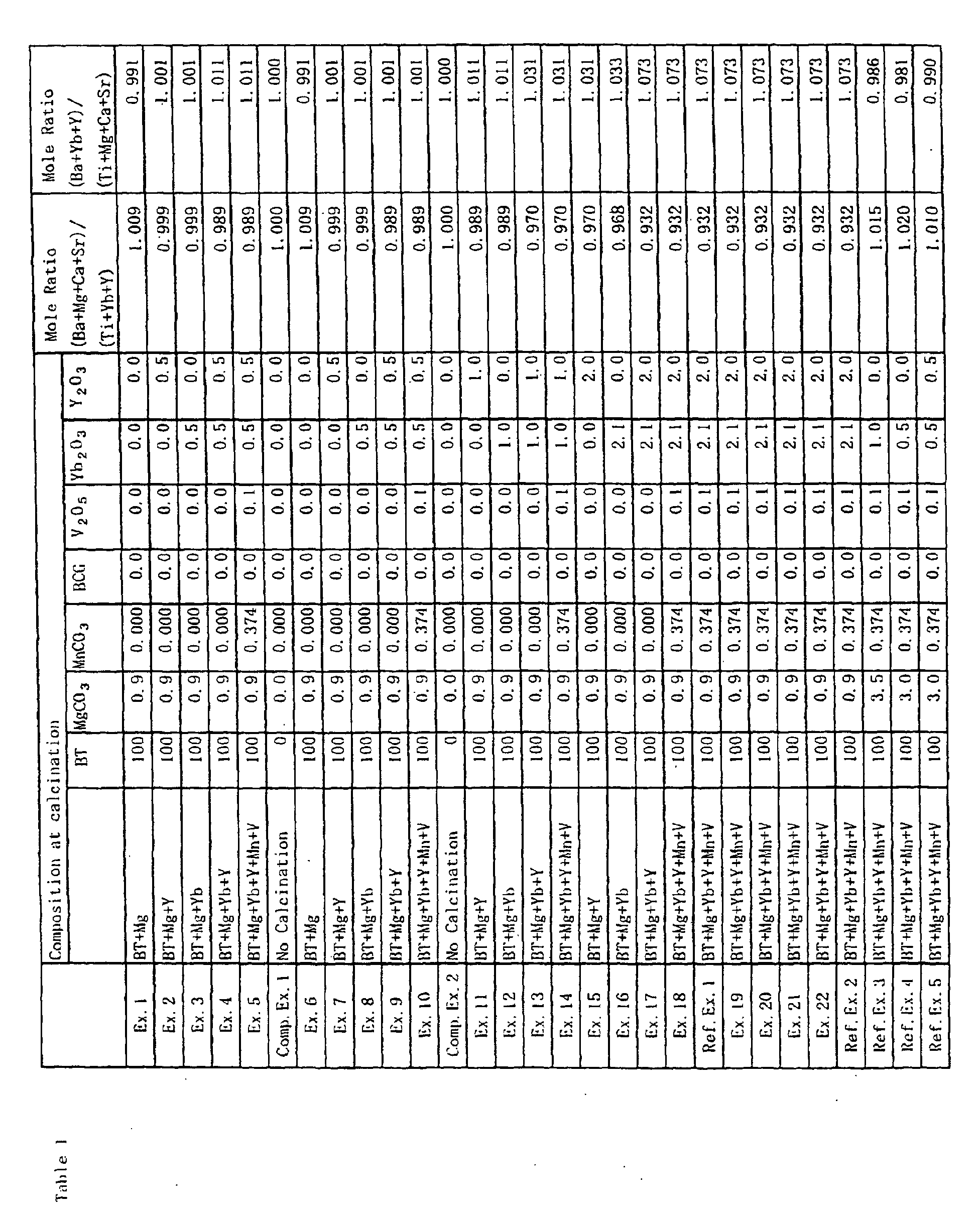
- the pre-calcination powder contained 0.9 mole of MgCO 3 with respect to 100 moles of Ba m TiO 2+m , furthermore, when investigating the molar ratio of a specific component (Ba+Mg+Ca+Sr)/(Ti+Yb+Y) in the pre-calcination powder, it was 1.009 as shown in Table 1. While when investigating the molar ratio of (Ba+Yb+Y)/(Ti+Mg+Ca+Sr), it was 0.991 as shown in Table 1.
- Ni particles of an average grain diameter of 0.2 to 0.8 ⁇ m 100 parts by weight of Ni particles of an average grain diameter of 0.2 to 0.8 ⁇ m, 40 parts by weight of an organic vehicle (8 parts by weight of ethyl cellulose were dissolved in 92 parts by weight of butyl carbitol) and 10 parts by weight of butyl carbitol were kneaded by using a triple-roll to make a paste.
- the above dielectric layer paste was used to form a green sheet of a thickness of 15 ⁇ m on a PET film.
- the internal electrode paste was printed on the surface of the green sheet, then the sheet was peeled from the PET film of a thickness of 15 ⁇ m and the sheet was removed from the PET film.
- four layers of the green sheets printed with the internal electrode paste were stacked over a plurality of protective green sheets (those without the internal electrode layer paste printed on it) and pressed to obtain a green chip.
- the green chip was cut to a predetermined size, then processed to remove the binder, fired, and annealed under the following conditions, then formed with external electrodes to obtain samples of the multilayer ceramic capacitors of the configuration shown in Fig. 1.
- the external electrodes were formed by polishing the end faces of the fired body by sandblasting, then transferring the above external electrode paste to the end faces and firing them there in a wet N 2 +H 2 atmosphere at 800°C for 10 minutes.
- the thus obtained samples had a size of 3.2 mm x 1.6 mm x 0.6 mm, four dielectric layers were sandwiched between internal electrode layers, and the dielectric layer had a thickness of 10 ⁇ m.
- the thickness of each internal electrode layer was 1.5 ⁇ m.
- Disk-shaped samples were also prepared in addition to the samples of the capacitors. These disk-shaped samples were of the same compositions of the dielectric layer of the above capacitors and were fired under the same conditions. In-Ga electrodes of diameters of 5 mm were coated on the two surfaces of the samples.
- the samples were evaluated as to the following characteristics.
- a capacitance and tanD of the disk-shaped samples were measured at 25°C by an LCR meter under conditions of 1 kHz and 1 Vrms. Further, the specific permittivity was calculated from the capacitance, electrode dimensions, and thickness of the samples. The results are shown in Table 3. The higher the specific permittivity the better. The lower the dielectric loss the better.
- the breakdown voltage was found by applying a DC voltage to the samples of the multilayer chip capacitors having four layers at a speed of temperature rise of 100V/sec. and measuring the voltage at the time that a leakage current of 100 mA was observed. The results are shown in Table 3. The higher the breakdown voltage, the better.
- Pre-calcination powder was prepared by mixing BaTiO 3 as a main component, MgCO 3 as an ingredient of a first subcomponent and Y 2 O 3 as a fifth subcomponent and drying them. As shown in Table 1, the pre-calcination powder contained 0.9 mole of MgCO 3 and 0.5 mole of Y 2 O 3 with respect to 100 moles of BaTiO 3 . When investigating the molar ratio of a specific component (Ba+Mg+Ca+Sr)/(Ti+Yb+Y) in the pre-calcination powder, it was 0.999 as shown in Table 1. The molar ratio of (Ba+Yb+Y)/(Ti+Mg+Ca+Sr) was found to be 1.001 as shown in Table 1.
- the pre-calcination powder was calcined to prepare cylinder-shaped samples and samples of capacitors in the same way as in the example 1 except that the calcined powder was added 3.0 moles of (Ba 0.6 Ca 0.4 )SiO 3 , 0.374 mole of MnCO 3 , 0.1 mole of V 2 O 5 , 2.1 moles of Yb 2 O 3 and 1.5 moles of Y 2 O 3 as shown in Table 2, and the same tests as in the example 1 were conducted. The results are shown in Table 3 and Fig. 4.
- Pre-calcination powder was prepared by mixing BaTiO 3 as a main component, MgCO 3 as an ingredient of a first subcomponent and Yb 2 O 3 as a fourth subcomponent and drying them. As shown in Table 1, the pre-calcination powder contained 0.9 mole of MgCO 3 and 0.5 mole of Yb 2 O 3 with respect to 100 moles of BaTiO 3 . When investigating the molar ratio of a specific component (Ba+Mg+Ca+Sr)/(Ti+Yb+Y) in the pre-calcination powder, it was 0.999 as shown in Table 1. The molar ratio of (Ba+Yb+Y)/(Ti+Mg+Ca+Sr) was found to be 1.001 as shown in Table 1.
- the pre-calcination powder was calcined to prepare cylinder-shaped samples and samples of capacitors in the same way as in the example 1 except that the calcined powder was added 3.0 moles of (Ba 0.6 Ca 0.4 )SiO 3 , 0.374 mole of MnCO 3 , 0.1 mole of V 2 O 5 , 1.6 moles of Yb 2 O 3 and 2.0 moles of Y 2 O 3 as shown in Table 2, and the same tests as in the example 1 were conducted. The results are shown in Table 3 and Fig. 4.
- Pre-calcination powder was prepared by mixing BaTiO 3 as a main component, MgCO 3 as an ingredient of a first subcomponent, Yb 2 O 3 as a fourth subcomponent and Y 2 O 3 as a fifth subcomponent and drying them.
- the pre-calcination powder contained 0.9 mole of MgCO 3 , 0.5 mole of Yb 2 O 3 and 0.5 mole of Y 2 O 3 with respect to 100 moles of BaTiO 3 .
- the molar ratio of a specific component (Ba+Mg+Ca+Sr)/(Ti+Yb+Y) in the pre-calcination powder it was 0.989 as shown in Table 1.
- the molar ratio of (Ba+Yb+Y)/(Ti+Mg+Ca+Sr) was found to be 1.011 as shown in Table 1.
- the pre-calcination powder was calcined to prepare cylinder-shaped samples and samples of capacitors in the same way as in the example 1 except that the calcined powder was added 3.0 moles of (Ba 0.6 Ca 0.4 )SiO 3 , 0.374 mole of MnCO 3 , 0.1 mole of V 2 O 5 , 1.6 moles of Yb 2 O 3 and 1.5 moles of Y 2 O 3 as shown in Table 2, and the same tests as in the example 1 were conducted. The results are shown in Table 3 and Fig. 4.
- Pre-calcination powder was prepared by mixing BaTiO 3 as a main component, MgCO 3 as an ingredient of a first subcomponent, V 2 O 5 as a third subcomponent, Yb 2 O 3 as a fourth subcomponent, Y 2 O 3 as a fifth subcomponent and MnCO 3 as an ingredient of another subcomponent and drying them.
- the pre-calcination powder contained 0.9 mole of MgCO 3 , 0.37 mole of MnCO 3 , 0.1 mole of V 2 O 5 , and 0.5 mole of Yb 2 O 3 and 0.5 mole of Y 2 O 3 with respect to 100 moles of BaTiO 3 .
- the pre-calcination powder was calcined to prepare cylinder-shaped samples and samples of capacitors in the same way as in the example 1 except that the calcined powder was added 3.0 moles of (Ba 0.6 Ca 0.4 )SiO 3 , 1.6 moles of Yb 2 O 3 and 1.5 moles of Y 2 O 3 as shown in Table 2, and the same tests as in the example 1 were conducted. The results are shown in Table 3 and Fig. 4.
- cylinder-shaped samples and samples of capacitors were prepared in the same way as in the example 1 except that calcination was not performed, 0.9 mole of MgCO 3 , 0.374 mole of MnCO 3 , 3.0 moles of (Ba 0.6 Ca 0.4 )SiO 3 , 0.1 mole of V 2 O 5 , 2.1 moles of Yb 2 O 3 and 2.0 moles of Y 2 O 3 were added to 100 moles of BaTiO 3 as a main component and the obtained mixed powder was subjected to firing. The same tests as in the example 1 were conducted. The results are shown in Table 3 and Fig. 4.
- Pre-calcination powder was prepared by mixing BaTiO 3 as a main component, MgCO 3 as an ingredient of a first subcomponent and Y 2 O 3 as a fifth subcomponent and drying them. As shown in Table 1, the pre-calcination powder contained 0.9 mole of MgCO 3 and 1.0 mole of Y 2 O 3 with respect to 100 moles of BaTiO 3 . When investigating the molar ratio of a specific component (Ba+Mg+Ca+Sr)/(Ti+Yb+Y) in the pre-calcination powder, it was 0.989 as shown in Table 1. The molar ratio of (Ba+Yb+Y)/(Ti+Mg+Ca+Sr) was found to be 1.011 as shown in Table 1.
- the pre-calcination powder was calcined to prepare cylinder-shaped samples and samples of capacitors in the same way as in the example 1 except that the calcined powder was added 3.0 moles of (Ba 0.6 Ca 0.4 )SiO 3 , 0.374 mole of MnCO 3 , 0.1 mole of V 2 O 5 , 2.1 moles of Yb 2 O 3 and 1.0 mole of Y 2 O 3 as shown in Table 2, and the same tests as in the example 1 were conducted. The results are shown in Table 3.
- Pre-calcination powder was prepared by mixing BaTiO 3 as a main component, MgCO 3 as an ingredient of a first subcomponent and Yb 2 O 3 as a fourth subcomponent and drying them. As shown in Table 1, the pre-calcination powder contained 0.9 mole of MgCO 3 and 1.0 mole of Yb 2 O 3 with respect to 100 moles of BaTiO 3 . When investigating the molar ratio of a specific component (Ba+Mg+Ca+Sr)/(Ti+Yb+Y) in the pre-calcination powder, it was 0.989 as shown in Table 1. The molar ratio of (Ba+Yb+Y)/(Ti+Mg+Ca+Sr) was found to be 1.011 as shown in Table 1.
- the pre-calcination powder was calcined to prepare cylinder-shaped samples and samples of capacitors in the same way as in the example 1 except that the calcined powder was added 3.0 moles of (Ba 0.6 Ca 0.4 )SiO 3 , 0.374 mole of MnCO 3 , 0.1 mole of V 2 O 5 , 1.1 moles of Yb 2 O 3 and 2.0 mole of Y 2 O 3 as shown in Table 2, and the same tests as in the example 1 were conducted. The results are shown in Table 3.
- Pre-calcination powder was prepared by mixing BaTiO 3 as a main component, MgCO 3 as an ingredient of a first subcomponent, Yb 2 O 3 as a fourth subcomponent and Y 2 O 3 as a fifth subcomponent and drying them.
- the pre-calcination powder contained 0.9 mole of MgCO 3 , 1.0 mole of Yb 2 O 3 and 1.0 mole of Y 2 O 3 with respect to 100 moles of BaTiO 3 .
- the molar ratio of a specific component (Ba+Mg+Ca+Sr)/(Ti+Yb+Y) in the pre-calcination powder it was 0.970 as shown in Table 1.
- the molar ratio of (Ba+Yb+Y)/(Ti+Mg+Ca+Sr) was found to be 1.031 as shown in Table 1.
- the pre-calcination powder was calcined to prepare cylinder-shaped samples and samples of capacitors in the same way as in the example 1 except that the calcined powder was added 3.0 moles of (Ba 0.6 Ca 0.4 )SiO 3 , 0.374 mole of MnCO 3 , 0.1 mole of V 2 O 5 , 1.1 moles of Yb 2 O 3 and 1.0 mole of Y 2 O 3 as shown in Table 2, and the same tests as in the example 1 were conducted. The results are shown in Table 3.
- Pre-calcination powder was prepared by mixing BaTiO 3 as a main component, MgCO 3 as an ingredient of a first subcomponent, V 2 O 5 as a third subcomponent, Yb 2 O 3 as a fourth subcomponent, Y 2 O 3 as a fifth subcomponent and MnCO 3 as an ingredient of another subcomponent and drying them.
- the pre-calcination powder contained 0.9 mole of MgCO 3 , 0.37 mole of MnCO 3 , 0.1 mole of V 2 O 5 , 1.0 mole of Yb 2 O 3 and 1.0 mole of Y 2 O 3 with respect to 100 moles of BaTiO 3 .
- the pre-calcination powder was calcined to prepare cylinder-shaped samples and samples of capacitors in the same way as in the example 1 except that the calcined powder was added 3.0 moles of (Ba 0.6 Ca 0.4 )SiO 3 , 1.1 moles of Yb 2 O 3 and 1.0 mole of Y 2 O 3 as shown in Table 2, and the same tests as in the example 1 were conducted. The results are shown in Table 3.
- Pre-calcination powder was prepared by mixing BaTiO 3 as a main component, MgCO 3 as an ingredient of a first subcomponent and Y 2 O 3 as a fifth subcomponent and drying them. As shown in Table 1, the pre-calcination powder contained 0.9 mole of MgCO 3 and 2.0 moles of Y 2 O 3 with respect to 100 moles of BaTiO 3 . When investigating the molar ratio of a specific component (Ba+Mg+Ca+Sr)/(Ti+Yb+Y) in the pre-calcination powder, it was 0.970 as shown in Table 1. The molar ratio of (Ba+Yb+Y)/(Ti+Mg+Ca+Sr) was found to be 1.031 as shown in Table 1.
- the pre-calcination powder was calcined to prepare cylinder-shaped samples and samples of capacitors in the same way as in the example 1 except that the calcined powder was-added 3.0 moles of (Ba 0.6 Ca 0.4 )SiO 3 , 0.374 mole of MnCO 3 , 0.1 mole of V 2 O 5 and 2.1 moles of Yb 2 O 3 as shown in Table 2, and the same tests as in the example 1 were conducted. The results are shown in Table 3.
- Pre-calcination powder was prepared by mixing BaTiO 3 as a main component, MgCO 3 as an ingredient of a first subcomponent and Yb 2 O 3 as. a fourth subcomponent and drying them. As shown in Table 1, the pre-calcination powder contained 0.9 mole of MgCO 3 and 2.1 moles of Yb 2 O 3 with respect to 100 moles of BaTiO 3 . When investigating the molar ratio of a specific component (Ba+Mg+Ca+Sr)/(Ti+Yb+Y) in the pre-calcination powder, it was 0.968 as shown in Table 1. The molar ratio of (Ba+Yb+Y)/(Ti+Mg+Ca+Sr) was found to be 1.033 as shown in Table 1.
- the pre-calcination powder was calcined to prepare cylinder-shaped samples and samples of capacitors in the same way as in the example 1 except that the calcined powder was added 3.0 moles of (Ba 0.6 Ca 0.4 )SiO 3 , 0.374 mole of MnCO 3 , 0.1 mole of V 2 O 5 and 2.0 moles of Y 2 O 3 as shown in Table 2, and the same tests as in the example 1 were conducted. The results are shown in Table 3.
- Pre-calcination powder was prepared by mixing BaTiO 3 as a main component, MgCO 3 as an ingredient of a first subcomponent, Yb 2 O 3 as a fourth subcomponent and Y 2 O 3 as a fifth subcomponent and drying them.
- the pre-calcination powder contained 0.9 mole of MgCO 3 , 2.1 moles of Yb 2 O 3 and 2.0 moles of Y 2 O 3 with respect to 100 moles of BaTiO 3 .
- the molar ratio of a specific component (Ba+Mg+Ca+Sr)/(Ti+Yb+Y) in the pre-calcination powder it was 0.932 as shown in Table 1.
- the molar ratio of (Ba+Yb+Y)/(Ti+Mg+Ca+Sr) was found to be 1.073 as shown in Table 1.
- the pre-calcination powder was calcined to prepare cylinder-shaped samples and samples of capacitors in the same way as in the example 1 except that the calcined powder was added 3.0 moles of (Ba 0.6 Ca 0.4 )SiO 3 , 0.374 mole of MnCO 3 and 0.1 mole of V 2 O 5 as shown in Table 2, and the same tests as in the example 1 were conducted. The results are shown in Table 3.
- Pre-calcination powder was prepared by mixing BaTiO 3 as a main component, MgCO 3 as an ingredient of a first subcomponent, V 2 O 5 as a third subcomponent, Yb 2 O 3 as a fourth subcomponent, Y 2 O 3 as a fifth subcomponent and MnCO 3 as an ingredient of another subcomponent and drying them.
- the pre-calcination powder contained 0.9 mole of MgCO 3 , 0.37 mole of MnCO 3 , 0.1 mole of V 2 O 5 , 2.1 moles of Yb 2 O 3 and 2.0 moles of Y 2 O 3 with respect to 100 moles of BaTiO 3 .
- the pre-calcination powder was calcined to prepare cylinder-shaped samples and samples of capacitors in the same way as in the example 1 except that the calcined powder was added 3.0 moles of (Ba 0.6 Ca 0.4 )SiO 3 as shown in Table 2, and the same tests as in the example 1 were conducted. The results are shown in Table 3.
- Pre-calcination powder was prepared by mixing BaTiO 3 as a main component, MgCO 3 as an ingredient of a first subcomponent, V 2 O 5 as a third subcomponent, Yb 2 O 3 as a fourth subcomponent and MnCO 3 as an ingredient of another subcomponent and drying them. As shown in Table 1, the pre-calcination powder contained 3.5 moles of MgCO 3 , 0.37 mole of MnCO 3 , 0.1 mole of V 2 O 5 and 1.0 mole of Yb 2 O 3 with respect to 100 moles of BaTiO 3 .
- the pre-calcination powder was calcined to prepare cylinder-shaped samples and samples of capacitors in the same way as in the example 1 except that the calcined powder was added 3.0 moles of (Ba 0.6 Ca 0.4 )SiO 3 as shown in Table 2 and that the result was subjected to firing at 1280°C, and the same tests as in the example 1 were conducted.
- Table 3 The results are shown in Table 3.
- Pre-calcination powder was prepared by mixing BaTiO 3 as a main component, MgCO 3 as an ingredient of a first subcomponent, V 2 O 5 as a third subcomponent, Yb 2 O 3 as a fourth subcomponent and MnCO 3 as an ingredient of another subcomponent and drying them. As shown in Table 1, the pre-calcination powder contained 3.0 moles of MgCO 3 , 0.37 mole of MnCO 3 , 0.1 mole of V 2 O 5 and 0.5 mole of Yb 2 O 3 with respect to 100 moles of BaTiO 3 .
- the pre-calcination powder was calcined to prepare cylinder-shaped samples and samples of capacitors in the same way as in the example 1 except that the calcined powder was added 3.0 moles of (Ba 0.6 Ca 0.4 )SiO 3 as shown in Table 2, and the same tests as in the example 1 were conducted. The results are shown in Table 3.
- Pre-calcination powder was prepared by mixing BaTiO 3 as a main component, MgCO 3 as an ingredient of a first subcomponent, V 2 O 5 as a third subcomponent, Yb 2 O 3 as a fourth subcomponent, Y 2 O 3 as a fifth subcomponent and MnCO 3 as an ingredient of another subcomponent and drying them.
- the pre-calcination powder contained 3.0 moles of MgCO 3 , 0.37 mole of MnCO 3 , 0.1 mole of V 2 O 5 , 0.5 mole of Yb 2 O 3 and 0.5 mole of Y 2 O 3 with respect to 100 moles of BaTiO 3 .
- the pre-calcination powder was calcined to prepare cylinder-shaped samples and samples of capacitors in the same way as in the example 1 except that the calcined powder was added 3.0 moles of (Ba 0.6 Ca 0.4 )SiO 3 as shown in Table 2, and the same tests as in the example 1 were conducted. The results are shown in Table 3.
- Cylinder-shaped samples and samples of capacitors were prepared in the same way as in the comparative example 1 except that 3.0 moles of mixed powder of Li 2 O-BaO-SiO 2 (molar ratios are 2:4:4) instead of 3.0 moles of BCG was added as a second subcomponent, and the same tests as in the comparative example 1 were conducted. The results are shown in Table 4.
- Cylinder-shaped samples and samples of capacitors were prepared in the same way as in the comparative example 1 except that 3.0 moles of mixed powder of B 2 O 3 -BaO-SiO 2 (molar ratios are 1:4.5:4.5) instead of 3.0 moles of BCG was added as a second subcomponent, and the same tests as in the comparative example 1 were conducted.
- the results are shown in Table 4.
- Cylinder-shaped samples and samples of capacitors were prepared in the same way as in the comparative example 1 except that 3.0 moles of mixed powder of Li 2 O-BaO-SiO 2 (molar ratios are 4:2:4) instead of 3.0 moles of BCG was added as a second subcomponent, and the same tests as in the comparative example 1 were conducted. The results are shown in Table 4.
- the IR lifetime particularly improves when the molar ratio (Ba+Mg+Ca+Sr)/(Ti+Yb+Y) of components contained in the pre-calcination powder was less than 1 and the molar ratio of (Ti+Yb+Y)/(Ba+Mg+Ca+Sr ) was more than 1.
- the IR lifetime particularly improves when the number of moles of the first subcomponent contained in the pre-calcination powder is smaller than the total moles of the fourth and fifth subcomponents (note that the numbers of moles of the fourth and fifth subcomponents were the rate of R1 alone and R2 alone, respectively).
- CaZrO 3 (hereinafter, also referred to as CZ) as a sixth subcomponent was prepared in addition to the composition shown in the example 1.
- CaZrO 3 was produced by mixing CaCO 2 and ZrO 3 by wet mixing by a ball-mill for 16 hours, drying the result, then firing at 1150°C in the air, further performing wet mixing by a ball-mill for 24 hours.
- the CZ was added to pre-calcination powder by an amount of 1 mole together with 3.0 moles of (Ba 0.6 Ca 0.4 )SiO 3 (described as BCG in the table), 0.374 mole of MnCO 3 , 0.1 mole of V 2 O 5 , 1.0 mole of Yb 2 O 3 and 2.0 moles of Y 2 O 3 as shown in Table 6.
- the pre-calcination powder was prepared in the same way as in the example 1 by mixing BaTiO 3 as a main component with MgCO 3 as an ingredient of a first subcomponent and drying the result. As shown in Table 5, the pre-calcination powder contained 0.9 mole of MgCO 3 with respect to 100 moles of BaTiO 3 (described as BT in the table). When investigating the molar ratio of a specific component, (Ba+Mg+Ca)/ (Ti+Zr+Yb+Y) in the pre-calcination powder, it was 1.009 and (Ba+Ca+Yb+Y)/(Ti+Mg+Zr) was 0.991 as shown in Table 5.
- the calcination holding temperature (T1 in Table 6) was 900°C, which was different from that in the example 1 (1000°C).
- the holding temperature at firing (T2 in Table 6) in the present example 101 was different from that in the example 1 (1320°C) and 1300°C as shown in Table 6.
- Pre-calcination powder was prepared by mixing BaTiO 3 as a main component, MgCO 3 as an ingredient of a first subcomponent and CaZrO 3 as a sixth subcomponent and drying them. As shown in Table 5, the pre-calcination powder contained 0.9 mole of MgCO 3 and 1.0 mole of CaZrO 3 with respect to 100 moles of BaTiO 3 . When investigating the molar ratio of a specific component (Ba+Mg+Ca)/(Ti+Zr+Yb+Y) in the pre-calcination powder, it was 1.009, and the molar ratio of (Ba+Ca+Yb+Y)/(Ti+Mg+Zr) was 0.991 as shown in Table 5.
- the pre-calcination powder was calcined to prepare cylinder-shaped samples and samples of capacitors in the same way as in the example 101 except that the calcined powder was added 3.0 moles of (Ba 0.6 Ca 0.4 )SiO 3 , 0.374 mole of MnCO 3 , 0.1 mole of V 2 O 5 , 1.0 mole of Yb 2 O 3 and 2.0 moles of Y 2 O 3 as shown in Table 6, and the same tests as in the example 101 were conducted. The results are shown in Table 7.
- Pre-calcination powder was prepared by mixing BaTiO 3 as a main component, MgCO 3 as an ingredient of a first subcomponent, Y 2 O 3 as a fifth subcomponent and CaZrO 3 as a sixth subcomponent and drying them. As shown in Table 5, the pre-calcination powder contained 0.9 mole of MgCO 3 , 2.0 moles of Y 2 O 3 and 1.0 mole of CaZrO 3 with respect to 100 moles of BaTiO 3 .
- the pre-calcination powder was calcined to prepare cylinder-shaped samples and samples of capacitors in the same way as in the example 101 except that the calcined powder was added 3.0 moles of (Ba 0.6 Ca 0.4 )SiO 3 , 0.374 mole of MnCO 3 , 0.1 mole of V 2 O 5 and 1.0 mole of Yb 2 O 3 as shown in Table 6, and the same tests as in the example 101 were conducted. The results are shown in Table 7.
- Pre-calcination powder was prepared by mixing BaTiO 3 as a main component, MgCO 3 as an ingredient of a first subcomponent, Yb 2 O 3 as a fourth subcomponent and CaZrO 3 as a sixth subcomponent and drying them. As shown in Table 5, the pre-calcination powder contained 0.9 mole of MgCO 3 , 1.0 mole of Yb 2 O 3 and 1.0 mole of CaZrO 3 with respect to 100 moles of BaTiO 3 .
- the pre-calcination powder was calcined to prepare cylinder-shaped samples and samples of capacitors in the same way as in the example 101 except that the calcined powder was added 3.0 moles of (Ba 0.6 Ca 0.4 )SiO 3 , 0.374 mole of MnCO 3 , 0.1 mole of V 2 O 5 and 2.0 moles of Y 2 O 3 as shown in Table 6, and the same tests as in the example 101 were conducted. The results are shown in Table 7.
- Pre-calcination powder was prepared by mixing BaTiO 3 as a main component, MgCO 3 as an ingredient of a first subcomponent, Yb 2 O 3 as a fourth subcomponent, Y 2 O 3 as a fifth subcomponent and CaZrO 3 as a sixth subcomponent and drying them. As shown in Table 5, the pre-calcination powder contained 0.9 mole of MgCO 3 , 1.0 moles of Yb 2 O 3 , 2.0 moles of Y 2 O 3 and 1.0 mole of CaZrO 3 with respect to 100 moles of BaTiO 3 .
- the pre-calcination powder was calcined to prepare cylinder-shaped samples and samples of capacitors in the same way as in the example 101 except that the calcined powder was added 3.0 moles of (Ba 0.6 Ca 0.4 )SiO 3 , 0.374 mole of MnCO 3 and 0.1 mole of V 2 O 5 as shown in Table 6, and the same tests as in the example 101 were conducted. The results are shown in Table 7.
- Pre-calcination powder was prepared by mixing BaTiO 3 as a main component, MgCO 3 as-an ingredient of a first subcomponent, V 2 O 5 as a third subcomponent, Yb 2 O 3 as a fourth subcomponent, Y 2 O 3 as a fifth subcomponent, CaZrO 3 as a sixth subcomponent and MnCO 3 as an ingredient of a seventh subcomponent and drying them.
- the pre-calcination powder contained 0.9 mole of MgCO 3 , 0.374 mole of MnCO 3 , 0.1 mole of V 2 O 5 , 1.0 moles of Yb 2 O 3 , 2.0 moles of Y 2 O 3 and 1.0 mole of CaZrO 3 with respect to 100 moles of BaTiO 3 .
- the molar ratio of a specific component (Ba+Mg+Ca)/( Ti+Zr+Yb+Y) in the pre-calcination powder it was 0.952, and the molar ratio of (Ba+Ca+Yb+Y)/(Ti+Mg+Zr ) was 1.051 as shown in Table 5.
- the pre-calcination powder was calcined to prepare cylinder-shaped samples and samples of capacitors in the same way as in the example 101 except that the calcined powder was added 3.0 moles of (Ba 0.6 Ca 0.4 )SiO 3 as shown in Table 6, and the same tests as in the example 101 were conducted. The results are shown in Table 5.
- Pre-calcination powder was prepared by mixing only BaTiO 3 as a main component and drying them. When investigating the molar ratio of a specific component (Ba+Mg+Ca)/(Ti+Zr+Yb+Y) in the pre-calcination powder, it was 1.000, and the molar ratio of (Ba+Ca+Yb+Y)/(Ti+Mg+Zr) was 1.000 as shown in Table 5.
- the pre-calcination powder was calcined to prepare cylinder-shaped samples and samples of capacitors in the same way as in the example 101 except that the calcined powder was added 3.0 moles of (Ba 0.6 Ca 0.4 )SiO 3 , 0.9 mole of MgCO 3 , 0.374 mole of MnCO 3 and 0.1 mole of V 2 O 5 , 1.0 mole of Yb 2 O 3 , 2.0 moles of Y 2 O 3 and 1.0 mole of CaZrO 3 as shown in Table 6, and the same tests as in the example 101 were conducted. The results are shown in Table 7.
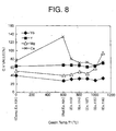
- the degree of dispersion of the additives (Yb, Y, Mg and Ca) in the calcined powder is shown in Fig. 8.
- a TEM observation image of the calcined powder in the present example is shown in Fig. 13.
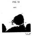
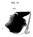
- the C.V value (%) indicating the degree of dispersion indicates that the lower the value the better the degree of dispersion in Fig. 8.
- the TEM observation image was taken by using a product number JEM-3010 made by JEOL Ltd. Note that a sample for TEM observation was produced by dispersing the powder sample in ethanol, then dropping on a microgrid, and drying the result.
- Fig. 8 the degree of dispersion of the additives (Yb, Y, Mg and Ca) in the mixed powder before firing in the comparative example 101 is shown in Fig. 8. Also, a TEM observation image of the mixed powder before firing in the comparative example 101 is shown in Fig. 9.
- Pre-calcination powder (not containing CZ) was prepared by mixing BaTiO 3 as a main component, MgCO 3 as an ingredient of a first subcomponent and (Ba 0.6 Ca 0.4 )SiO 3 as a second subcomponent and drying them. As shown in Table 5, the pre-calcination powder contained 0.9 mole of MgCO 3 and 3.0 moles of (Ba 0.6 Ca 0.4 )SiO 3 with respect to 100 moles of BaTiO 3 .
- the pre-calcination powder was calcined to prepare cylinder-shaped samples and samples of capacitors in the same way as in the example 101 except that the calcined powder was added 3.0 moles of (Ba 0.6 Ca 0.4 )SiO 3 , 0.374 mole of MnCO 3 , 0.1 mole of V 2 O 5 , 1.0 mole of Yb 2 O 3 and 2.0 moles of Y 2 O 3 (CZ was not contained) as shown in Table 6, and the same tests as in the example 101 were conducted. The results are shown in Table 7.
- Fig. 8 the degree of dispersion of the additives (Yb, Y, Mg and Ca) in the calcined powder in the reference example is shown in Fig. 8. Also, a TEM observation image of the calcined powder in the reference example 101 is shown in Fig. 10.
- Fig. 8 the degree of dispersion of the additives (Yb, Y, Mg and Ca) in the calcined powder in the present example is shown in Fig. 8. Also, a TEM observation image of the calcined powder in the present example is shown in Fig. 11.
- Fig. 8 the degree of dispersion of the additives (Yb, Y, Mg and Ca) in the calcined powder in the present example is shown in Fig. 8. Also, a TEM observation image of the calcined powder in the present example is shown in Fig. 12.
- Fig. 8 the degree of dispersion of the additives (Yb, Y, Mg and Ca) in the calcined powder in the present example is shown in Fig. 8. Also, a TEM observation image of the calcined powder in the present example is shown in Fig. 14.
- Fig. 8 the degree of dispersion of the additives (Yb, Y, Mg and Ca) in the calcined powder in the present example is shown in Fig. 8. Also, a TEM observation image of the calcined powder in the present example is shown in Fig. 15.
- Pre-calcination powder was prepared by mixing BaTiO 3 as a main component, MgCO 3 as an ingredient of a first subcomponent, V 2 O 5 as a third subcomponent, Yb 2 O 3 as a fourth subcomponent and MnCO 3 as an ingredient of a seventh subcomponent and drying them. As shown in Table 5, the pre-calcination powder contained 3.5 moles of MgCO 3 , 0.374 mole of MnCO 3 , 0.1 mole of V 2 O 5 and 1.0 mole of Yb 2 O 3 with respect to 100 moles of BaTiO 3 .
- the pre-calcination powder was calcined at 1000°C to prepare cylinder-shaped samples and samples of capacitors in the same way as in the example 101 except that the calcined powder was added 3.0 moles of (Ba 0.6 Ca 0.4 )SiO 3 and 1.0 mole of CaZrO 3 as shown in Table 6 and subjected to firing at 1320 °C, and the same tests as in the example 101 were conducted. The results are shown in Table 5.
- Pre-calcination powder was prepared by mixing BaTiO 3 as a main component, MgCO 3 as an ingredient of a first subcomponent, V 2 O 5 as a third subcomponent, Yb 2 O 3 as a fourth subcomponent and MnCO 3 as an ingredient of a seventh subcomponent and drying them. As shown in Table 5, the pre-calcination powder contained 3.0 moles of MgCO 3 , 0.374 mole of MnCO 3 , 0.1 mole of V 2 O 5 and 0.5 mole of Yb 2 O 3 with respect to 100 moles of BaTiO 3 .
- the pre-calcination powder was calcined at 1000°C to prepare cylinder-shaped samples and samples of capacitors in the same way as in the above example 101 except that the calcined powder was added 3.0 moles of (Ba 0.6 Ca 0.4 )SiO 3 and 1.0 mole of CaZrO 3 as shown in Table 6 and subjected to firing at 1320°C, and the same tests as in the example 101 were conducted. The results are shown in Table 5.
- Pre-calcination powder was prepared by mixing BaTiO 3 as a main component, MgCO 3 as an ingredient of a first subcomponent, V 2 O 5 as a third subcomponent, Yb 2 O 3 as a fourth subcomponent, Y 2 O 3 as a fifth subcomponent and MnCO 3 as an ingredient of a seventh subcomponent and drying them.
- the pre-calcination powder contained 3.0 moles of MgCO 3 , 0.374 mole of MnCO 3 , 0.1 mole of V 2 O 5 , 0.5 mole of Yb 2 O 3 and 0.5 mole of Y 2 O 3 with respect to 100 moles of BaTiO 3 .
- the pre-calcination powder was calcined at 1000°C to prepare cylinder-shaped samples and samples of capacitors in the same way as in the example 101 except that the calcined powder was added 3.0 moles of (Ba 0.6 Ca 0.4 )SiO 3 and 1.0 mole of CaZrO 3 as shown in Table 6 and subjected to firing at 1320°C, and the same tests as in the example 101 were conducted. The results are shown in Table 5.
- a plurality of samples of capacitors having dielectric layers constituted by a dielectric ceramic composition having a different content of CaZrO 3 were prepared in the same way as in the example 101 except that 1.0 mole of MgCO 3 as an ingredient of a first subcomponent, 3.0 moles of (Ba 0.6 Ca 0.4 )SiO 3 as a second subcomponent, 0.1 mole of V 2 O 5 as a third subcomponent, 2.13 moles of Yb 2 O 3 as a fourth subcomponent, 2.0 moles of Y 2 O 3 as a fifth subcomponent, 0 to 6.0 moles of CaZrO 3 as a sixth subcomponent and MnCO 3 as an ingredient of a seventh subcomponent were used with respect to 100 moles of BaTiO 3 as a main component and that calcination was not performed.
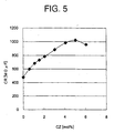
- CR product of the thus obtained samples were obtained in the same way as in the example 101. Relationship of the content of CaZrO 3 and the CR product is shown in Fig. 5. as shown in Fig. 5, it was confirmed that a range of CZ is preferably 0 to 5 moles (note that 0 is not included).
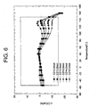
- a plurality of samples of capacitors having dielectric layers constituted by a dielectric ceramic composition having a different content of CaZrO 3 in a range of 0.5 to 5.0 moles were prepared in the same way as in the reference example 103, a capacitance in a temperature range of -55 to 160°C was measured to investigate if the X8R characteristic was satisfied. As shown in Fig. 6, it was confirmed that the X8R characteristic was satisfied when CZ is in the range of 0.5 to 5 moles. Note that a block range wherein the X8R characteristic is satisfied is also indicated in Fig. 6.
- Cylinder-shaped samples and samples of capacitors were prepared in the same way as in the above comparative example 101 except that 3.0 moles of mixed powder of Li 2 O-BaO-SiO 2 (molar ratios are 4:2:4) instead of 3.0 moles of BCG - was added as a second subcomponent, and the same tests as in the comparative example 101 were conducted.
- the results are shown in Table 8.
- the calcination temperature was preferably 700 to 1100°C.
- the IR lifetime characteristic was improved when a rare-earth element (Y or Yb, etc.) was contained at the time of calcination. It was also confirmed that the IR lifetime characteristic was improved by essentially using Y 2 O 3 as a fifth subcomponent than using Yb 2 O 3 as a fourth subcomponent at the time of calcination.
- the present invention it is possible to produce highly reliable dielectric ceramic composition able to be used as a dielectric ceramic composition for a multilayer chip capacitor, etc., wherein base metals, such as Ni, Ni alloy, etc., can be used as internal electrodes, segregation of a different phase other than the main composition can be suppressed, the fine configuration of a dielectric is controlled, the capacitance-temperature characteristic can satisfy the X8R characteristic, and the dielectric loss, CR product and IR lifetime are improved.
- base metals such as Ni, Ni alloy, etc.
Landscapes
- Engineering & Computer Science (AREA)
- Chemical & Material Sciences (AREA)
- Ceramic Engineering (AREA)
- Materials Engineering (AREA)
- Manufacturing & Machinery (AREA)
- Power Engineering (AREA)
- Structural Engineering (AREA)
- Organic Chemistry (AREA)
- Inorganic Chemistry (AREA)
- Microelectronics & Electronic Packaging (AREA)
- Compositions Of Oxide Ceramics (AREA)
- Inorganic Insulating Materials (AREA)
Abstract
Description
said second subcomponent contains SiO2 as a main component and at least one type selected from MO (note that M is at least one type of element selected from Ba, Ca, Sr and Mg), Li2O and B2O3.
said other subcomponents comprise at least
said other subcomponents comprise at least
- the first subcomponent: 0.1 to 3 moles,
- the second subcomponent: 2 to 10 moles,
- the third subcomponent: 0.01 to 0.5 mole,
- the fourth subcomponent: 0.5 to 7 moles (wherein the number of moles of the fourth subcomponent is the ratio of R1 by itself);
- the fifth subcomponent: 2 to 9 moles (wherein the number of moles of the fifth subcomponent is the ratio of R2 by itself); and
- the sixth subcomponent: 0 to 5 moles (note that 0 is not included).
| Composition of components additionally added at time of coating | |||||||||
| T1 | BT | MgCO3 | MnCO3 | BCG | V2O5 | Yb2O3 | Y2O3 | T2 | |
| Ex. 1 | 1000 | 0 | 0.0 | 0.374 | 3.0 | 0.1 | 2.1 | 2.0 | 1320 |
| Ex. 2 | 0 | 0.0 | 0.374 | 3.0 | 0.1 | 2.1 | 1.5 | ||
| Ex. 3 | 0 | 0.0 | 0.374 | 3.0 | 0,1 | 1.6 | 2.0 | ||
| Ex. 4 | 0 | 0.0 | 0.374 | 3.0 | 0.1 | 1.6 | 1.5 | ||
| Ex. 5 | 0 | 0.0 | 0.000 | 3.0 | 0.0 | 1.6 | 1.5 | ||
| Comp. Ex. 1 | 100 | 1.0 | 0.374 | 3.0 | 0.1 | 2.1 | 2.0 | ||
| Ex. 6 | 1000 | 0 | 0.0 | 0.374 | 3.0 | 0.1 | 2.1 | 2.0 | 1340 |
| Ex. 7 | 0 | 0.0 | 0.374 | 3.0 | 0.1 | 2.1 | 1.5 | ||
| Ex. 8 | 0 | 0.0 | 0.374 | 3.0 | 0.1 | 1.6 | 2.0 | ||
| Ex. 9 | 0 | 0.0 | 0.374 | 3.0 | 0.1 | 1.6 | 1.5 | ||
| Ex. 10 | 0 | 0.0 | 0.000 | 3.0 | 0.0 | 1.6 | 1.5 | ||
| Comp. Ex. 2 | 100 | 1.0 | 0.374 | 3.0 | 0.1 | 2.1 | 2.0 | ||
| Ex. 11 | 1000 | 0 | 0.0 | 0.374 | 3.0 | 0.1 | 2.1 | 1.0 | 1320 |
| Ex. 12 | 0 | 0.0 | 0.374 | 3.0 | 0.1 | 1.1 | 2.0 | ||
| Ex. 13 | 0 | 0.0 | 0.374 | 3.0 | 0.1 | 1.1 | 1.0 | ||
| Ex. 14 | 0 | 0.0 | 0.000 | 3.0 | 0.0 | 1.1 | 1.0 | ||
| Ex. 15 | 1000 | 0 | 0.0 | 0.374 | 3.0 | 0.1 | 2.1 | 0.0 | 1320 |
| Ex. 16 | 0 | 0.0 | 0.374 | 3.0 | 0.1 | 0.0 | 2.0 | ||
| Ex. 17 | 0 | 0.0 | 0.374 | 3.0 | 0.1 | 0.0 | 0.0 | ||
| Ex. 18 | 0 | 0.0 | 0.000 | 3.0 | 0.0 | 0.0 | 0.0 | ||
| Ref. Ex. 1 | 600 | 0 | 0.0 | 0.000 | 3.0 | 0.0 | 0.0 | 0.0 | 1320 |
| Ex. 19 | 700 | 0 | 0.0 | 0.000 | 3.0 | 0.0 | 0.0 | 0.0 | |
| Ex. 20 | 800 | 0 | 0.0 | 0.000 | 3.0 | 0.0 | 0.0 | 0.0 | |
| Ex. 21 | 900 | 0 | 0.0 | 0.000 | 3.0 | 0.0 | 0.0 | 0.0 | |
| Ex. 22 | 1100 | 0 | 0.0 | 0.000 | 3.0 | 0.0 | 0.0 | 0.0 | |
| Ref. Ex. 2 | 1200 | 0 | 0.0 | 0.000 | 3.0 | 0.0 | 0.0 | 0.0 | |
| Ref. Ex. 3 | 1000 | 0 | 0.0 | 0.000 | 3.0 | 0.0 | 0.0 | 0.0 | 1280 |
| Ref. Ex. 4 | 1000 | 0 | 0.0 | 0.000 | 3.0 | 0.0 | 0.0 | 0.0 | 1320 |
| Ref. Ex. 5 | 1000 | 0 | 0.0 | 0.000 | 3.0 | 0.0 | 0.0 | 0.0 | 1320 |
| εr (1kHz) [ ] | tanD (1kHz) [%] | ρ [Ω·cm] | CR Product [MΩ µ F] | VB [V] | | |
| Ex. 1 | 1859 | 0.52 | 3.3E+12 | 550 | 1082 | 18.5 |
| Ex. 2 | 1994 | 0.48 | 4.2E+12 | 737 | 1221 | 66.6 |
| Ex. 3 | 1953 | 0.57 | 2.4E+12 | 416 | 993 | 55.3 |
| Ex. 4 | 1919 | 0.50 | 3.4E+12 | 570 | 1215 | 97.0 |
| Ex. 5 | 2022 | 0.50 | 3.6E+12 | 653 | 858 | 107.2 |
| Comp. Ex. 1 | 1944 | 0.48 | 3.4E+12 | 583 | 797 | 53.1 |
| Ex. 6 | 1753 | 0.47 | 3.6E+12 | 598 | 861 | 30.0 |
| Ex. 7 | 2068 | 0.48 | 4.7E+12 | 867 | 768 | 45.2 |
| Ex. 8 | 1956 | 0.46 | 3.3E+12 | 569 | 807 | 38.7 |
| Ex.9 | 1954 | 0.54 | 4.2E+12 | 724 | 820 | 73.6 |
| Ex. 10 | 2029 | 0.50 | 5.2E+12 | 938 | 774 | 68.4 |
| Comp. Ex. 2 | 2062 | 0.49 | 5.0E+12 | 916 | 615 | 34.8 |
| Ex. 11 | 2051 | 0.50 | 5.2E+12 | 944 | 1201 | 65.0 |
| Ex. 12 | 1944 | 0.51 | 3.4E+12 | 585 | 1005 | 63.4 |
| Ex. 13 | 1922 | 0.50 | 3.6E+12 | 612 | 1215 | 123.0 |
| Ex. 14 | 2061 | 0.49 | 5.2E+12 | 948 | 1205 | 122.4 |
| Ex. 15 | 2071 | 0.50 | 5.2E+12 | 953 | 1309 | 78. 8 |
| Ex. 16 | 1956 | 0.51 | 2.3E+12 | 398 | 1008 | 66.3 |
| Ex. 17 | 1943 | 0.51 | 3.6E+12 | 619 | 1221 | 158.3 |
| Ex. 18 | 2080 | 0.40 | 5.1E+12 | 939 | 1229 | 168.3 |
| Ref. Ex. 1 | 1998 | 0.52 | 5.1E+12 | 902 | 799 | 58.9 |
| Ex. 19 | 2009 | 0.50 | 5.1E+12 | 907 | 1101 | 122.2 |
| Ex. 20 | 2007 | 0.40 | 5.1E+12 | 906 | 1206 | 155.4 |
| Ex. 21 | 2020 | 0.41 | 5.1E+12 | 912 | 1212 | 171.6 |
| Ex. 22 | 2098 | 0.55 | 6.2E+12 | 1151 | 929 | 62.2 |
| Ref. Ex. 2 | 2201 | 0.61 | 6.0E+12 | 1169 | 869 | 21.2 |
| Ref. Ex. 3 | 2073 | 0.76 | 2.1E+13 | 3853 | 950 | 4.3 |
| Ref. Ex. 4 | 2218 | 0.50 | 1.8E+13 | 3533 | 1012 | 10.1 |
| Ref. Ex. 5 | 2068 | 0.52 | 2.1E+13 | 3843 | 1182 | 20.5 |
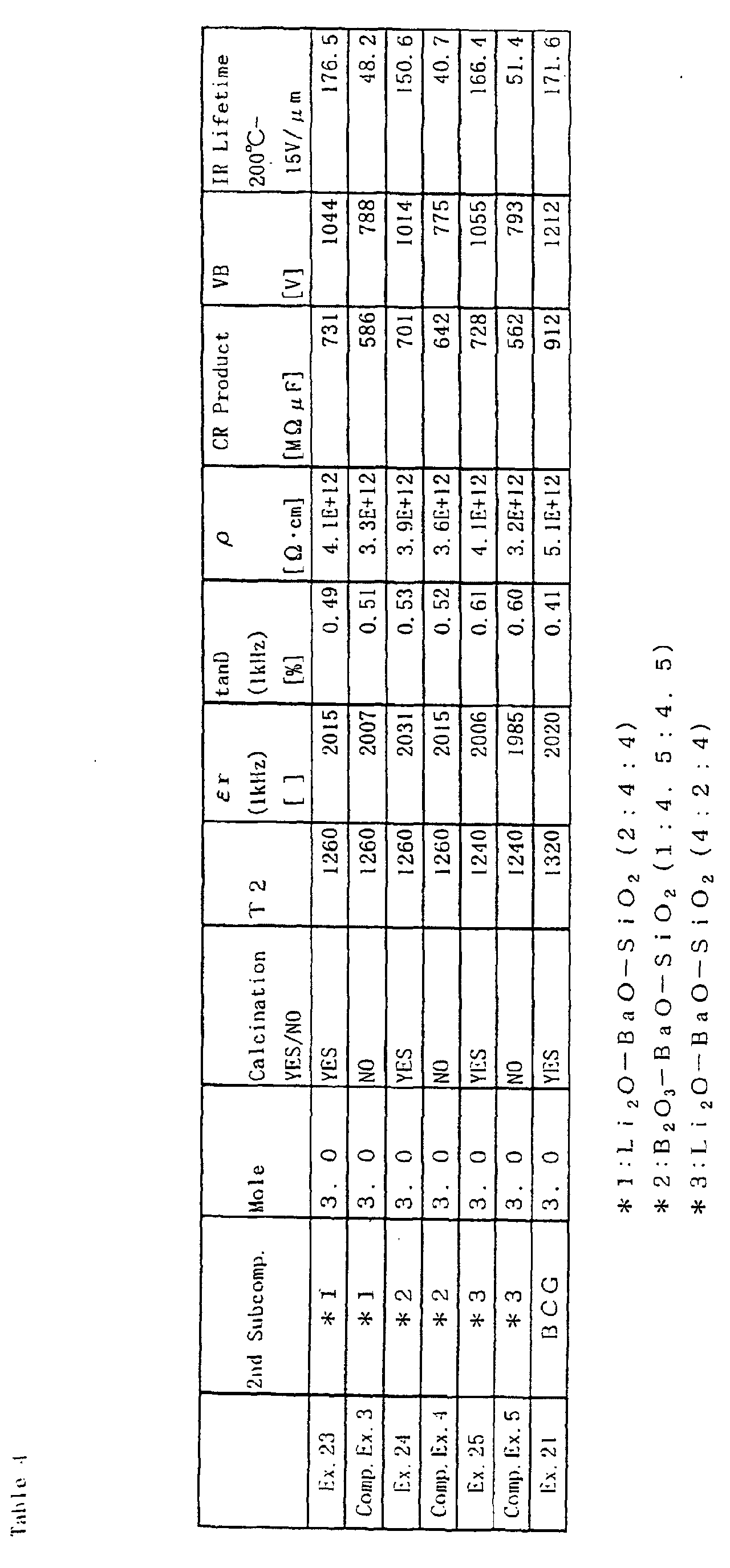
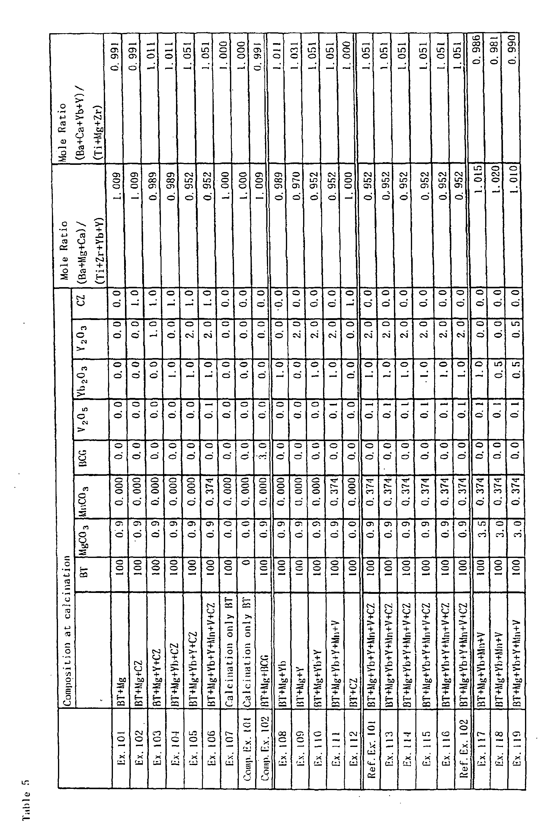
| Composition of components additionally added at time of coating | ||||||||||
| T1 | BT | MgCO3 | MnCO3 | BCG | V2O5 | Yb2O3 | Y2O3 | CZ | T2 | |
| Ex. 101 | 900 | 0 | 0.0 | 0.374 | 3.0 | 0.1 | 1.0 | 2.0 | 1.0 | 1300 |
| Ex. 102 | 900 | 0 | 0.0 | 0.374 | 3.0 | 0.1 | 1.0 | 2.0 | 0.0 | 1300 |
| Ex. 103 | 900 | 0 | 0.0 | 0.374 | 3.0 | 0.1 | 1.0 | 0.0 | 0.0 | 1300 |
| Ex.104 | 900 | 0 | 0.0 | 0.374 | 3.0 | 0.1 | 0.0 | 2.0 | 0.0 | 1300 |
| Ex. 105 | 900 | 0 | 0.0 | 0.374 | 3.0 | 0.1 | 0.0 | 0.0 | 0.0 | 1300 |
| Ex. 106 | 900 | 0 | 0.0 | 0.000 | 3.0 | 0.0 | 0.0 | 0.0 | 0.0 | 1300 |
| Ex. 107 | 900 | 0 | 0.9 | 0.374 | 3.0 | 0.1 | 1.0 | 2.0 | 1.0 | 1300 |
| Camp. Ex. 101 | | 100 | 0.9 | 0.374 | 3.0 | 0.1 | 1.0 | 2.0 | 1.0 | 1300 |
| Comp. Ex. 102 | 900 | 0 | 0.0 | 0.374 | 0.0 | 0.1 | 1.0 | 2.0 | 1.0 | 1300 |
| Ex. 108 | 900 | 0 | 0.0 | 0.374 | 3.0 | 0.1 | 0.0 | 2.0 | 1.0 | 1300 |
| Ex. 109 | 900 | 0 | 0.0 | 0.374 | 3.0 | 0.1 | 1.0 | 0.0 | 1.0 | 1300 |
| Ex. 110 | 900 | 0 | 0.0 | 0.374 | 3.0 | 0.1 | 0.0 | 0.0 | 1.0 | 1300 |
| Ex. 111 | 900 | 0 | 0.0 | 0.000 | 3.0 | 0.0 | 0.0 | 0.0 | 1.0 | 1300 |
| Ex. 112 | 900 | 0 | 0.9 | 0.374 | 3.0 | 0.1 | 1.0 | 2.0 | 0.0 | 1300 |
| Ref. Ex. 101 | 600 | 0 | 0.0 | 0.000 | 3.0 | 0.0 | 0.0 | 0.0 | 1.0 | 1300 |
| Ex. 113 | 700 | 0 | 0.0 | 0.000 | 3.0 | 0.0 | 0.0 | 0.0 | 1.0 | 1300 |
| Ex. 114 | 800 | 0 | 0.0 | 0.000 | 3.0 | 0.0 | 0.0 | 0.0 | 1.0 | 1300 |
| Ex. 115 | 1000 | 0 | 0.0 | 0.000 | 3.0 | 0.0 | 0.0 | 0.0 | 1.0 | 1300 |
| Ex. 116 | 1100 | 0 | 0.0 | 0.000 | 3.0 | 0.0 | 0.0 | 0.0 | 1.0 | 1300 |
| Ref. Ex. 102 | 1200 | 0 | 0.0 | 0.000 | 3.0 | 0.0 | 0.0 | 0.0 | 1.0 | 1300 |
| Ex. 117 | 1000 | 0 | 0.0 | 0.000 | 3.0 | 0.0 | 0.0 | 0.0 | 1.0 | 1320 |
| Ex. 118 | 1000 | 0 | 0.0 | 0.000 | 3.0 | 0.0 | 0.0 | 0.0 | 1.0 | 1320 |
| Ex. 119 | 1000 | 0 | 0.0 | 0.000 | 3.0 | 0.0 | 0.0 | 0.0 | 1.0 | 1320 |
| εr (1kHz) [ ] | tanD (1kHz) [%] | ρ [Ω·cm] | CR Product [MΩ µ F] | VB [V] | | |
| Ex. 101 | 1923 | 0.63 | 4.2E+12 | 715 | 1218 | 39.0 |
| Ex. 102 | 1955 | 0.66 | 3.7E+12 | 640 | 1008 | 78.2 |
| Ex. 103 | 1973 | 0.61 | 3.7E+12 | 646 | 1101 | 198.1 |
| Ex. 104 | 1911 | 0.63 | 3.2E+12 | 541 | 1095 | 180.6 |
| Ex. 105 | 1993 | 0.63 | 2.9E+12 | 512 | 1190 | 240.1 |
| Ex. 106 | 1917 | 0.67 | 3.8E+12 | 645 | 1011 | 364.7 |
| Ex. 107 | 2034 | 0.76 | 3.2E+12 | 576 | 1055 | 73.3 |
| Comp. Ex. 101 | 1915 | 0.69 | 3.9E+12 | 661 | 1088 | 91.5 |
| Camp. Ex. 102 | 1859 | 0.52 | 3.3E+12 | 543 | 1082 | 18.5 |
| Ex. 108 | 1918 | 0.63 | 3.3E+12 | 560 | 1019 | 139.5 |
| Ex. 109 | 1923 | 0.62 | 3.7E+12 | 630 | 1100 | 187.0 |
| Ex. 110 | 1995 | 0.65 | 3.7E+12 | 653 | 1227 | 257.8 |
| Ex. 111 | 1908 | 0.65 | 3.5E+12 | 591 | 1088 | 390.7 |
| Ex. 112 | 2020 | 1.20 | 3.2E+12 | 572 | 1043 | 71.1 |
| Ref. Ex. 101 | 1920 | 0.63 | 3.3E+12 | 561 | 824 | 97.2 |
| Ex. 113 | 1865 | 0.66 | 3.6E+12 | 594 | 996 | 275.5 |
| Ex. 114 | 1872 | 0.59 | 3.5E+12 | 580 | 1095 | 400.3 |
| Ex. 115 | 1915 | 0.61 | 3.5E+12 | 593 | 1100 | 310.6 |
| Ex. 116 | 1987 | 0.73 | 3.4E+12 | 598 | 915 | 121.2 |
| Ref. Ex. 102 | 2089 | 0.72 | 3.7E+12 | 684 | 766 | 60.0 |
| Ex. 117 | 2134 | 0.96 | 1.3E+13 | 246 | 1060 | 3.3 |
| Ex. 118 | 2288 | 0.55 | 1.2E+13 | 243 | 1102 | 8.1 |
| Ex. 119 | 2008 | 0.65 | 1.1E+13 | 195 | 1173 | 10.5 |
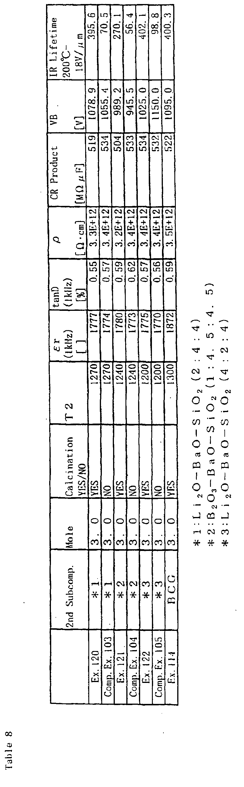
Claims (22)
- A method of manufacturing a dielectric ceramic composition, including at leasta main component constituted by barium titanate;a second subcomponent as a sintering aid; andother subcomponents;comprising the steps of:mixing in said main component at least part of other subcomponents except for the second subcomponent to prepare a pre-calcination powder;calcining said pre-calcination powder to prepare a calcined powder; andmixing at least said second subcomponent in said calcined powder to obtain a dielectric ceramic composition having ratios of the subcomponents to the main component of predetermined molar ratios.
- The method of manufacturing a dielectric ceramic composition as set forth in claim 1, wherein:said barium titanate as the main component has a composition expressed by BamTiO2+m where m is 0.995≤m≤1.010 and the ratio of Ba and Ti is 0.995≤Ba/Ti≤1.010;said second subcomponent contains SiO2 as a main component and at least one type selected from MO (note that M is at least one type of element selected from Ba, Ca, Sr and Mg), Li2O and B2O3;said other subcomponents comprise at leasta first subcomponent containing at least one type selected from MgO, CaO, BaO, SrO and Cr2O3;a third subcomponent containing at least one type selected from V2O5, MoO3 and WO3; anda fourth subcomponent containing an oxide of R1 (note that R1 is at least one type selected from Sc, Er, Tm, Yb and Lu); andinto said calcined powder is mixed at least said second subcomponent so that the ratios of the respective subcomponents with respect to 100 moles of said main component are:the first subcomponent: 0.1 to 3 moles,the second subcomponent: 2 to 10 moles,the third subcomponent: 0.01 to 0.5 mole, andthe fourth subcomponent: 0.5 to 7 moles (wherein the number of moles of the fourth subcomponent is the ratio of R1 by itself).
- The method of manufacturing a dielectric ceramic composition as set forth in claim 2, wherein said pre-calcination powder is prepared so that the molar ratio of components contained in said pre-calcination powder (Ba + metal element of the first subcomponent)/(Ti + metal element of the fourth subcomponent) is less than 1, or (Ba + metal element of the fourth subcomponent)/(Ti + metal element of the first subcomponent) is over 1, and calcination is performed.
- The method of manufacturing a dielectric ceramic composition as set forth in claim 1, wherein:said second subcomponent contains SiO2 as a main component and at least one type selected from. MO (note that M is at least one type of element selected from Ba, Ca, Sr and Mg), Li2O and B2O3;said other subcomponents comprise at leasta first subcomponent containing at least one type selected from MgO, CaO, BaO, SrO and Cr2O3;a third subcomponent containing at least one type selected from V2O5, MoO3 and WO3; anda fourth subcomponent containing an oxide of R1 (note that R1 is at least one type selected from Sc, Er, Tm, Yb and Lu); anda fifth subcomponent containing an oxide of R2 (note that R2 is at least one type selected from Y, Dy, Ho, Tb, Gd and Eu); andinto said calcined powder is mixed at least said second subcomponent so that the ratios of the respective subcomponents with respect to 100 moles of said main component are:the first subcomponent: 0.1 to 3 moles,the second subcomponent: 2 to 10 moles,the third subcomponent: 0.01 to 0.5 mole,the fourth subcomponent: 0.5 to 7 moles, (wherein the number of moles of the fourth subcomponent is the ratio of R1 by itself); andthe fifth subcomponent: 2 to 9 moles, (wherein the number of moles of the fifth subcomponent is the ratio of R2 by itself).
- The method of manufacturing a dielectric ceramic composition as set forth in claim 4, wherein said pre-calcination powder is prepared so that the molar ratio of components contained in said pre-calcination powder (Ba + metal element of the first subcomponent)/(Ti + metal element of the fourth subcomponent + metal element of the fifth subcomponent) is less than 1, or (Ba + metal element of the fourth subcomponent + metal element of the fifth subcomponent)/(Ti + metal element of the first subcomponent) is over 1, and calcination is performed.
- The method of manufacturing a dielectric ceramic composition as set forth in claim 4, wherein said main component and at least one of said first subcomponent, third subcomponent, fourth subcomponent and fifth subcomponent except for the second subcomponent are mixed, and the fifth subcomponent is always contained in pre-calcination powder when preparing the pre-calcination powder.
- The method of manufacturing a dielectric ceramic composition as set forth in claim 4, wherein said main component and at least one of said first subcomponent, third subcomponent, fourth subcomponent and fifth subcomponent except for the second subcomponent are mixed, and the fourth subcomponent is not contained in pre-calcination powder when preparing the pre-calcination powder.
- The method of manufacturing a dielectric ceramic composition as set forth in claim 4, wherein said main component and at least one of said first subcomponent, third subcomponent, fourth subcomponent and fifth subcomponent except for the second subcomponent are mixed, and the first subcomponent is always contained in pre-calcination powder when preparing the pre-calcination powder.
- The method of manufacturing a dielectric ceramic composition as set forth in claim 8, wherein the number of moles of the first subcomponent contained in said pre-calcination powder is smaller than the total number of moles of the fourth subcomponent and fifth subcomponent (note that the numbers of moles of the fourth subcomponent and fifth subcomponent are ratios of R1 by itself and R2 by itself, respectively).
- The method of manufacturing a dielectric ceramic composition as set forth in claim 1, wherein said pre-calcination powder is calcined at a temperature of 700 to 1100°C.
- The method of manufacturing a dielectric ceramic composition as set forth in claim 1, wherein said calcination is performed for a plurality of times.
- A method of manufacturing a dielectric ceramic composition, including at leasta main component constituted by barium titanate;a second subcomponent as a sintering aid;a sixth subcomponent containing CaZrO3 or CaO+ZrO2; andother subcomponents;comprising the steps of:mixing in said main component said sixth subcomponent and at least part of other subcomponents except for the second subcomponent to prepare a pre-calcination powder;calcining said pre-calcination powder to prepare a calcined powder; andmixing at least said second subcomponent in said calcined powder to obtain a dielectric ceramic composition having ratios of the subcomponents to the main component of predetermined molar ratios.
- The method of manufacturing a dielectric ceramic composition as set forth in claim 12, wherein:said barium titanate as the main component has a composition expressed by BamTiO2+m where m is 0.995≤m≤1.010 and the ratio of Ba and Ti is 0.995≤Ba/Ti≤1.010;said second subcomponent contains SiO2 as a main component and at least one type selected from MO (note that M is at least one type of element selected from Ba, Ca, Sr and Mg), Li2O and B2O3;said other subcomponents comprise at leasta first subcomponent containing at least one type selected from MgO, CaO, BaO, SrO and Cr2O3;a third subcomponent containing at least one type selected from V2O5, MoO3 and WO3; anda fourth subcomponent containing an oxide of R1 (note that R1 is at least one type selected from Sc, Er, Tm, Yb and Lu); andinto said calcined powder is mixed at least said second subcomponent so that the ratios of the respective subcomponents with respect to 100 moles of said main component are:the first subcomponent: 0.1 to 3 moles,the second subcomponent: 2 to 10 moles,the third subcomponent: 0.01 to 0.5 mole,the fourth subcomponent: 0.5 to 7 moles (wherein the number of moles of the fourth subcomponent is the ratio of R1 by itself); andthe sixth subcomponent: 0 to 5 moles (note that 0 is not included).
- The method of manufacturing a dielectric ceramic composition as set forth in claim 13, wherein said pre-calcination powder is prepared so that the molar ratio of components contained in said pre-calcination powder (Ba + Ca + metal element of the first subcomponent)/(Ti + Zr + R1) is less than 1, or (Ba + Ca + R1)/(Ti + Zr + metal element of the first subcomponent) is over 1, and calcination is performed.
- The method of manufacturing a dielectric ceramic composition as set forth in claim 12, wherein:said barium titanate as the main component has a composition expressed by BamTiO2+m where m is 0.995≤m≤1.010 andtheratio of Ba and Ti is 0.995≤Ba/Ti≤1.010;said second subcomponent contains SiO2 as a main component and at least one type selected from MO (note that M is at least one type of element selected from Ba, Ca, Sr and Mg), Li2O and B2O3;said other subcomponents comprise at leasta first subcomponent containing at least one type selected from MgO, CaO, BaO, SrO and Cr2O3;a third subcomponent containing at least one type selected from V2O5, MoO3 and WO3; anda fourth subcomponent containing an oxide of R1 (note that R1 is at least one type selected from Sc, Er, Tm, Yb and Lu); anda fifth subcomponent containing an oxide of R2 (note that R2 is at least one type selected from Y, Dy, Ho, Tb, Gd and Eu) ; andinto said calcined powder is mixed at least said second subcomponent so that the ratios of the respective subcomponents with respect to 100 moles of said main component are:the first subcomponent: 0.1 to 3 moles,the second subcomponent: 2 to 10 moles, the third subcomponent: 0.01 to 0.5 mole,the fourth subcomponent: 0.5 to 7 moles (wherein the number of moles of the fourth subcomponent is the ratio of R1 by itself);the fifth subcomponent: 2 to 9 moles (wherein the number of moles of the fifth subcomponent is the ratio of R2 by itself); andthe sixth subcomponent: 0 to 5 moles (note that 0 is not included).
- The method of manufacturing a dielectric ceramic composition as set forth in claim 15, wherein said pre-calcination powder is prepared so that the molar ratio of components contained in said pre-calcination powder (Ba + Ca + metal element of the first subcomponent)/(Ti + Zr + R1 + R2) is less than 1, or (Ba + Ca + R1 + R2)/(Ti + Zr + metal element of the first subcomponent) is over 1, and calcination is performed.
- The method of manufacturing a dielectric ceramic composition as set forth in claim 15, wherein said main component and at least one of said first subcomponent, third subcomponent, fourth subcomponent, fifth subcomponent and sixth subcomponent except for the second subcomponent are mixed, and the fifth subcomponent is always contained in pre-calcination powder when preparing the pre-calcination powder.
- The method of manufacturing a dielectric ceramic composition as set forth in claim 15, wherein said main component and at least one of said first subcomponent, third subcomponent, fourth subcomponent, fifth subcomponent and sixth subcomponent except for the second subcomponent are mixed, and the first subcomponent is always contained in pre-calcination powder when preparing the pre-calcination powder.
- The method of manufacturing a dielectric ceramic composition as set forth in claim 15, wherein said main component and at least one of said first subcomponent, third subcomponent, fourth subcomponent, fifth subcomponent and sixth subcomponent except for the second subcomponent are mixed, and the first subcomponent, the fourth subcomponent and the fifth subcomponent are always contained in pre-calcination powder when preparing the pre-calcination powder.
- The method of manufacturing a dielectric ceramic composition as set forth in claim 19, wherein the number of moles of the first subcomponent contained in said pre-calcination powder is smaller than the total number of moles of the fourth subcomponent and fifth subcomponent (note that the numbers of moles of the fourth subcomponent and fifth subcomponent are ratios of R1 by itself and R2 by itself, respectively).
- The method of manufacturing a dielectric ceramic composition as set forth in claim 12, wherein said pre-calcination powder is calcined at a temperature of 700 to 1100°C.
- The method of manufacturing a dielectric ceramic composition as set forth in claim 12, wherein said calcination is perfromed for a pluraliy of times.
Applications Claiming Priority (7)
| Application Number | Priority Date | Filing Date | Title |
|---|---|---|---|
| JP28459199 | 1999-10-05 | ||
| JP28459199 | 1999-10-05 | ||
| JP34215299 | 1999-12-01 | ||
| JP34215299 | 1999-12-01 | ||
| JP2000252586A JP3340722B2 (en) | 1999-10-05 | 2000-08-23 | Method for producing dielectric porcelain composition |
| JP2000252586 | 2000-08-23 | ||
| PCT/JP2000/006902 WO2001025164A1 (en) | 1999-10-05 | 2000-10-04 | Process for producing dielectric ceramic composition |
Publications (3)
| Publication Number | Publication Date |
|---|---|
| EP1146024A1 true EP1146024A1 (en) | 2001-10-17 |
| EP1146024A4 EP1146024A4 (en) | 2005-06-15 |
| EP1146024B1 EP1146024B1 (en) | 2008-12-17 |
Family
ID=27337104
Family Applications (1)
| Application Number | Title | Priority Date | Filing Date |
|---|---|---|---|
| EP00964643A Expired - Lifetime EP1146024B1 (en) | 1999-10-05 | 2000-10-04 | Process for producing a dielectric ceramic composition |
Country Status (6)
| Country | Link |
|---|---|
| US (1) | US6544916B1 (en) |
| EP (1) | EP1146024B1 (en) |
| KR (1) | KR100428962B1 (en) |
| CN (1) | CN1109005C (en) |
| DE (1) | DE60041120D1 (en) |
| WO (1) | WO2001025164A1 (en) |
Cited By (7)
| Publication number | Priority date | Publication date | Assignee | Title |
|---|---|---|---|---|
| EP1577278A1 (en) * | 2004-03-16 | 2005-09-21 | TDK Corporation | Dielectric ceramic composition, multilayer ceramic capcitor and method for manufacturing the same |
| EP1630833A1 (en) * | 2004-08-30 | 2006-03-01 | TDK Corporation | Dielectric ceramic composition and electronic device |
| JP2007254211A (en) * | 2006-03-23 | 2007-10-04 | Tdk Corp | Electronic component, dielectric ceramic composition and method for producing the same |
| US7399724B2 (en) | 2004-12-13 | 2008-07-15 | Tdk Corporation | Electronic device, dielectric ceramic composition and production method of the same |
| EP1867616A3 (en) * | 2006-06-12 | 2009-11-25 | TDK Corporation | Electronic device, dielectric ceramic composition and the production method |
| EP1868218A3 (en) * | 2006-06-12 | 2009-11-25 | TDK Corporation | Electronic device, dielectric ceramic composition and the production method |
| CN114573335A (en) * | 2020-12-01 | 2022-06-03 | 日本化学工业株式会社 | Composition for forming dielectric ceramic and dielectric ceramic material |
Families Citing this family (21)
| Publication number | Priority date | Publication date | Assignee | Title |
|---|---|---|---|---|
| US6727200B2 (en) * | 2000-08-31 | 2004-04-27 | Mra Laboratories, Inc. | High dielectric constant very low fired X7R ceramic capacitor, and powder for making |
| US6723673B2 (en) * | 2000-08-31 | 2004-04-20 | Mra Laboratories, Inc. | High dielectric constant very low fired X7R ceramic capacitor, and powder for making |
| US6734127B2 (en) * | 2001-10-09 | 2004-05-11 | Dong-Hau Kuo | Ceramic materials for capacitors with a high dielectric constant and a low capacitance change with temperature |
| TW569254B (en) * | 2001-11-14 | 2004-01-01 | Taiyo Yuden Kk | Ceramic capacitor and its manufacturing method |
| JP3908723B2 (en) * | 2003-11-28 | 2007-04-25 | Tdk株式会社 | Method for producing dielectric ceramic composition |
| US7316756B2 (en) | 2004-07-27 | 2008-01-08 | Eastman Kodak Company | Desiccant for top-emitting OLED |
| JP4206062B2 (en) * | 2004-08-30 | 2009-01-07 | Tdk株式会社 | Ceramic electronic component and manufacturing method thereof |
| JP4428187B2 (en) * | 2004-10-12 | 2010-03-10 | Tdk株式会社 | Dielectric ceramic composition and electronic component |
| JP4407497B2 (en) * | 2004-11-30 | 2010-02-03 | Tdk株式会社 | Dielectric ceramic composition and electronic component |
| JP2007153631A (en) * | 2005-11-30 | 2007-06-21 | Tdk Corp | Dielectric ceramic composition, electronic component and laminated ceramic capacitor |
| JP4299827B2 (en) * | 2005-12-05 | 2009-07-22 | Tdk株式会社 | Dielectric ceramic composition, electronic component and multilayer ceramic capacitor |
| JP2007230819A (en) * | 2006-02-28 | 2007-09-13 | Tdk Corp | Dielectric ceramic composition, electronic component, and method for producing the same |
| JP2007331957A (en) * | 2006-06-12 | 2007-12-27 | Tdk Corp | Dielectric ceramic composition, electronic component and its production method |
| US7541306B2 (en) * | 2007-01-17 | 2009-06-02 | Ferro Corporation | X8R dielectric composition for use with nickel electrodes |
| US7521390B2 (en) * | 2007-03-05 | 2009-04-21 | Ferro Corporation | Ultra low temperature fixed X7R and BX dielectric ceramic composition and method of making |
| KR100946016B1 (en) * | 2007-11-16 | 2010-03-09 | 삼성전기주식회사 | Dielectric composition for low temperature firing and high temperature insulation resistance and multilayer ceramic capacitor using same |
| JP5109872B2 (en) * | 2008-08-27 | 2012-12-26 | 株式会社村田製作所 | Multilayer ceramic capacitor and manufacturing method thereof |
| WO2011036970A1 (en) | 2009-09-28 | 2011-03-31 | 株式会社村田製作所 | Dielectric ceramic and laminated ceramic capacitor |
| KR20140118557A (en) * | 2013-03-29 | 2014-10-08 | 삼성전기주식회사 | Dielectric composition and multi layer ceramic capacitor comprising the same |
| CN109231985A (en) * | 2018-10-24 | 2019-01-18 | 天津大学 | A kind of preparation method of low-loss X8R type dielectric material |
| WO2024190166A1 (en) * | 2023-03-16 | 2024-09-19 | 太陽誘電株式会社 | Multilayer ceramic capacitor and method for producing multilayer ceramic capacitor |
Family Cites Families (26)
| Publication number | Priority date | Publication date | Assignee | Title |
|---|---|---|---|---|
| JP2505030B2 (en) * | 1988-09-19 | 1996-06-05 | ティーディーケイ株式会社 | High-permittivity porcelain composition for temperature compensation and method for producing the same |
| JPH0779004B2 (en) | 1990-10-31 | 1995-08-23 | 株式会社村田製作所 | Dielectric porcelain composition |
| JP2605986B2 (en) * | 1991-02-19 | 1997-04-30 | 株式会社村田製作所 | Dielectric porcelain composition |
| JPH06243721A (en) | 1991-03-07 | 1994-09-02 | Tdk Corp | Dielectric ceramic composition having high dielectric constant |
| JPH07118431B2 (en) | 1991-03-16 | 1995-12-18 | 太陽誘電株式会社 | Porcelain capacitor and method of manufacturing the same |
| JPH04292458A (en) | 1991-03-18 | 1992-10-16 | Tdk Corp | Dielectric ceramic composition having high dielectric constant |
| JPH04292459A (en) | 1991-03-18 | 1992-10-16 | Tdk Corp | Dielectric ceramic composition having high dielectric constant |
| JP2978580B2 (en) | 1991-03-22 | 1999-11-15 | ティーディーケイ株式会社 | High dielectric constant dielectric porcelain composition |
| JP2958817B2 (en) * | 1991-06-27 | 1999-10-06 | 株式会社村田製作所 | Non-reducing dielectric porcelain composition |
| JPH05109319A (en) | 1991-10-17 | 1993-04-30 | Tdk Corp | High dielectric constant dielectric porcilain composition |
| JP3109056B2 (en) | 1993-10-19 | 2000-11-13 | 三菱化学株式会社 | Breathable resin film |
| JP3269910B2 (en) * | 1994-03-30 | 2002-04-02 | 太陽誘電株式会社 | Porcelain capacitor and method of manufacturing the same |
| JP3326513B2 (en) * | 1994-10-19 | 2002-09-24 | ティーディーケイ株式会社 | Multilayer ceramic chip capacitors |
| JP3161278B2 (en) * | 1995-04-26 | 2001-04-25 | 株式会社村田製作所 | Dielectric porcelain composition |
| JPH0940465A (en) | 1995-07-27 | 1997-02-10 | Kyocera Corp | Ceramic molding composition |
| JPH09157021A (en) * | 1995-12-04 | 1997-06-17 | Fuji Elelctrochem Co Ltd | Method for producing dielectric material for low temperature sintering |
| JP2993425B2 (en) * | 1995-12-20 | 1999-12-20 | 株式会社村田製作所 | Multilayer ceramic capacitors |
| JPH1025157A (en) | 1996-07-08 | 1998-01-27 | Murata Mfg Co Ltd | Dielectric ceramic composition and multilayer capacitor |
| JP3180681B2 (en) * | 1996-07-19 | 2001-06-25 | 株式会社村田製作所 | Multilayer ceramic capacitors |
| JP3783403B2 (en) * | 1997-07-23 | 2006-06-07 | 株式会社村田製作所 | Dielectric ceramic composition and multilayer ceramic capacitor |
| JP4253869B2 (en) * | 1997-12-19 | 2009-04-15 | 日本ケミコン株式会社 | Dielectric porcelain composition, multilayer ceramic capacitor, and method for manufacturing the same |
| JP3466899B2 (en) | 1998-01-08 | 2003-11-17 | 富士通株式会社 | Character recognition device and method, and program storage medium |
| JP3091192B2 (en) * | 1998-07-29 | 2000-09-25 | ティーディーケイ株式会社 | Dielectric porcelain composition and electronic component |
| JP3567759B2 (en) * | 1998-09-28 | 2004-09-22 | 株式会社村田製作所 | Dielectric ceramic composition and multilayer ceramic capacitor |
| JP3760364B2 (en) | 1999-07-21 | 2006-03-29 | Tdk株式会社 | Dielectric porcelain composition and electronic component |
| JP3678073B2 (en) * | 1999-09-07 | 2005-08-03 | 株式会社村田製作所 | Dielectric ceramic composition and multilayer ceramic component |
-
2000
- 2000-10-04 KR KR10-2001-7007054A patent/KR100428962B1/en not_active Expired - Fee Related
- 2000-10-04 DE DE60041120T patent/DE60041120D1/en not_active Expired - Lifetime
- 2000-10-04 EP EP00964643A patent/EP1146024B1/en not_active Expired - Lifetime
- 2000-10-04 WO PCT/JP2000/006902 patent/WO2001025164A1/en not_active Ceased
- 2000-10-04 CN CN00803096A patent/CN1109005C/en not_active Expired - Fee Related
- 2000-10-04 US US09/857,413 patent/US6544916B1/en not_active Expired - Fee Related
Cited By (11)
| Publication number | Priority date | Publication date | Assignee | Title |
|---|---|---|---|---|
| EP1577278A1 (en) * | 2004-03-16 | 2005-09-21 | TDK Corporation | Dielectric ceramic composition, multilayer ceramic capcitor and method for manufacturing the same |
| EP1630833A1 (en) * | 2004-08-30 | 2006-03-01 | TDK Corporation | Dielectric ceramic composition and electronic device |
| US7262146B2 (en) | 2004-08-30 | 2007-08-28 | Tdk Corporation | Dielectric ceramic composition and electronic device |
| EP1916681A1 (en) * | 2004-08-30 | 2008-04-30 | TDK Corporation | Dielectric ceramic composition and electronic device |
| US7399724B2 (en) | 2004-12-13 | 2008-07-15 | Tdk Corporation | Electronic device, dielectric ceramic composition and production method of the same |
| JP2007254211A (en) * | 2006-03-23 | 2007-10-04 | Tdk Corp | Electronic component, dielectric ceramic composition and method for producing the same |
| EP1837316A3 (en) * | 2006-03-23 | 2009-11-25 | TDK Corporation | Electronic device, dielectric ceramic composition and the production method |
| EP1867616A3 (en) * | 2006-06-12 | 2009-11-25 | TDK Corporation | Electronic device, dielectric ceramic composition and the production method |
| EP1868218A3 (en) * | 2006-06-12 | 2009-11-25 | TDK Corporation | Electronic device, dielectric ceramic composition and the production method |
| US7678724B2 (en) | 2006-06-12 | 2010-03-16 | Tdk Corporation | Electronic device, dielectric ceramic composition and the production method |
| CN114573335A (en) * | 2020-12-01 | 2022-06-03 | 日本化学工业株式会社 | Composition for forming dielectric ceramic and dielectric ceramic material |
Also Published As
| Publication number | Publication date |
|---|---|
| EP1146024B1 (en) | 2008-12-17 |
| KR100428962B1 (en) | 2004-04-29 |
| DE60041120D1 (en) | 2009-01-29 |
| KR20010086455A (en) | 2001-09-12 |
| WO2001025164A1 (en) | 2001-04-12 |
| CN1109005C (en) | 2003-05-21 |
| CN1337928A (en) | 2002-02-27 |
| US6544916B1 (en) | 2003-04-08 |
| EP1146024A4 (en) | 2005-06-15 |
Similar Documents
| Publication | Publication Date | Title |
|---|---|---|
| US6544916B1 (en) | Manufacture method of dielectric ceramic composition | |
| EP1094477B1 (en) | Dielectric ceramic composition and electronic device | |
| JP3760364B2 (en) | Dielectric porcelain composition and electronic component | |
| EP1186578B1 (en) | Method of producing a dielectric ceramic composition and method of producing an electronic device containing dielectric layers | |
| US6403513B1 (en) | Dielectric ceramic composition and electronic device | |
| US7585802B2 (en) | Method of producing a dielectric ceramic composition | |
| EP1327616A2 (en) | Dielectric ceramic composition and electronic device | |
| EP1635360B1 (en) | Dielectric ceramic composition and electronic device | |
| JP3340722B2 (en) | Method for producing dielectric porcelain composition | |
| US6764976B2 (en) | Dielectric ceramic composition and electronic device | |
| EP1710817B1 (en) | Electronic device, dielectric ceramic composition, and method of production of the same | |
| KR20060043615A (en) | Dielectric ceramic composition, multilayer ceramic capacitor, and manufacturing method thereof | |
| KR100807774B1 (en) | Laminated ceramic capacitor | |
| JP3340723B2 (en) | Method for producing dielectric porcelain composition | |
| US7498082B2 (en) | Dielectric ceramic composition having specific dispersion of diffusion depth, electronic device, and multilayer ceramic capacitor | |
| EP1096518A1 (en) | Production method for dielectric porcelain composition and production method for dielectric layer-containing electronic parts | |
| JP2003192432A (en) | Dielectric ceramic composition and electronic parts | |
| JP5167579B2 (en) | Dielectric ceramic composition and electronic component | |
| JP4387990B2 (en) | Dielectric ceramic composition and electronic component | |
| JP2005263508A (en) | Dielectric ceramic composition, laminated porcelain capacitor, and method for producing the capacitor | |
| JP2005272263A (en) | Dielectric ceramic composition, multilayer ceramic capacitor and its manufacturing method |
Legal Events
| Date | Code | Title | Description |
|---|---|---|---|
| PUAI | Public reference made under article 153(3) epc to a published international application that has entered the european phase |
Free format text: ORIGINAL CODE: 0009012 |
|
| 17P | Request for examination filed |
Effective date: 20010702 |
|
| AK | Designated contracting states |
Kind code of ref document: A1 Designated state(s): AT BE CH CY DE DK ES FI FR GB GR IE IT LI LU MC NL PT SE |
|
| AX | Request for extension of the european patent |
Free format text: AL;LT;LV;MK;RO;SI |
|
| RBV | Designated contracting states (corrected) |
Designated state(s): DE FR GB NL |
|
| A4 | Supplementary search report drawn up and despatched |
Effective date: 20050428 |
|
| RIC1 | Information provided on ipc code assigned before grant |
Ipc: 7H 01G 4/12 B Ipc: 7C 04B 35/468 A Ipc: 7C 04B 35/50 B |
|
| 17Q | First examination report despatched |
Effective date: 20051010 |
|
| 17Q | First examination report despatched |
Effective date: 20051010 |
|
| 17Q | First examination report despatched |
Effective date: 20051010 |
|
| GRAP | Despatch of communication of intention to grant a patent |
Free format text: ORIGINAL CODE: EPIDOSNIGR1 |
|
| GRAS | Grant fee paid |
Free format text: ORIGINAL CODE: EPIDOSNIGR3 |
|
| RTI1 | Title (correction) |
Free format text: PROCESS FOR PRODUCING A DIELECTRIC CERAMIC COMPOSITION |
|
| GRAA | (expected) grant |
Free format text: ORIGINAL CODE: 0009210 |
|
| AK | Designated contracting states |
Kind code of ref document: B1 Designated state(s): DE FR GB NL |
|
| REG | Reference to a national code |
Ref country code: GB Ref legal event code: FG4D |
|
| REF | Corresponds to: |
Ref document number: 60041120 Country of ref document: DE Date of ref document: 20090129 Kind code of ref document: P |
|
| PG25 | Lapsed in a contracting state [announced via postgrant information from national office to epo] |
Ref country code: NL Free format text: LAPSE BECAUSE OF FAILURE TO SUBMIT A TRANSLATION OF THE DESCRIPTION OR TO PAY THE FEE WITHIN THE PRESCRIBED TIME-LIMIT Effective date: 20081217 |
|
| NLV1 | Nl: lapsed or annulled due to failure to fulfill the requirements of art. 29p and 29m of the patents act | ||
| PLBE | No opposition filed within time limit |
Free format text: ORIGINAL CODE: 0009261 |
|
| STAA | Information on the status of an ep patent application or granted ep patent |
Free format text: STATUS: NO OPPOSITION FILED WITHIN TIME LIMIT |
|
| 26N | No opposition filed |
Effective date: 20090918 |
|
| REG | Reference to a national code |
Ref country code: FR Ref legal event code: ST Effective date: 20100630 |
|
| PG25 | Lapsed in a contracting state [announced via postgrant information from national office to epo] |
Ref country code: FR Free format text: LAPSE BECAUSE OF NON-PAYMENT OF DUE FEES Effective date: 20091102 |
|
| PG25 | Lapsed in a contracting state [announced via postgrant information from national office to epo] |
Ref country code: GB Free format text: LAPSE BECAUSE OF NON-PAYMENT OF DUE FEES Effective date: 20091004 |
|
| PGFP | Annual fee paid to national office [announced via postgrant information from national office to epo] |
Ref country code: DE Payment date: 20100929 Year of fee payment: 11 |
|
| PG25 | Lapsed in a contracting state [announced via postgrant information from national office to epo] |
Ref country code: DE Free format text: LAPSE BECAUSE OF NON-PAYMENT OF DUE FEES Effective date: 20120501 |
|
| REG | Reference to a national code |
Ref country code: DE Ref legal event code: R119 Ref document number: 60041120 Country of ref document: DE Effective date: 20120501 |