EP1145894A2 - Zwillingsreifenanordnung mit variabler Radzuschaltung - Google Patents
Zwillingsreifenanordnung mit variabler Radzuschaltung Download PDFInfo
- Publication number
- EP1145894A2 EP1145894A2 EP01303448A EP01303448A EP1145894A2 EP 1145894 A2 EP1145894 A2 EP 1145894A2 EP 01303448 A EP01303448 A EP 01303448A EP 01303448 A EP01303448 A EP 01303448A EP 1145894 A2 EP1145894 A2 EP 1145894A2
- Authority
- EP
- European Patent Office
- Prior art keywords
- wheel hub
- wheel
- rotational axis
- mechanism according
- engagement
- Prior art date
- Legal status (The legal status is an assumption and is not a legal conclusion. Google has not performed a legal analysis and makes no representation as to the accuracy of the status listed.)
- Granted
Links
Images


Classifications
-
- B—PERFORMING OPERATIONS; TRANSPORTING
- B60—VEHICLES IN GENERAL
- B60K—ARRANGEMENT OR MOUNTING OF PROPULSION UNITS OR OF TRANSMISSIONS IN VEHICLES; ARRANGEMENT OR MOUNTING OF PLURAL DIVERSE PRIME-MOVERS IN VEHICLES; AUXILIARY DRIVES FOR VEHICLES; INSTRUMENTATION OR DASHBOARDS FOR VEHICLES; ARRANGEMENTS IN CONNECTION WITH COOLING, AIR INTAKE, GAS EXHAUST OR FUEL SUPPLY OF PROPULSION UNITS IN VEHICLES
- B60K17/00—Arrangement or mounting of transmissions in vehicles
- B60K17/36—Arrangement or mounting of transmissions in vehicles for driving tandem wheels
Definitions
- This invention relates to an axle assembly having multiple wheels at each end of an axle in which one wheel is permitted to rotate relative to the other wheel, and more specifically, the invention relates to a mechanism for locking the wheels together for driving and/or braking both wheels.
- Axle assemblies having dual wheels on either end of the axle have been used to increase the load bearing capability of heavy duty vehicles.
- the pair of wheels on each end of the axle assembly is secured together so that they rotate together about an axis.
- Some heavy duty vehicles, such as lift trucks, undergo numerous turning maneuvers which wear the tires significantly. The tire wear is caused when the tires scrub, or drag, since the wheels that are secured together must travel different distances at the inside and outside of the turning radius. Tire wear and maintenance on heavy duty lift trucks due to scrub cost thousands of dollars annually per vehicle.
- Dual wheel assembly designs have been proposed that permit the wheels to rotate relative to one another to reduce scrubbing during vehicle turns while driving at least one of the wheels to propel the vehicle.
- Certain driving conditions require that both wheels be driven to provide enough traction to propel the vehicle and its load.
- braking force may be required at both wheels to produce sufficient braking force to stop the loaded vehicle.
- Some designs have been developed which utilize a differential gear set between the wheels so that both wheels may be driven.
- Other designs have provided a second brake assembly slaved off a first brake assembly to provide braking force to both wheels.
- prior art designs do not provide a mechanism that will lock wheels together, which are rotatable relative to one another, for driving and/or braking conditions. Therefore, what is needed is a mechanism that permits the wheels to be selectively locked together to provide increased traction and/or to permit braking force to be applied to both wheels.
- the present invention provides a variable engagement mechanism for a dual wheel assembly.
- the mechanism includes a spindle having a drive axle defining a rotational axis.
- a first wheel hub is supported on the spindle and coupled to the drive axle for being rotatably driven about the rotational axis.
- a second wheel hub is arranged adjacent to the first wheel hub and is rotatable relative to the first wheel hub about the rotational axis.
- the first wheel hub has a support member extending there from along the rotational axis and the second wheel hub is supported on the support member.
- First and second friction discs are adjacent to one another and splined to the first and the second wheel hubs, respectively. An actuator forces the friction discs into engagement with one another to permit transfer of torque between the wheel hubs. In this manner, the first and second wheel hub may be selectively locked together.
- the second wheel hub includes an interlocking member.
- An engagement member is splined to the support member to prevent relative rotation there between and is movable relative to the support member along the rotation axis to an engaged position in which the engagement member engages the interlocking member.
- a first actuator moves the engagement member along the rotational axis to the engaged position for increased traction or braking.
- Friction discs may be used between the engagement member and a housing supported by the spindle to provide a braking force to both wheel hubs when they are coupled together.
- a friction surface is supported on one of the first and the second wheel hubs.
- a friction member is movable toward the friction surface along a second axis.
- a biasing member is interposed between the friction member and the other of the one of the first and the second wheel hubs for forcing the friction member against the friction surface and transferring torque between the wheel hubs.
- the biasing member may be a passive device such as a spring or an actuator such as a hydraulic piston.
- a differential assembly is interconnected between the first wheel hub and the second wheel hub.
- the differential assembly includes a gradual locking mechanism movable between unlocked and locked positions.
- An actuator moves the locking mechanism and locks the first and the second wheel hubs together in the locked position to prevent relative rotation there between. In this manner, both wheels may be driven while the second wheel is permitted to rotate relative to the first wheel.
- the differential may be gradually locked when increased traction or braking is necessary.
- the above inventions provide is a mechanism that permits the wheels to be selectively locked together to provide increased traction and/or to permit braking force to be applied to both wheels.
- the present invention variable engagement mechanisms 10 shown in the Figures are adapted for dual wheel assemblies.
- Each mechanism 10 includes a spindle 12 having a drive axle 14 disposed therein that defines a rotational axis A.
- a first wheel hub 16 is supported on the spindle 12 for rotation about axis A.
- a second wheel hub 18 is adjacent to the first wheel hub 16 and is relatively rotatable thereto about axis A.
- the second wheel hub 18 may be supported by the spindle 12 or some other component in the mechanism 10.
- Bearing assemblies 19 support the wheel hubs 16, 18.
- either the first wheel hub 16 or the second wheel hub 18 may be coupled to the drive axle 14.
- the dual wheel assemblies incorporated a gear reduction assembly 20, for example a planetary gear set, to provide increased torque for heavy load applications, such as lift trucks.
- the present invention may be used without the gear reduction assembly 20.
- the first wheel hub 16 is coupled to the drive axle 14 and is rotatably driven about the rotational axis A.
- the first wheel hub 16 has a support member 22 extending there from along the rotational axis A.
- the support member 22 is a nose that extends from the planetary gear set spider 23.
- the second wheel hub 18 is supported on the support member 22 adjacent to the first wheel hub 16 and is normally undriven.
- First 24 and second 26 friction discs which are adjacent to one another in alternating relationship, are splined to the first 16 and the second 18 wheel hubs, respectively.
- An actuator 30, which may include a piston 32 and cylinder 34, is used to force the friction discs 24, 26 into engagement with one another to permit transfer of torque between the wheel hubs 16, 18.
- the actuator 30 may be actuated in any known manner, such as pneumatically. If the actuator 30 rotates with a wheel hub, as shown, known central tire inflation technology may be used to pneumatically actuate the actuator 30.
- a control unit 40 is coupled to the actuator 30 to lock and unlock the first 16 and second 18 wheel hubs.
- the control unit 40 may be part of a brake unit 42, in which the hubs 16, 18 are locked together when the vehicle brakes are actuated.
- the control unit 40 may be driver controlled so that the driver may lock the hubs 16, 18 together for increased traction and braking when needed, and unlock the hubs 16, 18 during maneuvers that would cause tire scrub.
- the first wheel hub 16 has a support member 22 extending there from, and the second wheel hub 18 is supported on the support member 22.
- the second wheel hub 18 is normally undriven and rotatable relative to the first wheel hub 16 about the rotational axis A.
- the second wheel hub 18 includes an interlocking member 44.
- An engagement member 46 is splined to the support member 22 to prevent relative rotation between the members 44, 46 while permitting the engagement member 46 to move relative to the support member 22 along the rotation axis A.
- the interlocking member 44 includes a plurality of teeth and the engagement member 46 is a dog clutch engageable with the teeth.
- a first actuator 48 moves the engagement member 46 to an engaged position in which the engagement member 46 engages the interlocking member 44 for coupling the first 16 and second 18 wheel hubs together. In this, manner traction may be increased by locking the hubs 16, 18 together.
- the first actuator 48 may be a dual acting piston actuatable between the engaged and disengaged positions. Alternatively, a return spring 50 may be used to move the engagement member 46 to the disengaged position.
- a housing 52 is supported by the spindle 12 with a second actuator 54 disposed within the housing 52.
- the first actuator 48 may also be disposed within the housing 52, as shown in the Figure.
- First 56 and second 58 friction discs which are arranged adjacent to one another, are splined to the housing 52 and the engagement member 46, respectively.
- the second actuator 54 forces the friction discs 56, 58 into engagement with one another in a brake position for braking the first wheel hub 16.
- the control device 40 may be connected to both the first 48 and second 54 actuators or only one of the actuators.
- the first 48 and second 54 actuator may be actuated together when the brakes are actuated so that maximum braking force is applied.
- the first actuator 48 may be actuated by the driver independently of the second actuator 54 so that the vehicle will have maximum traction force.
- FIG. 3 an embodiment of the present invention is shown having the first wheel hub 16 supported on the spindle 12 and coupled to the drive axle 14 for being rotatably driven about the rotational axis A.
- the second wheel hub 18 is adjacent to the first wheel hub 16 and is rotatable relative to the first wheel hub 16 about the rotational axis A.
- a gear reduction assembly is not shown between the hubs 16, 18, one may be used.
- a differential assembly 60 is interconnected between the hubs 16, 18. Any locking differential arrangement may be used.
- the differential assembly 60 includes a differential gear carrier 62 supported on the first wheel hub 16.
- a first differential gear 64 is supported in the carrier 62 transverse to the axis A.
- a second differential gear 66 is engaged with first differential gear 64 and is supported on a shaft 65 that is coaxial with axis A.
- the shaft 65 is connected to the second wheel hub 18 so that as the second differential gear 66 is driven the second wheel hub 18 is rotated.
- both hubs 16, 18 are driven and maximum traction force is provided.
- the differential assembly 60 permits the hubs 16, 18 to rotate relative to one another so that scrub is reduced.
- the differential assembly 60 has a locking mechanism 67 that includes first 68 and second 69 friction discs adjacent to one another and splined to the carrier 62 and the second differential gear 66 via shaft 65.
- the locking mechanism 67 further includes an actuator 70, which is movable between unlocked and locked positions.
- the actuator 70 forces the friction discs 68, 69 into engagement with one another to the locked position. In this manner, the hubs 16, 18 are not permitted to rotate relative to one another during a turn so that maximum traction or braking force may be provided.
- the control device 40 may be configured to permit the driver to selectively actuate the actuator 70.
- a passive locking mechanism 74 is shown.
- the wheel hubs 16, 18 are supported on the spindle 12.
- An annular friction surface 76 is supported on one of the wheel hubs 16, 18, such as hub 18.
- a biasing member 78 such as a spring, is supported by the other wheel hub, which is hub 16 as shown, and forces a friction member 80 into engagement with the friction surface 76.
- the friction member 80 moves along a second axis B that is parallel to the rotational axis A.
- the biasing member 78 generates enough force so that the hubs 16, 18 are locked together when the vehicle is travelling in a straight path.
- the resilient member 78 permits the hubs 16, 18 to rotate relative to one another.
- the passive locking mechanism 74 permits the transfer of torque between the wheel hubs 16, 18 without any driver interaction.
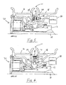
- Figures 5 and 6 depict active locking mechanisms 79.
- the wheel hubs 16, 18 are arranged in a manner similar to Figure 4.
- the first wheel hub 16 includes a rotor 80 having opposing faces 82 that provide friction surfaces. Friction pads 83 are adjacent to each face 82 and are supported in a caliper 84 which is supported on the second wheel hub 18.
- a biasing member 86 such as a pneumatic, hydraulic, or other actuator, is movable between engaged and disengaged positions. Central tire inflation technology may be adapted to actuate the actuator 86 if needed.
- the actuator 86 preferably includes a piston for forcing the friction pads 83 into engagement with the rotor 80 in the engaged position for transferring torque between the wheel hubs 16, 18.
- the control device 40 permits a vehicle operator to selectively actuate the actuator 86. Therefore, the hubs may be locked together to increase traction and/or braking force to the hubs 16, 18.
- the first hub 16 supports a drum 88 that has a friction surface 90.
- Brake shoes 92 (only one shown) are each supported by a pin 93 that extends from the second wheel hub 18.
- An actuator 96 is disposed between the brake shoes 93 for pivoting the brake shoes 92 about pins 93 and forcing the brake shoes 93 into engagement with the drum 88 in the engaged position to transferring torque between the wheel hubs 16, 18.
- the control device 40 permits a vehicle operator to selectively actuate the actuator 96 for situations in which increased traction and/or braking force is desired.
Landscapes
- Engineering & Computer Science (AREA)
- Chemical & Material Sciences (AREA)
- Combustion & Propulsion (AREA)
- Transportation (AREA)
- Mechanical Engineering (AREA)
- Arrangement And Mounting Of Devices That Control Transmission Of Motive Force (AREA)
- Retarders (AREA)
- Tires In General (AREA)
Applications Claiming Priority (2)
| Application Number | Priority Date | Filing Date | Title |
|---|---|---|---|
| US548228 | 1983-11-02 | ||
| US09/548,228 US6527073B1 (en) | 2000-04-12 | 2000-04-12 | Dual wheel assembly with variable wheel engagement |
Publications (3)
| Publication Number | Publication Date |
|---|---|
| EP1145894A2 true EP1145894A2 (de) | 2001-10-17 |
| EP1145894A3 EP1145894A3 (de) | 2004-08-11 |
| EP1145894B1 EP1145894B1 (de) | 2008-08-06 |
Family
ID=24187919
Family Applications (1)
| Application Number | Title | Priority Date | Filing Date |
|---|---|---|---|
| EP01303448A Expired - Lifetime EP1145894B1 (de) | 2000-04-12 | 2001-04-12 | Zwillingsreifenanordnung mit variabler Radzuschaltung |
Country Status (4)
| Country | Link |
|---|---|
| US (1) | US6527073B1 (de) |
| EP (1) | EP1145894B1 (de) |
| AT (1) | ATE403570T1 (de) |
| DE (1) | DE60135171D1 (de) |
Cited By (5)
| Publication number | Priority date | Publication date | Assignee | Title |
|---|---|---|---|---|
| CN103687731A (zh) * | 2011-06-27 | 2014-03-26 | 凯斯勒合资有限公司 | 用于双联轮的轮毂装置 |
| ITMO20130099A1 (it) * | 2013-04-17 | 2014-10-18 | Omci S P A | Accoppiamento di ruote gemellate motrici per un assale motore di un veicolo |
| EP3108155A4 (de) * | 2014-02-18 | 2017-11-01 | AxleTech International IP Holdings, LLC | Systeme und verfahren für verbesserte differentialsperren |
| US9873288B2 (en) | 2015-10-22 | 2018-01-23 | Kessler & Co. Gmbh & Co. Kg | Hub arrangement for twin wheels |
| WO2023172414A3 (en) * | 2022-03-07 | 2023-12-14 | Volley Automation, Inc. | Vehicles including truck assemblies configured to selectively decouple a wheel of the truck assembly |
Families Citing this family (7)
| Publication number | Priority date | Publication date | Assignee | Title |
|---|---|---|---|---|
| US6672985B2 (en) | 2001-08-30 | 2004-01-06 | Axletech International Ip Holdings, Llc | Independently rotating wheels with planetary drive |
| US6890039B2 (en) | 2002-03-06 | 2005-05-10 | Axletech International Ip Holdings, Llc | Independently rotating wheels |
| US7757795B2 (en) * | 2007-06-22 | 2010-07-20 | Axletech International Ip Holdings, Llc | Dual wheelend for a vehicle |
| US8651205B2 (en) | 2009-02-27 | 2014-02-18 | Robert Lee Chess | Direct power reversing drive axle |
| US8596156B2 (en) | 2009-02-27 | 2013-12-03 | Robert David Clark | Vehicle transmission with clutch pack overrun |
| DE102012015199B4 (de) | 2012-08-03 | 2018-02-22 | Kessler & Co. Gmbh & Co. Kg | Nabenanordnung, insbesondere für Zwillingsräder |
| DE102021001884B3 (de) * | 2021-04-01 | 2022-03-03 | Karl Thiel | Bremsausrüstung zur ausrüstung von fahrradanhängern |
Family Cites Families (27)
| Publication number | Priority date | Publication date | Assignee | Title |
|---|---|---|---|---|
| US1975206A (en) | 1931-03-31 | 1934-10-02 | Albert C Fuhrman | Brake for dual wheel organization |
| US2001875A (en) | 1931-09-26 | 1935-05-21 | Stephen A Griggs | Brake |
| US2082292A (en) | 1933-01-09 | 1937-06-01 | George A Kendall | Brake combination for dual trailer wheels and wheel construction |
| US2132029A (en) | 1936-09-28 | 1938-10-04 | James F Higbee | Dual wheel assembly |
| US2135568A (en) | 1936-11-10 | 1938-11-08 | Detroit Compensating Axle Corp | Dual-wheel assembly |
| US2213383A (en) | 1937-05-20 | 1940-09-03 | Differential Wheel Corp | Dual wheeled vehicle |
| US2237547A (en) * | 1938-07-02 | 1941-04-08 | Differential Wheel Corp | Dual wheel vehicle |
| US2192023A (en) | 1938-07-29 | 1940-02-27 | Charles S Ash | Dual wheel vehicle brake |
| US2222695A (en) * | 1938-08-22 | 1940-11-26 | Differential Wheel Corp | Dual wheel drive and brake mechanism |
| US2260828A (en) | 1939-04-17 | 1941-10-28 | Clark Equipment Co | Wheel |
| US2267362A (en) | 1940-06-08 | 1941-12-23 | Charles S Ash | Dual wheel assembly |
| US2281541A (en) * | 1940-09-12 | 1942-05-05 | Charles S Ash | Dual wheel assembly |
| US2355133A (en) * | 1940-10-12 | 1944-08-08 | Charles S Ash | Dual wheel assembly |
| US2398348A (en) | 1942-01-28 | 1946-04-16 | Charles S Ash | Dual wheel vehicle |
| US2397673A (en) | 1943-03-04 | 1946-04-02 | Frank M Lewis | Dual wheel drive mechanism |
| US2512050A (en) * | 1945-08-24 | 1950-06-20 | Charles S Ash | Housing for drive gearing in a dual wheel assembly |
| US2459347A (en) | 1946-05-25 | 1949-01-18 | Differential Wheel Corp | Dual wheel assembly |
| DE943157C (de) * | 1952-05-24 | 1956-05-09 | Karl Kaessboherer Fahrzeugwerk | Gegeneinander drehbare Zwillingsraeder fuer Fahrzeuge |
| DE1012532B (de) * | 1952-08-18 | 1957-07-18 | Kaessbohrer Fahrzeug Karl | Gegeneinander drehbare Zwillingsraeder fuer Fahrzeuge |
| US2727582A (en) | 1952-10-30 | 1955-12-20 | Lisenby George Edward | Differentially driven dual wheels with locking means for the differential |
| US2773723A (en) | 1953-07-31 | 1956-12-11 | Dualoc Engineering Co | Braking arrangement for dual wheels with non-torque-equalizing differential means |
| US2935278A (en) | 1955-11-03 | 1960-05-03 | Republic Aviat Corp | Dual wheel landing gear assembly |
| US4656890A (en) * | 1985-12-19 | 1987-04-14 | Dresser Industries, Inc. | Coupling for a planetary ring gear |
| US5035303A (en) * | 1989-11-07 | 1991-07-30 | Rockwell International Corporation | Excessive wear indicator for brake system |
| DE4204642C1 (en) * | 1992-02-15 | 1993-07-08 | Viscodrive Gmbh, 5204 Lohmar, De | Drive arrangement for motor vehicle with drive shaft - has twin wheels, one wheel to be coupled via viscous coupling to constantly driven wheel |
| JP3121193B2 (ja) * | 1993-12-29 | 2000-12-25 | ティー・シー・エム株式会社 | 複輪式駆動車軸装置 |
| US5919109A (en) * | 1996-10-16 | 1999-07-06 | Linde Aktiengesellschaft | Drive axle with planetary gear |
-
2000
- 2000-04-12 US US09/548,228 patent/US6527073B1/en not_active Expired - Lifetime
-
2001
- 2001-04-12 DE DE60135171T patent/DE60135171D1/de not_active Expired - Lifetime
- 2001-04-12 EP EP01303448A patent/EP1145894B1/de not_active Expired - Lifetime
- 2001-04-12 AT AT01303448T patent/ATE403570T1/de not_active IP Right Cessation
Non-Patent Citations (1)
| Title |
|---|
| None |
Cited By (7)
| Publication number | Priority date | Publication date | Assignee | Title |
|---|---|---|---|---|
| CN103687731A (zh) * | 2011-06-27 | 2014-03-26 | 凯斯勒合资有限公司 | 用于双联轮的轮毂装置 |
| CN103687731B (zh) * | 2011-06-27 | 2016-01-27 | 凯斯勒合资有限公司 | 用于双联轮的轮毂装置 |
| ITMO20130099A1 (it) * | 2013-04-17 | 2014-10-18 | Omci S P A | Accoppiamento di ruote gemellate motrici per un assale motore di un veicolo |
| WO2014170728A1 (en) * | 2013-04-17 | 2014-10-23 | Omci S.P.A. | Coupling of driving twin wheels for a drive axle of a vehicle |
| EP3108155A4 (de) * | 2014-02-18 | 2017-11-01 | AxleTech International IP Holdings, LLC | Systeme und verfahren für verbesserte differentialsperren |
| US9873288B2 (en) | 2015-10-22 | 2018-01-23 | Kessler & Co. Gmbh & Co. Kg | Hub arrangement for twin wheels |
| WO2023172414A3 (en) * | 2022-03-07 | 2023-12-14 | Volley Automation, Inc. | Vehicles including truck assemblies configured to selectively decouple a wheel of the truck assembly |
Also Published As
| Publication number | Publication date |
|---|---|
| EP1145894B1 (de) | 2008-08-06 |
| DE60135171D1 (de) | 2008-09-18 |
| EP1145894A3 (de) | 2004-08-11 |
| US6527073B1 (en) | 2003-03-04 |
| ATE403570T1 (de) | 2008-08-15 |
Similar Documents
| Publication | Publication Date | Title |
|---|---|---|
| US6629590B2 (en) | Spring assembly for a bi-directional overrunning clutch | |
| CA1319896C (en) | Electrically operated drum brake | |
| US6527073B1 (en) | Dual wheel assembly with variable wheel engagement | |
| US8327967B2 (en) | Driveline for off-road vehicle | |
| US8622868B2 (en) | Electronic differential lock assembly | |
| US20020125095A1 (en) | Bi-directional overrunning clutch with automatic backdrive | |
| CN109963734B (zh) | 用于双桥的轮毂 | |
| US8297385B2 (en) | Dual wheelend for a vehicle | |
| US6508734B2 (en) | Differential lock actuator | |
| CN114585835B (zh) | 变速器组件 | |
| US4856373A (en) | Axle assembly | |
| US6471301B1 (en) | Dual wheel assembly differential | |
| US6550588B2 (en) | Off highway truck brake assembly and wheel spindle having a spline joint | |
| US6536560B1 (en) | Single braking assembly for a drive axle | |
| CA3108976C (en) | Vehicle with front-wheel-assist system | |
| EP1124069A2 (de) | Flüssigkeitskupplung für Zwillingsräder | |
| CN220416145U (zh) | 电控锁止限滑差速器 | |
| EP4080078A1 (de) | Bremssystem und fahrzeug mit dem bremssystem | |
| EP4080077A1 (de) | Bremssystem und fahrzeug mit dem bremssystem | |
| WO2024017669A1 (en) | Braking system and braking system provision method | |
| JP2001289269A (ja) | ブレーキ機構 | |
| CS232625B1 (cs) | Samospínací lamelový diferenciál |
Legal Events
| Date | Code | Title | Description |
|---|---|---|---|
| PUAI | Public reference made under article 153(3) epc to a published international application that has entered the european phase |
Free format text: ORIGINAL CODE: 0009012 |
|
| AK | Designated contracting states |
Kind code of ref document: A2 Designated state(s): AT BE CH CY DE DK ES FI FR GB GR IE IT LI LU MC NL PT SE TR |
|
| AX | Request for extension of the european patent |
Free format text: AL;LT;LV;MK;RO;SI |
|
| RAP1 | Party data changed (applicant data changed or rights of an application transferred) |
Owner name: ARVINMERITOR TECHNOLOGY, LLC |
|
| RAP1 | Party data changed (applicant data changed or rights of an application transferred) |
Owner name: AXLETECH INTERNATIONAL IP HOLDINGS, LLC |
|
| RIC1 | Information provided on ipc code assigned before grant |
Ipc: 7B 60K 17/36 A Ipc: 7B 60B 11/02 B |
|
| PUAL | Search report despatched |
Free format text: ORIGINAL CODE: 0009013 |
|
| AK | Designated contracting states |
Kind code of ref document: A3 Designated state(s): AT BE CH CY DE DK ES FI FR GB GR IE IT LI LU MC NL PT SE TR |
|
| AX | Request for extension of the european patent |
Extension state: AL LT LV MK RO SI |
|
| 17P | Request for examination filed |
Effective date: 20041203 |
|
| AKX | Designation fees paid |
Designated state(s): AT BE CH CY DE DK ES FI FR GB GR IE IT LI LU MC NL PT SE TR |
|
| 17Q | First examination report despatched |
Effective date: 20050502 |
|
| 17Q | First examination report despatched |
Effective date: 20050502 |
|
| 17Q | First examination report despatched |
Effective date: 20050502 |
|
| GRAP | Despatch of communication of intention to grant a patent |
Free format text: ORIGINAL CODE: EPIDOSNIGR1 |
|
| GRAS | Grant fee paid |
Free format text: ORIGINAL CODE: EPIDOSNIGR3 |
|
| GRAA | (expected) grant |
Free format text: ORIGINAL CODE: 0009210 |
|
| AK | Designated contracting states |
Kind code of ref document: B1 Designated state(s): AT BE CH CY DE DK ES FI FR GB GR IE IT LI LU MC NL PT SE TR |
|
| REG | Reference to a national code |
Ref country code: GB Ref legal event code: FG4D |
|
| REG | Reference to a national code |
Ref country code: CH Ref legal event code: EP |
|
| REG | Reference to a national code |
Ref country code: IE Ref legal event code: FG4D |
|
| REF | Corresponds to: |
Ref document number: 60135171 Country of ref document: DE Date of ref document: 20080918 Kind code of ref document: P |
|
| PG25 | Lapsed in a contracting state [announced via postgrant information from national office to epo] |
Ref country code: ES Free format text: LAPSE BECAUSE OF FAILURE TO SUBMIT A TRANSLATION OF THE DESCRIPTION OR TO PAY THE FEE WITHIN THE PRESCRIBED TIME-LIMIT Effective date: 20081117 Ref country code: NL Free format text: LAPSE BECAUSE OF FAILURE TO SUBMIT A TRANSLATION OF THE DESCRIPTION OR TO PAY THE FEE WITHIN THE PRESCRIBED TIME-LIMIT Effective date: 20080806 |
|
| PG25 | Lapsed in a contracting state [announced via postgrant information from national office to epo] |
Ref country code: FI Free format text: LAPSE BECAUSE OF FAILURE TO SUBMIT A TRANSLATION OF THE DESCRIPTION OR TO PAY THE FEE WITHIN THE PRESCRIBED TIME-LIMIT Effective date: 20080806 Ref country code: AT Free format text: LAPSE BECAUSE OF FAILURE TO SUBMIT A TRANSLATION OF THE DESCRIPTION OR TO PAY THE FEE WITHIN THE PRESCRIBED TIME-LIMIT Effective date: 20080806 |
|
| PG25 | Lapsed in a contracting state [announced via postgrant information from national office to epo] |
Ref country code: BE Free format text: LAPSE BECAUSE OF FAILURE TO SUBMIT A TRANSLATION OF THE DESCRIPTION OR TO PAY THE FEE WITHIN THE PRESCRIBED TIME-LIMIT Effective date: 20080806 |
|
| PG25 | Lapsed in a contracting state [announced via postgrant information from national office to epo] |
Ref country code: DK Free format text: LAPSE BECAUSE OF FAILURE TO SUBMIT A TRANSLATION OF THE DESCRIPTION OR TO PAY THE FEE WITHIN THE PRESCRIBED TIME-LIMIT Effective date: 20080806 |
|
| PLBE | No opposition filed within time limit |
Free format text: ORIGINAL CODE: 0009261 |
|
| STAA | Information on the status of an ep patent application or granted ep patent |
Free format text: STATUS: NO OPPOSITION FILED WITHIN TIME LIMIT |
|
| 26N | No opposition filed |
Effective date: 20090507 |
|
| PG25 | Lapsed in a contracting state [announced via postgrant information from national office to epo] |
Ref country code: IT Free format text: LAPSE BECAUSE OF FAILURE TO SUBMIT A TRANSLATION OF THE DESCRIPTION OR TO PAY THE FEE WITHIN THE PRESCRIBED TIME-LIMIT Effective date: 20080806 |
|
| REG | Reference to a national code |
Ref country code: CH Ref legal event code: PL |
|
| GBPC | Gb: european patent ceased through non-payment of renewal fee |
Effective date: 20090412 |
|
| REG | Reference to a national code |
Ref country code: FR Ref legal event code: ST Effective date: 20091231 |
|
| PG25 | Lapsed in a contracting state [announced via postgrant information from national office to epo] |
Ref country code: CH Free format text: LAPSE BECAUSE OF NON-PAYMENT OF DUE FEES Effective date: 20090430 Ref country code: SE Free format text: LAPSE BECAUSE OF FAILURE TO SUBMIT A TRANSLATION OF THE DESCRIPTION OR TO PAY THE FEE WITHIN THE PRESCRIBED TIME-LIMIT Effective date: 20081106 Ref country code: LI Free format text: LAPSE BECAUSE OF NON-PAYMENT OF DUE FEES Effective date: 20090430 |
|
| REG | Reference to a national code |
Ref country code: IE Ref legal event code: MM4A |
|
| PG25 | Lapsed in a contracting state [announced via postgrant information from national office to epo] |
Ref country code: GB Free format text: LAPSE BECAUSE OF NON-PAYMENT OF DUE FEES Effective date: 20090412 Ref country code: FR Free format text: LAPSE BECAUSE OF NON-PAYMENT OF DUE FEES Effective date: 20091222 Ref country code: IE Free format text: LAPSE BECAUSE OF NON-PAYMENT OF DUE FEES Effective date: 20090412 Ref country code: MC Free format text: LAPSE BECAUSE OF NON-PAYMENT OF DUE FEES Effective date: 20090430 |
|
| PG25 | Lapsed in a contracting state [announced via postgrant information from national office to epo] |
Ref country code: GR Free format text: LAPSE BECAUSE OF FAILURE TO SUBMIT A TRANSLATION OF THE DESCRIPTION OR TO PAY THE FEE WITHIN THE PRESCRIBED TIME-LIMIT Effective date: 20081107 |
|
| PG25 | Lapsed in a contracting state [announced via postgrant information from national office to epo] |
Ref country code: LU Free format text: LAPSE BECAUSE OF NON-PAYMENT OF DUE FEES Effective date: 20090412 |
|
| PG25 | Lapsed in a contracting state [announced via postgrant information from national office to epo] |
Ref country code: TR Free format text: LAPSE BECAUSE OF FAILURE TO SUBMIT A TRANSLATION OF THE DESCRIPTION OR TO PAY THE FEE WITHIN THE PRESCRIBED TIME-LIMIT Effective date: 20080806 |
|
| PG25 | Lapsed in a contracting state [announced via postgrant information from national office to epo] |
Ref country code: CY Free format text: LAPSE BECAUSE OF FAILURE TO SUBMIT A TRANSLATION OF THE DESCRIPTION OR TO PAY THE FEE WITHIN THE PRESCRIBED TIME-LIMIT Effective date: 20080806 |
|
| PG25 | Lapsed in a contracting state [announced via postgrant information from national office to epo] |
Ref country code: PT Free format text: LAPSE BECAUSE OF FAILURE TO SUBMIT A TRANSLATION OF THE DESCRIPTION OR TO PAY THE FEE WITHIN THE PRESCRIBED TIME-LIMIT Effective date: 20080806 |
|
| PGFP | Annual fee paid to national office [announced via postgrant information from national office to epo] |
Ref country code: DE Payment date: 20200429 Year of fee payment: 20 |
|
| REG | Reference to a national code |
Ref country code: DE Ref legal event code: R071 Ref document number: 60135171 Country of ref document: DE |