EP1144312B1 - Verfahren und reaktor zur dekontamination von grundwasser - Google Patents
Verfahren und reaktor zur dekontamination von grundwasser Download PDFInfo
- Publication number
- EP1144312B1 EP1144312B1 EP99965480A EP99965480A EP1144312B1 EP 1144312 B1 EP1144312 B1 EP 1144312B1 EP 99965480 A EP99965480 A EP 99965480A EP 99965480 A EP99965480 A EP 99965480A EP 1144312 B1 EP1144312 B1 EP 1144312B1
- Authority
- EP
- European Patent Office
- Prior art keywords
- reactor
- ground water
- water
- pollutants
- ground
- Prior art date
- Legal status (The legal status is an assumption and is not a legal conclusion. Google has not performed a legal analysis and makes no representation as to the accuracy of the status listed.)
- Expired - Lifetime
Links
Images
Classifications
-
- B—PERFORMING OPERATIONS; TRANSPORTING
- B09—DISPOSAL OF SOLID WASTE; RECLAMATION OF CONTAMINATED SOIL
- B09C—RECLAMATION OF CONTAMINATED SOIL
- B09C1/00—Reclamation of contaminated soil
- B09C1/002—Reclamation of contaminated soil involving in-situ ground water treatment
Definitions
- the invention relates to a method and a reactor for the decontamination of groundwater according to the generic terms of claims 1 and 6.
- DE 44 25 061 C1 describes a permeable treatment bed for cleaning contaminated groundwater flows erected in situ as a transverse to the groundwater flow extending to the bottom of the groundwater, with the groundwater pollution from the Water-removing or converting filling material described trench to be filled.
- Inside and along the trench is one for the groundwater permeable double wall provided in her Gap contains the filling material. By the length of the There is a cleaning section within the double wall a more or less sufficient contact time of the Groundwater with the filling material. The groundwater will not selective, but in total within of the construction measure recorded, treated and returned again.
- WO 91/08176 describes a method for cleaning with chlorinated or with halogen-containing organic Substances (CHC) contaminated groundwater.
- the use of the filter wall is prerequisite bound, which in particular does not take into account the vertical pollutant distribution and thus the Minimizing the amount of water to be cleaned allows.
- the use in greater depths is not given. It is a purely passive measure.
- the invention is therefore based on the object Process and a reactor of the type mentioned to develop with which an inexpensive and selective groundwater extraction from any horizon for selective and reliable treatment (Decontamination) can be guaranteed.
- the contaminated groundwater at any height into a reactor below the water table initiated and by using a reaction chamber at least one reactant depending on the desired length of stay and as purified groundwater at a desired height derived from the reactor, the amount of discharge of groundwater in the reactor by the pollutant type and the pollutant level in the groundwater is selected.
- the contaminated water flows through for decontamination vertically one designed as a reactor Countersink shaft with reactive material incorporated into it.
- the reactor according to the invention is according to the known one Countersink shaft technology down to the bottom of the horizon brought in the contaminated groundwater leads.
- the reactor has at least one reaction chamber one inlet and at least one outlet (Gravel jacket fountain, outflow plume).
- the reaction chamber contains at least one reagent and extends up to to the reactor bottom and is below the water table locked.
- the groundwater in the reactor fed middle area and along a Partition down and from there along the Partition wall in the upper area of the reactor headed and below the water table led out.
- contaminated groundwater 5 for decontamination in different layers contaminated groundwater 5 (pollutant plume) is according to the inventive method contaminated water immediately from the contaminated Water layer 5 via supply lines (horizontal drainage), for example gravel casing fountain 3, in a countersink shaft 1 with the reactive material 2 contained therein, wherein the sink shaft 1 flows vertically becomes.
- the countersink 1 is in the impermeable horizon 6 introduced so that its location in the groundwater flow direction 7 before the pollutant cream 5 is.
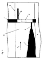
- FIG. 1 shows a schematic representation of the basic design of a reactor for implementation of the method according to the invention, consisting of the Senkschacht 1 and the reactive introduced therein Material 2, for pollutants heavier than water are and therefore in the lower part of the aquifer are located.
- the sink shaft 1 of the reactor is formed, for example, from concrete segments 2.5 m high and an inner diameter of 3 m and a shaft depth of 20 m and is founded into the impermeable horizon 6.
- the sinking shaft 1 is filled with reactive materials 2 such as Fe o and has gravel-jacketed wells 3 in the lower area, in the immediate target horizon, which are driven, for example, 10 m long into the aquifer. Because of the hydraulic properties, the contaminated groundwater 5 is guided into the shaft 1 filled with reaction materials 2 via this water catchment in the lower region of the groundwater-carrying layer 8 due to the hydraulic properties.
- groundwater supplied for decontamination flows through the reaction material 2 vertically (arrow direction) (according to dimensioning) and is then infiltrated in the upper region of the water-bearing layer 8, ie, drained below the groundwater level 9 (discharge vane 4).
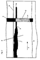
- FIG. 2 shows a schematic representation of the Training the reactor for a situation where the Pollutants are lighter than water and therefore in upper region of the water-bearing layer 8 over horizontal gravel jacket fountain 3 in the reactor be initiated.
- the contaminated water 5 is in the sink shaft 1 the reactive material 2 initially, possibly by means of a pump, not shown, on a in Floor area of the countersink 1 open partition 10 vertically down and then redirected up led and then below the water table 9 diverted (exhaust vane 4).
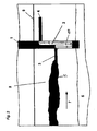
- FIG 3 shows a schematic representation of the Formation of the reactor, consisting of the sink shaft 1 with the reactive material 2 in the event that the pollutants in the middle of the water-bearing Layer 8 are located.
- the horizontal pebble-jacketed wells are from the sink shaft 1 3 directly into the target horizon with the contaminated water 5 driven, the contaminated Water 5 is fed into the sink shaft 1 and as in Example 2 through the reactive material 2 of Countersunk shaft 1 and below the water table 9 led out (exhaust vane 4).
Landscapes
- Life Sciences & Earth Sciences (AREA)
- Engineering & Computer Science (AREA)
- Hydrology & Water Resources (AREA)
- Water Supply & Treatment (AREA)
- Soil Sciences (AREA)
- Environmental & Geological Engineering (AREA)
- Treatment Of Water By Oxidation Or Reduction (AREA)
- Processing Of Solid Wastes (AREA)
- Catalysts (AREA)
- Organic Low-Molecular-Weight Compounds And Preparation Thereof (AREA)
Description
- Fig. 1
- eine schematische Darstellung des Reaktors nach der Erfindung in Arbeitsposition für Schadstoffe schwerer als Wasser,
- Fig. 2
- eine schematische Darstellung des Reaktors nach Fig. 1 für Schadstoffe leichter als Wasser und
- Fig. 3
- eine schematische Darstellung des Reaktors nach Fig. 1 für Schadstoffe im mittleren Bereich.
- 1
- Senkschacht
- 2
- Reaktives Material
- 3
- Kiesmantelbrunnen (Zuleitung,Horizontal-Drainage)
- 4
- Abstromfahne (Ableitung)
- 5
- Schadstoffahne (kontaminiertes Wasser)
- 6
- Undurchlässiger Horizont
- 7
- Grundwasser-Fließrichtung
- 8
- Grundwasserführende Schicht
- 9
- Grundwasserspiegel
- 10
- Zwischenwand
Claims (8)
- Verfahren zur Dekontamination von Grundwasser unter Verwendung von Reaktionsmittein,
wobei
das kontaminierte Grundwasser (5) unterhalb des Grundwasserspiegels (9) in einen Reaktor (1, 2) eingeleitet und durch eine Reaktionskammer (1) mit mindestens einem Reaktionsmittel (2) in Abhängigkeit von der gewünschten Aufenthaltsdauer geführt und als gereinigtes Grundwasser (4) in einer gewünschten Höhe aus dem Reaktor (1, 2) abgeleitet wird,
dadurch gekennzeichnet, dass
unter Verwendung der Senkrechtschacht-Technologie aus der Brunnen-Bohrtechnik die Herstellung von Horizontalfilterbrunnen erfolgt und die Höhe der Grundwassereinleitung in den Reaktor (1, 2) abhängig von der Schadstoffart und der Schadstofflage im Grundwasser (8) gewählt wird derart,
dass Schadstoffe, weiche leichter sind als Wasser, dem Reaktor (1, 2) im oberen Bereich unterhalb des Grundwasserspiegels (9) zugeführt werden, dass Schadstoffe, welche etwa gleich schwer sind wie Wasser und/oder welche in Wasser schweben und/oder welche durch undurchlässige Bodenbereiche an der Höhenveränderung gehindert werden, dem Reaktor im mittleren Bereich zugeführt werden und dass Schadstoffe, welche schwerer sind als Wasser, dem Reaktor (1, 2) im unteren Bereich zugeführt werden. - Verfahren nach Anspruch 1, dadurch gekennzeichnet, daß der Reaktor (1,2) vertikal bis in die Sohle des Horizontes hinein, der das kontaminierte Grundwasser (5) führt, eingebracht wird, wobei in dem für die Grundwassereinleitung vorgesehenen Bereich des Reaktors (1,2) mindestens eine perforierte Zuleitung (3) horizontal in das Grundwasser (8) herausgeführt wird, über die das kontaminierte Grundwasser (5) in den mit Reaktionsmittel (2) gefüllten Reaktor (1) einströmt.
- Verfahren nach den Ansprüchen 1 und 2, dadurch gekennzeichnet, daß zur Erfassung von Schadstoffen, die schwerer als Wasser sind, das Grundwasser dem Reaktor (1,2) im unteren Bereich zugeführt und unterhalb des Grundwasserspiegels (9) aus dem oberen Bereich des Reaktors (1,2) als gereinigtes Grundwasser (4) abgeleitet wird.
- Verfahren nach den Ansprüchen 1 und 2, dadurch gekennzeichnet, daß zur Erfassung von Schadstoffen, die leichter als Wasser sind, das Grundwasser dem Reaktor (1,2) im oberen Bereich unterhalb des Grundwasserspiegels (9) zugeführt und auch wieder abgeleitet wird, nachdem das kontaminierte Grundwasser (5) zur Erzielung einer längeren Aufenthaltsdauer im Reaktor (1,2) entlang einer Zwischenwand (10), die im unteren Bereich des Reaktors (1,2) offen ist, zunächst abwärts und danach aufwärts gerichtet geführt wurde.
- Verfahren nach Ansprüchen 1 und 2, dadurch gekennzeichnet, daß zur Erfassung von Schadstoffen, die sich im mittleren Bereich der grundwasserführenden Schicht (8) befinden, das Grundwasser dem Reaktor (1,2) im mittleren Bereich zugeführt, entlang einer Zwischenwand (10) nach unten geführt, dort entlang der Zwischenwand in den oberen Bereich des Reaktors (1,2) geleitet und unterhalb des Grundwasserspiegels (9) herausgeführt wird.
- Reaktor zur Dekontamination von Grundwasser, wobei eine Reaktionskammer (1) zur Aufnahme mindestens eines Reaktionsmittels (2)bis zur Reaktorsohle reicht und unterhalb des Grundwasserspiegels (9) verschlossen ist und die Reaktionskammer (1) mindestens eine Zu- und mindestens eine Ableitung(3,4) unterhalb des Grundwasserspiegels (9) aufweist,
dadurch gekennzeichnet, dass
der Reaktor in der Art eines Senkrechtschachtes in Kombination mit einem Horizontalfilter-Brunnen ausgebildet ist, wobei mindestens eine Zuleitung für Schadstoffe, die leichter sind als Wasser, im oberen Bereich angeordnet ist und/oder mindestens eine Zuleitung für Schadstoffe, die gleich schwer sind wie Wasser und/oder welche in Wasser schweben und/oder welche durch undurchlässige Bodenbereiche an der Höhenveränderung gehindert werden, im mittleren Bereich angeordnet ist und/oder mindestens eine Zuleitung für Schadstoffe, die schwerer sind als Wasser, im unteren Bereich angeordnet ist. - Reaktor nach Anspruch 6, dadurch gekennzeichnet, daß im Reaktor (1,2) mindestens eine nach oben oder nach unten offene Zwischenwand (10) eingebracht ist.
- Reaktor nach Anspruch 6, dadurch gekennzeichnet, daß mehrere Reaktoren (1,2) miteinander verbunden sind.
Applications Claiming Priority (3)
| Application Number | Priority Date | Filing Date | Title |
|---|---|---|---|
| DE19860129 | 1998-12-17 | ||
| DE19860129A DE19860129A1 (de) | 1998-12-17 | 1998-12-17 | Verfahren und Reaktor zur Dekontamination von Grundwasser |
| PCT/EP1999/010011 WO2000035812A2 (de) | 1998-12-17 | 1999-12-16 | Verfahren und reaktor zur dekontamination von grundwasser |
Publications (3)
| Publication Number | Publication Date |
|---|---|
| EP1144312A2 EP1144312A2 (de) | 2001-10-17 |
| EP1144312A3 EP1144312A3 (de) | 2002-11-20 |
| EP1144312B1 true EP1144312B1 (de) | 2004-10-20 |
Family
ID=7892707
Family Applications (1)
| Application Number | Title | Priority Date | Filing Date |
|---|---|---|---|
| EP99965480A Expired - Lifetime EP1144312B1 (de) | 1998-12-17 | 1999-12-16 | Verfahren und reaktor zur dekontamination von grundwasser |
Country Status (6)
| Country | Link |
|---|---|
| US (1) | US6758979B1 (de) |
| EP (1) | EP1144312B1 (de) |
| AT (1) | ATE280000T1 (de) |
| DE (2) | DE19860129A1 (de) |
| ES (1) | ES2232199T3 (de) |
| WO (1) | WO2000035812A2 (de) |
Families Citing this family (2)
| Publication number | Priority date | Publication date | Assignee | Title |
|---|---|---|---|---|
| US7374691B2 (en) * | 2005-01-19 | 2008-05-20 | T H Agriculture & Nutrition | In-situ hydraulic treatment conduit |
| US8580114B2 (en) | 2011-06-16 | 2013-11-12 | Kleinfelder West, Inc. | Processes for remediation of contaminant plumes |
Family Cites Families (18)
| Publication number | Priority date | Publication date | Assignee | Title |
|---|---|---|---|---|
| GB2094519B (en) | 1981-03-06 | 1984-09-12 | Marconi Co Ltd | Stabilised power supply |
| DE3722653A1 (de) * | 1987-07-09 | 1989-01-26 | Preussag Ag Bauwesen | Verfahren zum bau einer grundwassermessstelle und vorrichtung zur durchfuehrung des verfahrens |
| US4919568A (en) * | 1988-04-27 | 1990-04-24 | Dennis Hurley | System for draining land areas through siphoning from a permeable catch basin |
| DE4001011C1 (en) * | 1990-01-16 | 1990-12-13 | Ieg - Industrie-Engineering Gmbh, 7410 Reutlingen, De | Ground water flow control - comprises shaft sunk into ground water levels with successive permeable and impermeable wall areas |
| DE3931012C1 (de) * | 1989-09-16 | 1991-04-18 | Ieg - Industrie-Engineering Gmbh, 7410 Reutlingen, De | |
| GB8926853D0 (en) | 1989-11-28 | 1990-01-17 | Gillham Robert W | Cleaning halogenated contaminants from water |
| DE4037059A1 (de) * | 1990-11-22 | 1992-05-27 | Ieg Ind Engineering Gmbh | Anordnung zum reinigen von verschmutztem grundwasser |
| GB9104509D0 (en) | 1991-03-04 | 1991-04-17 | Blowes David W | System for treating contaminated ground water |
| GB2255087B (en) | 1991-04-25 | 1995-06-21 | Robert Winston Gillham | System for cleaning contaminated water |
| DE4227570C1 (de) * | 1992-05-29 | 1993-09-30 | Ieg Ind Engineering Gmbh | Anordnung zum Austreiben leichtflüchtiger Verunreinigungen an Ort und Stelle |
| DE4221198C2 (de) | 1992-06-27 | 1994-04-28 | Steffen Ingenieurgesellschaft | Verfahren zum Entfernen von wasserlöslichen sorbierbaren Schadstoffen aus einem abströmenden Grundwasser in der Umgebung eines Kontaminationsherdes |
| DE4407835A1 (de) * | 1994-03-09 | 1995-09-14 | Ieg Ind Engineering Gmbh | Verfahren und Vorrichtung zum Entfernen von schwerflüchtigen flüssigen Verunreinigungen geringerer Dichte als Wasser aus dem grundwasserdurchströmten Erdreich |
| DE4425061C1 (de) * | 1994-07-15 | 1995-10-26 | Wci Umwelttechnik Gmbh | Permeables Behandlungsbett zur Reinigung kontaminierter Grundwasserströme in situ |
| US5730871A (en) * | 1996-06-03 | 1998-03-24 | Camco International, Inc. | Downhole fluid separation system |
| DE19735920A1 (de) * | 1996-08-21 | 1998-03-12 | Berger Erich Dipl Geol | Brunnen zum Reinigen von Wasser, insbesondere von kontaminiertem Schadstoff belastetem Grundwasser |
| US5910245A (en) * | 1997-01-06 | 1999-06-08 | Ieg Technologies Corp. | Bioremediation well and method for bioremediation treatment of contaminated water |
| DE19715038B4 (de) * | 1997-04-11 | 2005-03-03 | Sax + Klee Gmbh | Wasserdurchlässige Filterwand und Verfahren zur Herstellung der Filterwand |
| US6224770B1 (en) * | 1999-03-19 | 2001-05-01 | Exxon Research And Engineering Company | Biowall for groundwater remediation |
-
1998
- 1998-12-17 DE DE19860129A patent/DE19860129A1/de not_active Ceased
-
1999
- 1999-12-16 AT AT99965480T patent/ATE280000T1/de not_active IP Right Cessation
- 1999-12-16 ES ES99965480T patent/ES2232199T3/es not_active Expired - Lifetime
- 1999-12-16 DE DE59910914T patent/DE59910914D1/de not_active Expired - Fee Related
- 1999-12-16 EP EP99965480A patent/EP1144312B1/de not_active Expired - Lifetime
- 1999-12-16 US US09/868,416 patent/US6758979B1/en not_active Expired - Fee Related
- 1999-12-16 WO PCT/EP1999/010011 patent/WO2000035812A2/de not_active Ceased
Also Published As
| Publication number | Publication date |
|---|---|
| EP1144312A3 (de) | 2002-11-20 |
| ES2232199T3 (es) | 2005-05-16 |
| ATE280000T1 (de) | 2004-11-15 |
| DE59910914D1 (de) | 2004-11-25 |
| EP1144312A2 (de) | 2001-10-17 |
| WO2000035812A2 (de) | 2000-06-22 |
| DE19860129A1 (de) | 2000-06-21 |
| WO2000035812A3 (de) | 2002-10-03 |
| US6758979B1 (en) | 2004-07-06 |
Similar Documents
| Publication | Publication Date | Title |
|---|---|---|
| DE3739126C2 (de) | ||
| DE69304048T2 (de) | Anordnung zur behandlung von verunreinigtem grundwasser | |
| DE69612321T2 (de) | Senkrechtes Isolationssystem für die Zweiphasenextraktion von Boden- und Grundwasserverunreinigungen | |
| DE69029314T2 (de) | Verfahren und Vorrichtung für die Zweiphasen-Vakuumextraktion von Bodenverunreinigungen | |
| DE2726012A1 (de) | Verfahren zur verhinderung der verunreinigung des grundwassers durch auf der erdoberflaeche oder in unterirdischen hohlraeumen gelagerte stoffe | |
| EP0471158B1 (de) | Anlage zur Sicherung einer Deponie gegen vagabundierendes Austreten von Sickerwasser und verfahrensmässige Massnahmen | |
| EP0335162B1 (de) | Verfahren sowie Vorrichtung zur Reinigung von Bodenschichten | |
| EP0301060A1 (de) | Vorrichtung zur erschliessung von mülldeponiegasquellen und zur erkundung und sanierung von altlasten und verunreinigten böden. | |
| DE4425061C1 (de) | Permeables Behandlungsbett zur Reinigung kontaminierter Grundwasserströme in situ | |
| DE3108331A1 (de) | "verfahren und vorrichtung fuer die herstellung von grundwasserbrunnen und fuer die grundwasserabsenkung" | |
| DE69632140T2 (de) | Methode und apparat zur unterirdischen biologischen sanierung | |
| DE19860129A1 (de) | Verfahren und Reaktor zur Dekontamination von Grundwasser | |
| DE19715038B4 (de) | Wasserdurchlässige Filterwand und Verfahren zur Herstellung der Filterwand | |
| DE3734537A1 (de) | Filterbrunnen | |
| EP3643872B1 (de) | Verfahren zur reduzierung einer hydraulisch wirksamen porosität einer porösen feststoffmatrix | |
| DE19859862B4 (de) | Verfahren und Vorrichtung zur Grundwassersanierung mittels Dichtwand-Heber-Reaktor | |
| EP1394117B1 (de) | Vorrichtung zum Dekontaminieren von Grundwasserströmen sowie Verfahren zur Herstellung einer derartigen Vorrichtung | |
| DE2318102C3 (de) | Brunnen zum Umschichten von Grundwasser aus einem Grundwasserhorizont in einen durch eine undurchlässige Sperrschicht davon getrennten zweiten Grundwasserhorizont | |
| DE19500149C2 (de) | Verfahren zur Regenerierung von Drainagerohren, sowie Anordnung zur Durchführung eines solchen Verfahrens | |
| EP1099489B1 (de) | Bauwerk zur Boden- und Grundwassersanierung und Verfahren zur Errichtung eines solchen | |
| DE3720917A1 (de) | Vorrichtung zum entgiften grosser wassermengen mit hilfe von aktivkohle | |
| DE19729303B4 (de) | Verfahren zur Reinigung Kontamienierter Grundwasserströme in situ in einem permeablen Reaktorraum | |
| DE19848695B4 (de) | Verfahren zur Reduktion von Schadstoffverschleppungen aus kontaminierten Bodenbereichen | |
| DE19846804A1 (de) | Verfahren zur nachträglichen passiven in situ-Reinigung von kontaminiertem Grundwasser | |
| DE19528330C2 (de) | Herstellung einer Baugrube mit nachträglichem Grundwasserdurchfluß |
Legal Events
| Date | Code | Title | Description |
|---|---|---|---|
| PUAI | Public reference made under article 153(3) epc to a published international application that has entered the european phase |
Free format text: ORIGINAL CODE: 0009012 |
|
| 17P | Request for examination filed |
Effective date: 20010614 |
|
| AK | Designated contracting states |
Kind code of ref document: A2 Designated state(s): AT BE CH CY DE DK ES FI FR GB GR IE IT LI LU MC NL PT SE |
|
| XX | Miscellaneous (additional remarks) |
Free format text: DERZEIT SIND DIE WIPO-PUBLIKATIONSDATEN A3 NICHT VERFUEGBAR. |
|
| PUAK | Availability of information related to the publication of the international search report |
Free format text: ORIGINAL CODE: 0009015 |
|
| AK | Designated contracting states |
Kind code of ref document: A3 Designated state(s): AT BE CH CY DE DK ES FI FR GB GR IE IT LI LU MC NL PT SE |
|
| RIC1 | Information provided on ipc code assigned before grant |
Free format text: 7B 09C 1/00 A |
|
| GRAP | Despatch of communication of intention to grant a patent |
Free format text: ORIGINAL CODE: EPIDOSNIGR1 |
|
| 17Q | First examination report despatched |
Effective date: 20031029 |
|
| GRAS | Grant fee paid |
Free format text: ORIGINAL CODE: EPIDOSNIGR3 |
|
| GRAA | (expected) grant |
Free format text: ORIGINAL CODE: 0009210 |
|
| RIN1 | Information on inventor provided before grant (corrected) |
Inventor name: TEUTSCH, GEORG Inventor name: WEISS, HOLGER |
|
| AK | Designated contracting states |
Kind code of ref document: B1 Designated state(s): AT BE CH CY DE DK ES FI FR GB GR IE IT LI LU MC NL PT SE |
|
| PG25 | Lapsed in a contracting state [announced via postgrant information from national office to epo] |
Ref country code: SE Free format text: LAPSE BECAUSE OF FAILURE TO SUBMIT A TRANSLATION OF THE DESCRIPTION OR TO PAY THE FEE WITHIN THE PRESCRIBED TIME-LIMIT Effective date: 20041020 Ref country code: NL Free format text: LAPSE BECAUSE OF FAILURE TO SUBMIT A TRANSLATION OF THE DESCRIPTION OR TO PAY THE FEE WITHIN THE PRESCRIBED TIME-LIMIT Effective date: 20041020 Ref country code: IE Free format text: LAPSE BECAUSE OF FAILURE TO SUBMIT A TRANSLATION OF THE DESCRIPTION OR TO PAY THE FEE WITHIN THE PRESCRIBED TIME-LIMIT Effective date: 20041020 Ref country code: FR Free format text: LAPSE BECAUSE OF FAILURE TO SUBMIT A TRANSLATION OF THE DESCRIPTION OR TO PAY THE FEE WITHIN THE PRESCRIBED TIME-LIMIT Effective date: 20041020 Ref country code: FI Free format text: LAPSE BECAUSE OF FAILURE TO SUBMIT A TRANSLATION OF THE DESCRIPTION OR TO PAY THE FEE WITHIN THE PRESCRIBED TIME-LIMIT Effective date: 20041020 Ref country code: CY Free format text: LAPSE BECAUSE OF FAILURE TO SUBMIT A TRANSLATION OF THE DESCRIPTION OR TO PAY THE FEE WITHIN THE PRESCRIBED TIME-LIMIT Effective date: 20041020 |
|
| REG | Reference to a national code |
Ref country code: GB Ref legal event code: FG4D Free format text: NOT ENGLISH |
|
| XX | Miscellaneous (additional remarks) |
Free format text: DERZEIT SIND DIE WIPO-PUBLIKATIONSDATEN A3 NICHT VERFUEGBAR. |
|
| REG | Reference to a national code |
Ref country code: CH Ref legal event code: EP |
|
| REG | Reference to a national code |
Ref country code: IE Ref legal event code: FG4D Free format text: GERMAN |
|
| REF | Corresponds to: |
Ref document number: 59910914 Country of ref document: DE Date of ref document: 20041125 Kind code of ref document: P |
|
| PG25 | Lapsed in a contracting state [announced via postgrant information from national office to epo] |
Ref country code: LU Free format text: LAPSE BECAUSE OF NON-PAYMENT OF DUE FEES Effective date: 20041216 Ref country code: AT Free format text: LAPSE BECAUSE OF NON-PAYMENT OF DUE FEES Effective date: 20041216 |
|
| PG25 | Lapsed in a contracting state [announced via postgrant information from national office to epo] |
Ref country code: MC Free format text: LAPSE BECAUSE OF NON-PAYMENT OF DUE FEES Effective date: 20041231 Ref country code: LI Free format text: LAPSE BECAUSE OF NON-PAYMENT OF DUE FEES Effective date: 20041231 Ref country code: CH Free format text: LAPSE BECAUSE OF NON-PAYMENT OF DUE FEES Effective date: 20041231 Ref country code: BE Free format text: LAPSE BECAUSE OF NON-PAYMENT OF DUE FEES Effective date: 20041231 |
|
| PG25 | Lapsed in a contracting state [announced via postgrant information from national office to epo] |
Ref country code: GR Free format text: LAPSE BECAUSE OF FAILURE TO SUBMIT A TRANSLATION OF THE DESCRIPTION OR TO PAY THE FEE WITHIN THE PRESCRIBED TIME-LIMIT Effective date: 20050120 Ref country code: DK Free format text: LAPSE BECAUSE OF FAILURE TO SUBMIT A TRANSLATION OF THE DESCRIPTION OR TO PAY THE FEE WITHIN THE PRESCRIBED TIME-LIMIT Effective date: 20050120 |
|
| GBT | Gb: translation of ep patent filed (gb section 77(6)(a)/1977) |
Effective date: 20050214 |
|
| NLV1 | Nl: lapsed or annulled due to failure to fulfill the requirements of art. 29p and 29m of the patents act | ||
| REG | Reference to a national code |
Ref country code: ES Ref legal event code: FG2A Ref document number: 2232199 Country of ref document: ES Kind code of ref document: T3 |
|
| REG | Reference to a national code |
Ref country code: IE Ref legal event code: FD4D |
|
| BERE | Be: lapsed |
Owner name: UFZ-UMWELTFORSCHUNGSZENTRUM LEIPZIG-HALLE G.M.B.H. Effective date: 20041231 |
|
| REG | Reference to a national code |
Ref country code: CH Ref legal event code: PL |
|
| PLBE | No opposition filed within time limit |
Free format text: ORIGINAL CODE: 0009261 |
|
| STAA | Information on the status of an ep patent application or granted ep patent |
Free format text: STATUS: NO OPPOSITION FILED WITHIN TIME LIMIT |
|
| 26N | No opposition filed |
Effective date: 20050721 |
|
| EN | Fr: translation not filed | ||
| PGFP | Annual fee paid to national office [announced via postgrant information from national office to epo] |
Ref country code: GB Payment date: 20061218 Year of fee payment: 8 |
|
| PGFP | Annual fee paid to national office [announced via postgrant information from national office to epo] |
Ref country code: ES Payment date: 20061220 Year of fee payment: 8 |
|
| PGFP | Annual fee paid to national office [announced via postgrant information from national office to epo] |
Ref country code: IT Payment date: 20061231 Year of fee payment: 8 |
|
| PGFP | Annual fee paid to national office [announced via postgrant information from national office to epo] |
Ref country code: DE Payment date: 20070123 Year of fee payment: 8 |
|
| BERE | Be: lapsed |
Owner name: UMWELTFORSCHUNGSZENTRUM LEIPZIG-HALLE G.M.B.H. *UF Effective date: 20041231 |
|
| PG25 | Lapsed in a contracting state [announced via postgrant information from national office to epo] |
Ref country code: PT Free format text: LAPSE BECAUSE OF NON-PAYMENT OF DUE FEES Effective date: 20050320 |
|
| GBPC | Gb: european patent ceased through non-payment of renewal fee |
Effective date: 20071216 |
|
| PG25 | Lapsed in a contracting state [announced via postgrant information from national office to epo] |
Ref country code: DE Free format text: LAPSE BECAUSE OF NON-PAYMENT OF DUE FEES Effective date: 20080701 |
|
| PG25 | Lapsed in a contracting state [announced via postgrant information from national office to epo] |
Ref country code: GB Free format text: LAPSE BECAUSE OF NON-PAYMENT OF DUE FEES Effective date: 20071216 |
|
| REG | Reference to a national code |
Ref country code: ES Ref legal event code: FD2A Effective date: 20071217 |
|
| PG25 | Lapsed in a contracting state [announced via postgrant information from national office to epo] |
Ref country code: ES Free format text: LAPSE BECAUSE OF NON-PAYMENT OF DUE FEES Effective date: 20071217 |
|
| PG25 | Lapsed in a contracting state [announced via postgrant information from national office to epo] |
Ref country code: IT Free format text: LAPSE BECAUSE OF NON-PAYMENT OF DUE FEES Effective date: 20071216 |