EP1143321A2 - Handschaltung für ein Kraftfahrzeug - Google Patents
Handschaltung für ein Kraftfahrzeug Download PDFInfo
- Publication number
- EP1143321A2 EP1143321A2 EP01106621A EP01106621A EP1143321A2 EP 1143321 A2 EP1143321 A2 EP 1143321A2 EP 01106621 A EP01106621 A EP 01106621A EP 01106621 A EP01106621 A EP 01106621A EP 1143321 A2 EP1143321 A2 EP 1143321A2
- Authority
- EP
- European Patent Office
- Prior art keywords
- control handle
- locking
- manual
- sleeve
- handle
- Prior art date
- Legal status (The legal status is an assumption and is not a legal conclusion. Google has not performed a legal analysis and makes no representation as to the accuracy of the status listed.)
- Granted
Links
Images


Classifications
-
- G—PHYSICS
- G05—CONTROLLING; REGULATING
- G05G—CONTROL DEVICES OR SYSTEMS INSOFAR AS CHARACTERISED BY MECHANICAL FEATURES ONLY
- G05G1/00—Controlling members, e.g. knobs or handles; Assemblies or arrangements thereof; Indicating position of controlling members
- G05G1/04—Controlling members for hand actuation by pivoting movement, e.g. levers
- G05G1/06—Details of their grip parts
-
- F—MECHANICAL ENGINEERING; LIGHTING; HEATING; WEAPONS; BLASTING
- F16—ENGINEERING ELEMENTS AND UNITS; GENERAL MEASURES FOR PRODUCING AND MAINTAINING EFFECTIVE FUNCTIONING OF MACHINES OR INSTALLATIONS; THERMAL INSULATION IN GENERAL
- F16H—GEARING
- F16H59/00—Control inputs to control units of change-speed- or reversing-gearings for conveying rotary motion
- F16H59/02—Selector apparatus
- F16H59/0278—Constructional features of the selector lever, e.g. grip parts, mounting or manufacturing
Definitions
- the invention relates to a manual transmission for a motor vehicle according to the genus Main claim.
- Such a manual switch is known for example from DE 197 50 031 A1.
- a securing sleeve is an actuating sleeve and a helical spring guided therein, which fixes the locking sleeve in the desired holds the locking tabs of a control handle encompassing position positioning.
- This structure of a manual shift lever requires many additional components and claims one Space that is not available in many manual circuit arrangements.
- a spacer ring must be removed to remove the control handle and the Actuation sleeve are moved before the locking sleeve against the Coil spring force can be removed from the mounting section.
- the invention is based on the object, a generic To improve manual transmission for a motor vehicle so that a simple, out of a few Components existing secure attachment of the control handle on the hand lever is guaranteed, which can also be easily assembled and disassembled and only has a small installation depth.
- the locking sleeve is pre-assembled on the control handle before the control handle on the Manual shift lever is inserted. Are the locking elements of the control handle not in the Moving the locking sleeve is also engaged in the ring groove of the manual control lever not possible in their end position. This gives the fitter feedback that the Shift handle has not yet been positioned correctly. This will result in incorrect assembly avoided.
- the annular shoulder designed as a stop on a wall section of the control handle has a chamfer with an angle between 45 ° and 60 °.
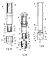
- the shift knob or shift handle shown for mounting on a manual shift lever 8 10 consists of a head part 12, which later with a plastic to form a Switch button is foamed.
- the core piece 14 adjoining the head part 12 has a beveled ring shoulder 16 at its lower end.
- the Function of the annular shoulder 16, which in the present exemplary embodiment has a chamfer of 45 ° is provided, will be described in more detail later when installing the control handle.
- On the centerpiece 14 or the ring shoulder 16 is closed in diameter compared to the core 14 reduced wall section 18, the four over his Has circumferentially distributed locking elements 20, hereinafter referred to as locking tongues.
- the radially deflectable locking tongues 20 have an inward at their lower end directed annular bead 22, which, as explained in more detail later, in an annular groove 23 of the Engage the hand control lever 8. At the end of the locking tongues 20 follows the Ring bead 22 on a stop 24, which is directed outwards with a chamfer of 90 ° provided ring element is formed.
- locking sleeve 28 consists of a closed Ring section 30, the radial in the circumferential direction of the securing sleeve 28 in four deflectable locking tongues 32 passes.
- the locking tongues 32 have on their Ring section 30 opposite end locking lugs 34, each with two under 45 ° extending flanks 36, 38 are provided.
- the closed ring section 30 has a chamfer of 45 ° and as Stop trained inner shoulder 40. Are on the end face of the ring portion 30 Guide lugs 42 formed in the assembled state as an anti-rotation lock engage gaps 44 formed between the locking tongues 20. On the outer circumference of the Ring section 30 are further flanged two guide shoulders 46, the serve better handling or assembly of the securing sleeve 28.
- the assembly of the control handle 10 on the manual shift lever 8 is carried out in the following manner and Way:
- the securing sleeve 28 is first on the control handle 10 advanced, as shown in Fig. 2c, the inner shoulder 40 of the closed Ring section 30 is pushed to the annular shoulder 16 of the core piece 14. Because the locking tongues 20 can be deflected radially, the ring section 30 can slight bending of the locking tongues 20 can be pushed inwards on these; through the also radially deflectable locking tongues 32 is the sliding of the locking tongues 32 on the core 14 possible.
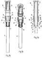
- the pre-assembled unit is opened as a second assembly step pushed the manual shift lever 8 until the ring beads 22 of the locking tongues 20 in engage the annular groove 23 of the manual shift lever 8.
- the last assembly step is, as in 4, the securing sleeve 28 with its closed ring section 30 in Moved towards the locking tongues 20 until the end face of the closed Ring section 30 on the ring element 24 designed as a stop to bear is coming.
- the dimensions of the control handle 10 and the locking sleeve 28 are so coordinated that at the same time in this position, the upper edge 36 of the locking lugs 34 the ring shoulder 16 comes to rest. In this state, the annular bead 22 is through the closed ring section 30 of the securing sleeve 28 is held in the annular groove 23, so that the shift handle 10 on the manual shift lever 8 in the intended axial position is locked against rotation.
- Disassembly of the control handle 10 from the manual shift lever 8 is simple and This is possible in that the securing sleeve 28 in the direction of the head part 12 of the Switch handle 10 overcoming the trained on the annular shoulder 16 Is pulled.
- the closed ring section 30 gives the ring bead 22 the locking tongues 20 free, so that the shift handle 10 is pulled from the manual shift lever 8 can be.
- Fig. 5 is an incorrect motor position of the shift handle on the manual shift lever shown, in which the locking tongues 20 of the control handle 10 is not in the annular groove 23rd are included.
- the further assembly i.e. moving the locking sleeve 28 in their end position is not possible.
- the fitter gets the feedback that the shift handle 10 is not yet correctly seated on the manual shift lever 8
Landscapes
- Engineering & Computer Science (AREA)
- General Engineering & Computer Science (AREA)
- Physics & Mathematics (AREA)
- General Physics & Mathematics (AREA)
- Automation & Control Theory (AREA)
- Mechanical Engineering (AREA)
- Arrangement Or Mounting Of Control Devices For Change-Speed Gearing (AREA)
- Gear-Shifting Mechanisms (AREA)
- Mechanical Control Devices (AREA)
Abstract
Description
- Fig. 1a
- eine Seitenansicht,
- Fig. 1b
- eine perspektivische Ansicht und
- Fig. 1c
- einen Längsschnitt durch einen Schaltgriff mit Sicherungshülse,
- Fig. 2a
- eine Seitenansicht,
- Fig. 2b
- eine perspektivische Ansicht und
- Fig. 2c
- einen Längsschnitt durch den Schaltgriff mit Sicherungshülse im vormontierten Zustand,
- Fig. 3a
- eine Seitenansicht,
- Fig. 3b
- eine perspektivische Ansicht und
- Fig. 3c
- einen Längsschnitt durch den Schaltgriff mit Sicherungshülse im vormontierten Zustand auf dem Handschalthebel,
- Fig. 4a
- eine Seitenansicht,
- Fig. 4b
- eine perspektivische Ansicht und
- Fig. 4c
- einen Längsschnitt durch den Schaltgriff mit Sicherungshülse auf dem Handschalthebel im montierten Endzustand und
- Fig. 5
- eine Darstellung des Schaltgriffs in einer nicht korrekten Montagestellung auf dem Handschalthebel.
Claims (6)
- Handschaltung für ein Kraftfahrzeug, mit einem Handschalthebel, der an seinem einen Ende ein Schaltgriff aufweist, und an seinem anderen Ende mit funktionell nachgeordneten Schaltelementen verbunden ist, wobei der Schaltgriff im Montagezustand gegenüber dem Handschalthebel axial unverschiebbar festgelegt ist, indem radial auslenkbare Rastelemente des Schaltgriffs in eine Ringnut des Handschalthebels eingreifen und im Montagezustand in der Ringnut durch ein die Rastelemente umgreifendes Sicherungselement gehalten sind, dadurch gekennzeichnet, daß eine Sicherungshülse (28) radial auslenkbare Rastzungen (20) und einen Ringabschnitt (30) aufweist, wobei der Ringabschnitt (30) im montierten Zustand des Schaltgriffs (10) die Rastelemente (20) des Schaltgriffs (10) umgreift, während die Rastzungen (32) der Sicherungshülse (28) an einem Wandungsabschnitt (18) des Schaltgriffs (10) abgestützt sind.
- Handschaltung nach Anspruch 1, dadurch gekennzeichnet, daß für eine Vormontage der Sicherungshülse (28) auf dem Schaltgriff (10) der Ringabschnitt (30) der Sicherungshülse (28) innen einen Gegenanschlag (40) aufweist.
- Handschaltung nach Anspruch 1 oder 2, dadurch gekennzeichnet, daß die Rastzungen (20) des Schaltgriffs (10) einen Außenanschlag (24) aufweisen, an dem im montierten Zustand des Schaltgriffs (10) der Ringabschnitt (30) der Sicherungshülse (28) anliegt.
- Handschaltung nach Anspruch 1, dadurch gekennzeichnet, daß der Anschlag (16) als Ringschulter mit einer Fase von 45° bis 60° ausgebildet ist.
- Handschaltung nach einem der vorhergehenden Ansprüche, dadurch gekennzeichnet, daß als Verdrehsicherung am Ringabschnitt (30) der Sicherungshülse (28) Führungsnasen (42) ausgebildet sind, die im montierten Zustand in zwischen den Rastelementen (20) des Schaltgriffs (10) ausgebildete Lücken (44) eingreifen.
- Handschaltung nach einem der vorhergehenden Ansprüche, dadurch gekennzeichnet, daß zur Montage der Sicherungshülse (28) am Außenumfang des Ringabschnittes (30) Führungsschultern (46) vorgesehen sind.
Applications Claiming Priority (2)
| Application Number | Priority Date | Filing Date | Title |
|---|---|---|---|
| DE10017247 | 2000-04-06 | ||
| DE10017247A DE10017247C1 (de) | 2000-04-06 | 2000-04-06 | Handschaltung für ein Kraftfahrzeug |
Publications (3)
| Publication Number | Publication Date |
|---|---|
| EP1143321A2 true EP1143321A2 (de) | 2001-10-10 |
| EP1143321A3 EP1143321A3 (de) | 2002-11-20 |
| EP1143321B1 EP1143321B1 (de) | 2007-09-26 |
Family
ID=7637868
Family Applications (1)
| Application Number | Title | Priority Date | Filing Date |
|---|---|---|---|
| EP01106621A Expired - Lifetime EP1143321B1 (de) | 2000-04-06 | 2001-03-16 | Handschaltung für ein Kraftfahrzeug |
Country Status (3)
| Country | Link |
|---|---|
| EP (1) | EP1143321B1 (de) |
| AT (1) | ATE374393T1 (de) |
| DE (2) | DE10017247C1 (de) |
Cited By (6)
| Publication number | Priority date | Publication date | Assignee | Title |
|---|---|---|---|---|
| EP1229271A3 (de) * | 2001-02-03 | 2005-03-02 | Dura Automotive Systems Einbeck GmbH | Handschalthebel |
| DE102004053576B3 (de) * | 2004-11-05 | 2006-04-13 | Lisa Dräxlmaier GmbH | Schaltknauf und Schalthebel mit einem solchen Schaltknauf |
| DE102007029049B4 (de) * | 2006-07-04 | 2009-07-23 | Eissmann Automotive Deutschland Gmbh | Griff einer Schaltstange |
| FR3005131A1 (fr) * | 2013-04-30 | 2014-10-31 | Peugeot Citroen Automobiles Sa | Pommeau pour tige d'un levier de vitesse disposant d'un moyen de verrouillage et/ou deverrouillage |
| EP2733392A3 (de) * | 2012-11-16 | 2015-07-08 | Delta Kogyo Co., Ltd. | Schaltknaufinstallationsstruktur |
| US20150362064A1 (en) * | 2014-06-11 | 2015-12-17 | Toyota Jidosha Kabushiki Kaisha | Shift Knob Structure |
Families Citing this family (3)
| Publication number | Priority date | Publication date | Assignee | Title |
|---|---|---|---|---|
| DE10159642B4 (de) * | 2001-12-05 | 2008-01-10 | Bayerische Motoren Werke Ag | Schaltknauf |
| DE10232801B4 (de) * | 2002-07-19 | 2005-08-25 | Eissmann Gmbh | Einrichtung zur Verbindung eines Schaltknaufs mit einem Schalt-/Wählhebel eines Kraftfahrzeuggetriebes |
| DE102012001718A1 (de) * | 2012-01-31 | 2013-08-01 | Gm Global Technology Operations, Llc | Gangschalthebel eines Fahrzeugs mit einem Bedienelement und Verfahren zur Herstellung, Montage und Demontage des Bedienelements |
Family Cites Families (5)
| Publication number | Priority date | Publication date | Assignee | Title |
|---|---|---|---|---|
| DE1202071B (de) * | 1956-01-23 | 1965-09-30 | Carr Fastener Co Ltd | Zweiteiliger Griff aus elastischem Kunststoff |
| GB2156261A (en) * | 1984-03-23 | 1985-10-09 | Wearwell Moulding Company Limi | Handle for attachment to a shank |
| JP3662631B2 (ja) * | 1995-06-23 | 2005-06-22 | 株式会社東海理化電機製作所 | シフトレバーノブの取り付け構造 |
| DE29715582U1 (de) * | 1997-09-02 | 1997-11-27 | Jordan Spritzgußtechnik GmbH, 58636 Iserlohn | Schaltknauf zur Befestigung auf dem freien Ende eines Getriebe-Schalthebels für Kraftfahrzeuge |
| DE19750031B4 (de) * | 1997-11-12 | 2005-03-03 | Dura Automotive Systems Einbeck Gmbh | Handschalthebel für ein Kraftfahrzeug |
-
2000
- 2000-04-06 DE DE10017247A patent/DE10017247C1/de not_active Expired - Fee Related
-
2001
- 2001-03-16 EP EP01106621A patent/EP1143321B1/de not_active Expired - Lifetime
- 2001-03-16 AT AT01106621T patent/ATE374393T1/de active
- 2001-03-16 DE DE50113048T patent/DE50113048D1/de not_active Expired - Lifetime
Non-Patent Citations (1)
| Title |
|---|
| None |
Cited By (8)
| Publication number | Priority date | Publication date | Assignee | Title |
|---|---|---|---|---|
| EP1229271A3 (de) * | 2001-02-03 | 2005-03-02 | Dura Automotive Systems Einbeck GmbH | Handschalthebel |
| DE102004053576B3 (de) * | 2004-11-05 | 2006-04-13 | Lisa Dräxlmaier GmbH | Schaltknauf und Schalthebel mit einem solchen Schaltknauf |
| DE102007029049B4 (de) * | 2006-07-04 | 2009-07-23 | Eissmann Automotive Deutschland Gmbh | Griff einer Schaltstange |
| EP2733392A3 (de) * | 2012-11-16 | 2015-07-08 | Delta Kogyo Co., Ltd. | Schaltknaufinstallationsstruktur |
| US9285823B2 (en) | 2012-11-16 | 2016-03-15 | Delta Kogyo Co., Ltd. | Shifting structure |
| FR3005131A1 (fr) * | 2013-04-30 | 2014-10-31 | Peugeot Citroen Automobiles Sa | Pommeau pour tige d'un levier de vitesse disposant d'un moyen de verrouillage et/ou deverrouillage |
| US20150362064A1 (en) * | 2014-06-11 | 2015-12-17 | Toyota Jidosha Kabushiki Kaisha | Shift Knob Structure |
| US9441728B2 (en) * | 2014-06-11 | 2016-09-13 | Toyota Jidosha Kabushiki Kaisha | Shift knob structure |
Also Published As
| Publication number | Publication date |
|---|---|
| ATE374393T1 (de) | 2007-10-15 |
| DE50113048D1 (de) | 2007-11-08 |
| EP1143321B1 (de) | 2007-09-26 |
| DE10017247C1 (de) | 2001-10-18 |
| EP1143321A3 (de) | 2002-11-20 |
Similar Documents
| Publication | Publication Date | Title |
|---|---|---|
| EP3345670B1 (de) | Filtereinrichtung | |
| EP2739519B1 (de) | Lenkungsanordnung | |
| EP2012036A2 (de) | Arretierung | |
| DE202008010262U1 (de) | Verbindungsbaugruppe zur Befestigung eines Anbauelements auf einem Trägerelement | |
| EP0328759A1 (de) | Anordnung zur Befestigung eines Bremskraftverstärkers | |
| DE10360612A1 (de) | Verbindung für Rohrleitungen | |
| DE10017247C1 (de) | Handschaltung für ein Kraftfahrzeug | |
| EP0186840B1 (de) | Lagergehäuse für Kraftfahrzeug-Gangschalthebel mit Rückwärtsgangsperre | |
| EP2019765A1 (de) | Vorrichtung und verfahren zur befestigung eines wischermotors an ein wischergestänge | |
| DE3401409C2 (de) | Montageanordnung für einen Kupplungsausrücker und mechanische Kupplung mit einem Koppelteil für eine solche Montageanordnung | |
| EP3850261B1 (de) | Vorrichtung zum verbinden zweier röhrenförmiger objekte | |
| DE3444855C1 (de) | Auch bei unter Druck stehendem Stecker kuppelbare Rohrabreisskupplung fuer insbes. Hydraulikleitungen | |
| EP0307971B1 (de) | Kupplungsmuffe zum Verbinden von zwei Rohrleitungsenden | |
| DE19846988B4 (de) | Betätigungsvorrichtung für eine Reibungskupplung | |
| DE3414834A1 (de) | Gezogene kraftfahrzeug-reibungskupplung mit loesbarer schnappverbindung | |
| DE102017107762A1 (de) | Lenkrad für ein kraftfahrzeug | |
| DE102005040485B4 (de) | Schalteinrichtung für ein Schaltgetriebe und Verfahren zur Herstellung einer derartigen Schalteinrichtung | |
| DE102019127345A1 (de) | Einstellvorrichtung für einen Scheinwerfer | |
| DE19750031B4 (de) | Handschalthebel für ein Kraftfahrzeug | |
| EP4062016B1 (de) | Kraftfahrzeug-schloss | |
| DE102010019029B4 (de) | Betätigungsvorrichtung für eine Kraftfahrzeugsitzverstellung | |
| DE4040955C1 (en) | Gear shift lever for motor vehicle gearbox - has surrounding sleeve sealing mounting opening in floor fixed in position by two sheaths | |
| DE69504909T2 (de) | Anschlussteil für Betätigungskabel | |
| DE69320266T2 (de) | Kabelhüllenendstück für Kraftfahrzeug | |
| DE102019107888A1 (de) | Halteanordnung eines ersten Bauteils an einem zweiten Bauteil eines Kraftfahrzeugs sowie Verfahren zum Herstellen einer Halteanordnung |
Legal Events
| Date | Code | Title | Description |
|---|---|---|---|
| PUAI | Public reference made under article 153(3) epc to a published international application that has entered the european phase |
Free format text: ORIGINAL CODE: 0009012 |
|
| AK | Designated contracting states |
Kind code of ref document: A2 Designated state(s): AT BE CH CY DE DK ES FI FR GB GR IE IT LI LU MC NL PT SE TR |
|
| AX | Request for extension of the european patent |
Free format text: AL;LT;LV;MK;RO;SI |
|
| PUAL | Search report despatched |
Free format text: ORIGINAL CODE: 0009013 |
|
| AK | Designated contracting states |
Kind code of ref document: A3 Designated state(s): AT BE CH CY DE DK ES FI FR GB GR IE IT LI LU MC NL PT SE TR |
|
| AX | Request for extension of the european patent |
Free format text: AL;LT;LV;MK;RO;SI |
|
| RIC1 | Information provided on ipc code assigned before grant |
Free format text: 7G 05G 1/06 A, 7F 16H 59/02 B, 7G 05G 1/12 B |
|
| 17P | Request for examination filed |
Effective date: 20030520 |
|
| AKX | Designation fees paid |
Designated state(s): AT DE FR GB IT |
|
| GRAP | Despatch of communication of intention to grant a patent |
Free format text: ORIGINAL CODE: EPIDOSNIGR1 |
|
| GRAS | Grant fee paid |
Free format text: ORIGINAL CODE: EPIDOSNIGR3 |
|
| GRAA | (expected) grant |
Free format text: ORIGINAL CODE: 0009210 |
|
| AK | Designated contracting states |
Kind code of ref document: B1 Designated state(s): AT DE FR GB IT |
|
| REG | Reference to a national code |
Ref country code: GB Ref legal event code: FG4D Free format text: NOT ENGLISH |
|
| REF | Corresponds to: |
Ref document number: 50113048 Country of ref document: DE Date of ref document: 20071108 Kind code of ref document: P |
|
| ET | Fr: translation filed | ||
| GBT | Gb: translation of ep patent filed (gb section 77(6)(a)/1977) |
Effective date: 20080110 |
|
| PLBE | No opposition filed within time limit |
Free format text: ORIGINAL CODE: 0009261 |
|
| STAA | Information on the status of an ep patent application or granted ep patent |
Free format text: STATUS: NO OPPOSITION FILED WITHIN TIME LIMIT |
|
| 26N | No opposition filed |
Effective date: 20080627 |
|
| REG | Reference to a national code |
Ref country code: FR Ref legal event code: TP |
|
| REG | Reference to a national code |
Ref country code: FR Ref legal event code: CD |
|
| PGFP | Annual fee paid to national office [announced via postgrant information from national office to epo] |
Ref country code: GB Payment date: 20100322 Year of fee payment: 10 |
|
| PGFP | Annual fee paid to national office [announced via postgrant information from national office to epo] |
Ref country code: IT Payment date: 20100327 Year of fee payment: 10 |
|
| REG | Reference to a national code |
Ref country code: FR Ref legal event code: TP |
|
| REG | Reference to a national code |
Ref country code: GB Ref legal event code: 732E Free format text: REGISTERED BETWEEN 20110310 AND 20110316 |
|
| REG | Reference to a national code |
Ref country code: GB Ref legal event code: 732E Free format text: REGISTERED BETWEEN 20110331 AND 20110406 |
|
| GBPC | Gb: european patent ceased through non-payment of renewal fee |
Effective date: 20110316 |
|
| PG25 | Lapsed in a contracting state [announced via postgrant information from national office to epo] |
Ref country code: GB Free format text: LAPSE BECAUSE OF NON-PAYMENT OF DUE FEES Effective date: 20110316 Ref country code: IT Free format text: LAPSE BECAUSE OF NON-PAYMENT OF DUE FEES Effective date: 20110316 |
|
| PGFP | Annual fee paid to national office [announced via postgrant information from national office to epo] |
Ref country code: DE Payment date: 20140304 Year of fee payment: 14 |
|
| PGFP | Annual fee paid to national office [announced via postgrant information from national office to epo] |
Ref country code: FR Payment date: 20140319 Year of fee payment: 14 Ref country code: AT Payment date: 20140312 Year of fee payment: 14 |
|
| REG | Reference to a national code |
Ref country code: DE Ref legal event code: R119 Ref document number: 50113048 Country of ref document: DE |
|
| REG | Reference to a national code |
Ref country code: AT Ref legal event code: MM01 Ref document number: 374393 Country of ref document: AT Kind code of ref document: T Effective date: 20150316 |
|
| REG | Reference to a national code |
Ref country code: FR Ref legal event code: ST Effective date: 20151130 |
|
| PG25 | Lapsed in a contracting state [announced via postgrant information from national office to epo] |
Ref country code: DE Free format text: LAPSE BECAUSE OF NON-PAYMENT OF DUE FEES Effective date: 20151001 |
|
| PG25 | Lapsed in a contracting state [announced via postgrant information from national office to epo] |
Ref country code: FR Free format text: LAPSE BECAUSE OF NON-PAYMENT OF DUE FEES Effective date: 20150331 Ref country code: AT Free format text: LAPSE BECAUSE OF NON-PAYMENT OF DUE FEES Effective date: 20150316 |