EP1143127A1 - Moteur à combustion interne, à rapport volumétrique et à cylindrée variables - Google Patents
Moteur à combustion interne, à rapport volumétrique et à cylindrée variables Download PDFInfo
- Publication number
- EP1143127A1 EP1143127A1 EP01400802A EP01400802A EP1143127A1 EP 1143127 A1 EP1143127 A1 EP 1143127A1 EP 01400802 A EP01400802 A EP 01400802A EP 01400802 A EP01400802 A EP 01400802A EP 1143127 A1 EP1143127 A1 EP 1143127A1
- Authority
- EP
- European Patent Office
- Prior art keywords
- piston
- connecting rod
- dead center
- axis
- rod
- Prior art date
- Legal status (The legal status is an assumption and is not a legal conclusion. Google has not performed a legal analysis and makes no representation as to the accuracy of the status listed.)
- Granted
Links
- 238000002485 combustion reaction Methods 0.000 title claims description 9
- 230000006835 compression Effects 0.000 title description 5
- 238000007906 compression Methods 0.000 title description 5
- 238000006073 displacement reaction Methods 0.000 description 18
- 230000000694 effects Effects 0.000 description 4
- 238000004513 sizing Methods 0.000 description 4
- 230000007935 neutral effect Effects 0.000 description 3
- 238000005516 engineering process Methods 0.000 description 2
- 239000000446 fuel Substances 0.000 description 2
- 239000000203 mixture Substances 0.000 description 2
- 230000004048 modification Effects 0.000 description 2
- 238000012986 modification Methods 0.000 description 2
- 240000008042 Zea mays Species 0.000 description 1
- 238000013459 approach Methods 0.000 description 1
- 230000003416 augmentation Effects 0.000 description 1
- 238000006243 chemical reaction Methods 0.000 description 1
- 230000001276 controlling effect Effects 0.000 description 1
- 230000010363 phase shift Effects 0.000 description 1
- 230000001105 regulatory effect Effects 0.000 description 1
Images



Classifications
-
- F—MECHANICAL ENGINEERING; LIGHTING; HEATING; WEAPONS; BLASTING
- F02—COMBUSTION ENGINES; HOT-GAS OR COMBUSTION-PRODUCT ENGINE PLANTS
- F02D—CONTROLLING COMBUSTION ENGINES
- F02D15/00—Varying compression ratio
- F02D15/02—Varying compression ratio by alteration or displacement of piston stroke
-
- F—MECHANICAL ENGINEERING; LIGHTING; HEATING; WEAPONS; BLASTING
- F02—COMBUSTION ENGINES; HOT-GAS OR COMBUSTION-PRODUCT ENGINE PLANTS
- F02B—INTERNAL-COMBUSTION PISTON ENGINES; COMBUSTION ENGINES IN GENERAL
- F02B75/00—Other engines
- F02B75/04—Engines with variable distances between pistons at top dead-centre positions and cylinder heads
- F02B75/048—Engines with variable distances between pistons at top dead-centre positions and cylinder heads by means of a variable crank stroke length
Definitions
- the present invention relates to an internal combustion engine.
- volumetric ratio of an engine being defined as the ratio between the volumes of the combustion chamber of a cylinder in neutral low and top dead center, the choice of volumetric ratio is a compromise between low speed and low load efficiency (low power required) and the occurrence of rattling in busier operating conditions.
- the invention aims to provide a device for adjusting the volumetric ratio and therefore to vary the displacement in depending on the conditions of use in higher proportions than what has been achieved so far and a correspondingly greater reduction in fuel consumption.
- the internal combustion engine includes means for varying the position of the top dead center between predetermined limits, in order to simultaneously vary the stroke of the piston, the position of the bottom dead center and, correspondingly, the volumetric ratio and the displacement, depending on the conditions of use of the engine.
- said means include a slave connecting rod articulated on the one hand on the piston and on the other hand on a master rod which turns on a crankshaft and said master rod is also articulated on a rod forming a pendulum, associated with a member for adjusting the position of said slave link controlling the top and bottom dead center positions.
- the schematic device shown in Figure 1 includes a cylinder 1 in which a piston 2 can execute strokes between a point top dead and bottom dead center.
- the piston 2 is linked to a rod 3 called a rod slave, articulated on the one hand on the piston 2 and on the other hand on a connecting rod main 4 which turns on a crankshaft 5.
- the main connecting rod 4 is also articulated by an axis 6 on a link 7 forming a pendulum, associated with a member 8 for adjusting the position of said rod 7.
- the balance rod is therefore articulated at 9 on the adjusting member 8 which can be for example an eccentric, a piston, a camshaft, etc ...
- the main connecting rod 4 has a short arm 11 and a long arm 12 integral with a tubular body 13 which can rotate on a crank pin 14 making integral part of a crankshaft 15.
- the latter comprises a journal 16, a arm not shown and the pin 14.
- the short arm 11 provides the connection between the crank pin 14 and the axis 17 of the link 3, while the long arm 12 provides the link between the crank pin 14 and the axis 6 of articulation on the balance rod 7.
- This device is implemented in the following manner.
- the piston 2 is represented in a bottom dead center, the cylinder 1 and the piston 2 volume ratio control device being housed in a cylinder head block 10.
- the adjusting member 8 cooperates with a actuator 20 also arranged inside the cylinder head block 10.
- each position of the adjusting member 8, controlled by a actuator 20, corresponds to a position of the balance rod 7, of the rod main or main rod 4, of the crankshaft 15 and of its journal 16, of the slave link 3 and piston 2.
- Figures 5 and 6 illustrate the extreme positions of the piston 2 for a high compression ratio and a short stroke: Figure 5 shows the state of the device and piston 2 in top dead center and figure 6 shows the same piston bottom dead center positions 2.
- Figures 7 and 8 respectively illustrate the positions of the piston and its top dead center and bottom dead center control for a low rate and a strong stroke of the piston 2.
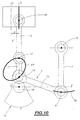
- Figure 9 shows the trajectories of the moving parts of the device for a given position of the hinge pin 9 of the rod 7 on the adjustment member 8: for a given position of this adjustment point 9, the crankpin 14 describes a circle not shown around the fixed pin 16.
- the axis 17 of the link 3 describes an ellipse E1 while the piston 2 moves according to the vertical axis XX.
- the rod 7 performs a pendulum movement around its axis of articulation 9 and serves as a reaction element. If we move axis 9, either vertically or according to some law in a plane, we modify and the position of the piston 2 at the end of the stroke, and the elliptical trajectory E of the axis 17 of the link 3, and the law of motion of all of these two parts.
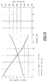
- Figure 12 gives an example of the simultaneous evolution of the ratio volumetric (on the ordinate on the left), and the displacement in cubic centimeters (on the y-axis on the right), depending on the setting of the axis position 9 in range P (in mm), Figure 11.
- the positions of the axes 17, 6, 9, the relative lengths of the arms 11 and 12 of the master rod 4, and the angle that these arms form between them, thus that the length of the balance rod 7, are chosen to obtain the variation desired rate and preferably an inverse variation of the displacement. AT a high rate will correspond to a reduced displacement, and vice versa.
- the angle arms 11 and 12 of the main connecting rod 4 is preferably between 100 and approximately 130 °. This spacing of the arms makes it possible to reduce the forces on the balance rod 7, and therefore on the actuator 20, which can be reduced pilot power consumption.
- the ratio between the lengths of the short arm 11 and the long arm 12 is between 0.6 and 0.8 allowing a ratio of displacement (small displacement on large displacement) of 0.75 and 0.60 for a variation in compression ratio respectively of the order of 7 points and 4.5 rate points.
- Another element adjustment is the offset d from the initial XX axis of cylinder 1, to a position X'X '(figure 10), preferably in the direction opposite to the axes articulation 6, 9 with respect to the initial axis XX.
- This parameter modifies the obliquity of the rod 3 in operation and the position of the dead centers.
- the direction of rotation of the crankshaft 15 is arbitrary, but such that shown, in front view, the pendulum 7 to the right of the axis XX, the direction preferential rotation is that of clockwise.
- the trajectory of the articulation point 9 between the link 7 and the adjustment member 8 is linear.
- the trajectory of this articulation point 9 is curvilinear. In this case, when the articulation point 9 reaches its position high maximum, it approaches the axis of cylinder 1 and the angle between the connecting rod main 4 and the link 7 is reduced.
- Curve C1 is the oscillating trajectory traveled by the end lower 6 of articulation of the connecting rod 7 when its axis of articulation 9 is in high position 9 (H), and the curve C2 corresponds to the trajectory of its axis articulation 6 for a lower position 9B of its upper end 9.
- the ellipse E1 is traversed by the axis 17 of articulation of the link slave 3 when the balance rod 7 is in the high position 9H and the piston 2 is in the lowest top dead center position (PMHb).
- the E2 ellipse is traversed by the axis 17 of the slave link 3 when the axis 9 of the pendulum 7 is in the extreme low position 9B and the piston 2 is in the neutral position highest highest (TDCh).
- the strong stroke C3 of the piston 2 is delimited by its neutral point high “low” (TDC b) and by its bottom dead center low “low” (PMB b): this race C3 is the distance between the positions of piston 2 in Figure 7 and the Figure 8 (strong stroke, weak rate).
- the short stroke C4 of piston 2 is delimited by a top dead center position (TDC h) located higher than the position top dead center (TDC b), and the bottom dead center position (PMB h), located at a height higher than that of the bottom dead center of the strong stroke C3 (PMB b); this short stroke C4 corresponds to the stroke of the piston 2 between the positions of figure 5 and figure 6.
- the invention is applicable to all engine architectures and to all types of fuels.
- the invention is not limited to the embodiment described and can include many variations of execution.
Landscapes
- Engineering & Computer Science (AREA)
- Chemical & Material Sciences (AREA)
- Combustion & Propulsion (AREA)
- Mechanical Engineering (AREA)
- General Engineering & Computer Science (AREA)
- Output Control And Ontrol Of Special Type Engine (AREA)
- Shafts, Cranks, Connecting Bars, And Related Bearings (AREA)
Abstract
Description
- modification du volume mort côté culasse par un piston additionnel,
- longueur de bielle variable,
- piston « gonflable »,
- distance axe de vilebrequin - plan de joint de culasse variable,
- course variable.
- la plage P est la hauteur de réglage de l'axe d'articulation 9 de la biellette balancier 7 entre le point haut 9(H) et le point bas 9(B) sur une amplitude P.
- avantages théoriques :
- amélioration du rendement à charge partielle quand on augmente le taux de compression et que l'on réduit la cylindrée unitaire (effet de taux plus effet « down sizing » à faible charge),
- augmentation possible du taux de suralimentation hors cliquetis lorsque le rapport volumétrique est réduit (nouvel effet « down sizing » mais en pleine charge),
- gestion de la post-détente (cycle Atkinson) sur une grande plage d'utilisation,
- fonctionnement en modes de combustion particuliers: auto-allumage, mélange pauvre homogène, forte recirculation de gaz.
- variation possible de la cylindrée dans des proportions supérieures à 25% pour une variation de rapport volumétrique de 100%,
- la technologie utilisée connue pour les divers composants de l'ensemble (assemblage type bielle et biellette),
- compacité et masse du dispositif de variation de course.
Claims (8)
- Moteur à combustion interne, comprenant au moins un cylindre (1) dans lequel peut se déplacer un piston (2) entre un point mort haut et un point mort bas, caractérisé en ce qu'il comprend des moyens pour faire varier la positon du point mort haut (PMH) entre des limites prédéterminées afin de faire varier simultanément la course (C3, C4) du piston, la position du point mort bas (PMB) et corrélativement le rapport volumétrique et la cylindrée en fonction des conditions d'utilisation du moteur.
- Moteur selon la revendication 1, caractérisé en ce que lesdits moyens comprennent une bielle (3) articulée d'une part sur le piston (2) et d'autre part sur une bielle principale (4) qui tourne sur un vilebrequin (15), et en ce que ladite bielle principale (4) est également articulée sur une biellette (7) formant balancier, associée à un organe (8) de réglage de la position de ladite biellette commandant les positions des points morts haut et bas.
- Moteur selon la revendication 2, caractérisé en ce que la bielle principale (4) comporte un bras court (11) entre un maneton (14) du vilebrequin (15) et un axe (17) de la bielle (3) et un bras long (12) entre ledit maneton et un axe d'articulation (6) sur ladite biellette (7) formant balancier.
- Moteur selon la revendication 3, caractérisé en ce que l'angle que les bras (11, 12) de la bielle principale (4) forment entre eux est compris entre 100 et 130° environ.
- Moteur selon la revendication 3 ou 4, caractérisé en ce que le rapport entre les longeurs du bras court (11) et du bras long (12) est compris entre 0,6 et 0,8.
- Moteur selon l'une quelconque des revendications 2 à 5, caractérisé en ce que la trajectoire du point d'articulation (9) entre la bielle principale (4) et la biellette (7) est linéaire.
- Moteur selon l'une quelconque des revendications 2 à 5, caractérisé en ce que la trajectoire du point d'articulation (9) entre la bielle principale (4) et la biellette est curviligne.
- Moteur selon l'une quelconque des revendications 2 à 7, caractérisé en ce que l'organe de réglage (8) coopère avec un actionneur (20).
Applications Claiming Priority (2)
| Application Number | Priority Date | Filing Date | Title |
|---|---|---|---|
| FR0004298A FR2807105B1 (fr) | 2000-04-04 | 2000-04-04 | Moteur a combustion interne, a rapport volumetrique et a cylindree variables |
| FR0004298 | 2000-04-04 |
Publications (2)
| Publication Number | Publication Date |
|---|---|
| EP1143127A1 true EP1143127A1 (fr) | 2001-10-10 |
| EP1143127B1 EP1143127B1 (fr) | 2005-03-16 |
Family
ID=8848858
Family Applications (1)
| Application Number | Title | Priority Date | Filing Date |
|---|---|---|---|
| EP01400802A Expired - Lifetime EP1143127B1 (fr) | 2000-04-04 | 2001-03-28 | Moteur à combustion interne, à rapport volumétrique et à cylindrée variables |
Country Status (4)
| Country | Link |
|---|---|
| EP (1) | EP1143127B1 (fr) |
| AT (1) | ATE291160T1 (fr) |
| DE (1) | DE60109342T2 (fr) |
| FR (1) | FR2807105B1 (fr) |
Cited By (6)
| Publication number | Priority date | Publication date | Assignee | Title |
|---|---|---|---|---|
| WO2002012694A1 (fr) * | 2000-08-08 | 2002-02-14 | Daimlerchrysler Ag | Moteur a combustion interne a piston alternatif, a taux de compression variable |
| WO2004053345A1 (fr) * | 2002-12-11 | 2004-06-24 | Dapomot Oy | Mecanisme a manivelle de moteur a combustion |
| EP1496219A1 (fr) * | 2003-07-08 | 2005-01-12 | HONDA MOTOR CO., Ltd. | Moteur à combustion avec taux de compression variable |
| CN105745418A (zh) * | 2013-11-14 | 2016-07-06 | 奥迪股份公司 | 内燃机的多联杆曲柄传动机构以及相应的内燃机 |
| CN112855357A (zh) * | 2021-01-24 | 2021-05-28 | 效俊林 | 内燃机可变活塞行程可变压缩比机构及控制方法 |
| CN113958405A (zh) * | 2021-10-28 | 2022-01-21 | 谢占鳌 | 一种高效率节油内燃机 |
Families Citing this family (10)
| Publication number | Priority date | Publication date | Assignee | Title |
|---|---|---|---|---|
| FR2910545B1 (fr) | 2006-12-20 | 2012-06-08 | Inst Francais Du Petrole | Moteur a combustion interne a cylindree variable et/ou a taux de compression variable avec un basculeur entre le vilebrequin et la bielle et procede pour realiser de telles variations. |
| DE102010032427A1 (de) | 2010-07-28 | 2012-02-02 | Daimler Ag | Stelleinrichtung für eine Hubkolbenmaschine sowie Verfahren zum Betreiben einer solchen Hubkolbenmaschine |
| DE102010032425A1 (de) | 2010-07-28 | 2012-02-02 | Daimler Ag | Stelleinrichtung für eine Hubkolbenmaschine, Hubkolbenmaschine sowie Verfahren zum Betreiben einer solchen Hubkolbenmaschine |
| DE102010032489A1 (de) | 2010-07-28 | 2012-02-02 | Daimler Ag | Stelleinrichtung für eine Hubkolbenmaschine, Hubkolbenmaschine sowie Verfahren zum Betreiben einer solchen Hubkolbenmaschine |
| DE102010032433A1 (de) | 2010-07-28 | 2012-02-02 | Daimler Ag | Hubkolbenmaschine, insbesondere für einen Kraftwagen, sowie Verfahren zum Betreiben einer Hubkolbenmaschine |
| DE102010032490A1 (de) | 2010-07-28 | 2012-02-02 | Daimler Ag | Hubkolbenmaschine, insbesondere für einen Kraftwagen, sowie Verfahren zum Betreiben einer solchen Hubkolbenmaschine |
| DE102012007465B4 (de) | 2012-04-13 | 2014-09-11 | Audi Ag | Brennkraftmaschine |
| US8794200B2 (en) * | 2012-11-21 | 2014-08-05 | GM Global Technology Operations LLC | Engine assembly with phasing mechanism on eccentric shaft for variable cycle engine |
| DE102014221250A1 (de) * | 2014-10-20 | 2016-04-21 | Bayerische Motoren Werke Aktiengesellschaft | Verbrennungskraftmaschine eines Kraftfahrzeugs und Kraftfahrzeug |
| DE102015015616A1 (de) * | 2015-12-03 | 2017-06-08 | Audi Ag | Mehrgelenkskurbeltrieb für eine Brennkraftmaschine, Brennkraftmaschine mit einem Mehrgelenkskurbeltrieb sowie Verfahren zum Betreiben eines Mehrgelenkskurbeltriebs |
Citations (4)
| Publication number | Priority date | Publication date | Assignee | Title |
|---|---|---|---|---|
| EP0898644A1 (fr) | 1996-05-13 | 1999-03-03 | Broadsuper Limited | Moteurs a combustion interne |
| DE29913107U1 (de) * | 1999-07-27 | 1999-10-07 | Fend, Fritz, 93138 Lappersdorf | Verbrennungsmotor |
| WO2000008325A1 (fr) * | 1998-08-04 | 2000-02-17 | Oezdamar Hasan Basri | Systeme a excentrique et ressort pour moteurs a pistons a combustion interne ou externe |
| EP1012459A1 (fr) | 1997-09-12 | 2000-06-28 | Preservation Holdings Limited | Moteurs a combustion interne |
-
2000
- 2000-04-04 FR FR0004298A patent/FR2807105B1/fr not_active Expired - Fee Related
-
2001
- 2001-03-28 DE DE60109342T patent/DE60109342T2/de not_active Expired - Fee Related
- 2001-03-28 AT AT01400802T patent/ATE291160T1/de not_active IP Right Cessation
- 2001-03-28 EP EP01400802A patent/EP1143127B1/fr not_active Expired - Lifetime
Patent Citations (4)
| Publication number | Priority date | Publication date | Assignee | Title |
|---|---|---|---|---|
| EP0898644A1 (fr) | 1996-05-13 | 1999-03-03 | Broadsuper Limited | Moteurs a combustion interne |
| EP1012459A1 (fr) | 1997-09-12 | 2000-06-28 | Preservation Holdings Limited | Moteurs a combustion interne |
| WO2000008325A1 (fr) * | 1998-08-04 | 2000-02-17 | Oezdamar Hasan Basri | Systeme a excentrique et ressort pour moteurs a pistons a combustion interne ou externe |
| DE29913107U1 (de) * | 1999-07-27 | 1999-10-07 | Fend, Fritz, 93138 Lappersdorf | Verbrennungsmotor |
Non-Patent Citations (1)
| Title |
|---|
| H.N.POULIOT: "DESIGNING A VARIABLE STROKE ENGINE", AUTOMOTIVE ENGINEERING, vol. 85, no. 6, 1 June 1977 (1977-06-01), pages 50 - 55, XP002152859 * |
Cited By (12)
| Publication number | Priority date | Publication date | Assignee | Title |
|---|---|---|---|---|
| WO2002012694A1 (fr) * | 2000-08-08 | 2002-02-14 | Daimlerchrysler Ag | Moteur a combustion interne a piston alternatif, a taux de compression variable |
| US6772717B2 (en) | 2000-08-08 | 2004-08-10 | Daimlerchrysler Ag | Reciprocating piston internal combustion engine |
| WO2004053345A1 (fr) * | 2002-12-11 | 2004-06-24 | Dapomot Oy | Mecanisme a manivelle de moteur a combustion |
| EP1496219A1 (fr) * | 2003-07-08 | 2005-01-12 | HONDA MOTOR CO., Ltd. | Moteur à combustion avec taux de compression variable |
| US7021254B2 (en) | 2003-07-08 | 2006-04-04 | Honda Motor Co., Ltd. | Engine with variably adjustable compression ratio, and methods of using same |
| CN105745418A (zh) * | 2013-11-14 | 2016-07-06 | 奥迪股份公司 | 内燃机的多联杆曲柄传动机构以及相应的内燃机 |
| US9982596B2 (en) | 2013-11-14 | 2018-05-29 | Audi Ag | Multi-joint crank drive of an internal combustion engine and corresponding internal combustion engine |
| CN105745418B (zh) * | 2013-11-14 | 2018-12-07 | 奥迪股份公司 | 内燃机的多联杆曲柄传动机构以及相应的内燃机 |
| CN112855357A (zh) * | 2021-01-24 | 2021-05-28 | 效俊林 | 内燃机可变活塞行程可变压缩比机构及控制方法 |
| CN112855357B (zh) * | 2021-01-24 | 2023-04-18 | 效俊林 | 内燃机可变活塞行程可变压缩比机构及控制方法 |
| CN113958405A (zh) * | 2021-10-28 | 2022-01-21 | 谢占鳌 | 一种高效率节油内燃机 |
| CN113958405B (zh) * | 2021-10-28 | 2024-05-28 | 谢占鳌 | 一种高效率节油内燃机 |
Also Published As
| Publication number | Publication date |
|---|---|
| FR2807105A1 (fr) | 2001-10-05 |
| EP1143127B1 (fr) | 2005-03-16 |
| DE60109342D1 (de) | 2005-04-21 |
| DE60109342T2 (de) | 2005-08-04 |
| ATE291160T1 (de) | 2005-04-15 |
| FR2807105B1 (fr) | 2008-11-14 |
Similar Documents
| Publication | Publication Date | Title |
|---|---|---|
| EP1143127B1 (fr) | Moteur à combustion interne, à rapport volumétrique et à cylindrée variables | |
| JP3845617B2 (ja) | ピストン式内燃機関 | |
| NL1009211C2 (nl) | Kruk-drijfstangmechanisme. | |
| EP1170482B1 (fr) | Mécanisme pour la variation des taux de compression d' un moteur à combustion interne | |
| JP3362227B2 (ja) | 内燃機関の弁を可変制御するための装置、特に火花点火機関を非絞り負荷制御するための装置 | |
| US5680840A (en) | Multi-crankshaft variable stroke engine | |
| US7174863B2 (en) | Mechanism for internal combustion piston engines | |
| EP1238189B1 (fr) | Dispositif pour modifier le taux de compression afin d'optimiser le fonctionnement des moteurs a pistons alternatifs | |
| EP2281107B1 (fr) | Moteur pourvu d'une chambre a volume variable | |
| FR2573481A1 (fr) | Moteur a mecanisme a coulisse avec course et taux de compression variables | |
| EP1023531B1 (fr) | Procede de controle du mouvement de piston de machine, dispositif de mise en oeuvre et equilibrage du dispositif | |
| JPH07509550A (ja) | 差動ストローク内燃機関 | |
| WO2003089764A1 (fr) | Detendeur a debit variable et distribution par soupape a commande progressive pour moteur a injection d'air comprime fonctionnant en mono et pluri energie et autres moteurs ou compresseurs | |
| RU2256085C2 (ru) | Поршневой двигатель внутреннего сгорания с переменной степенью сжатия | |
| FR2647508A1 (fr) | Moteur a combustion interne a taux de compression variable | |
| RU2121590C1 (ru) | Способ регулирования многотопливного двигателя внутреннего сгорания с увеличенным ходом поршня методом изменения степени сжатия и многотопливный двигатель внутреннего сгорания с увеличенным ходом поршня | |
| RU98107031A (ru) | Способ регулирования многотопливного двигателя внутреннего сгорания с увеличенным ходом поршня методом изменения степени сжатия и многотопливный двигатель внутреннего сгорания с увеличенным ходом поршня | |
| FR2906332A1 (fr) | Dispositif de transformation d'un mouvement lineaire en un mouvement de rotation de facon reglable | |
| FR2802973A1 (fr) | Moteur a combustion interne a cylindree et taux de compression variables | |
| RU2114314C1 (ru) | Способ регулирования мощности двигателя внутреннего сгорания и двигатель внутреннего сгорания | |
| RU2476691C2 (ru) | Регулируемый привод клапана впуска рабочей среды в цилиндр двигателя | |
| FR2461813A1 (fr) | Dispositif de variation du couple d'un mecanisme a pistons | |
| FR2828910A1 (fr) | Architecture cinematique pour moteur thermique quatre temps classique a pistons a combustion interne | |
| FR2801932A1 (fr) | Procede et dispositif pour modifier et prendre en compte le taux de compression pour optimiser le fonctionnement des moteurs a pistons alternatifs | |
| FR2821643A1 (fr) | Chambre d'expansion de moteur a air comprime |
Legal Events
| Date | Code | Title | Description |
|---|---|---|---|
| PUAI | Public reference made under article 153(3) epc to a published international application that has entered the european phase |
Free format text: ORIGINAL CODE: 0009012 |
|
| AK | Designated contracting states |
Kind code of ref document: A1 Designated state(s): AT BE CH CY DE DK ES FI FR GB GR IE IT LI LU MC NL PT SE TR |
|
| AX | Request for extension of the european patent |
Free format text: AL;LT;LV;MK;RO;SI |
|
| TPAD | Observations filed by third parties |
Free format text: ORIGINAL CODE: EPIDOS TIPA |
|
| 17P | Request for examination filed |
Effective date: 20020315 |
|
| AKX | Designation fees paid |
Free format text: AT BE CH CY DE DK ES FI FR GB GR IE IT LI LU MC NL PT SE TR |
|
| 17Q | First examination report despatched |
Effective date: 20040311 |
|
| GRAP | Despatch of communication of intention to grant a patent |
Free format text: ORIGINAL CODE: EPIDOSNIGR1 |
|
| GRAS | Grant fee paid |
Free format text: ORIGINAL CODE: EPIDOSNIGR3 |
|
| GRAA | (expected) grant |
Free format text: ORIGINAL CODE: 0009210 |
|
| AK | Designated contracting states |
Kind code of ref document: B1 Designated state(s): AT BE CH CY DE DK ES FI FR GB GR IE IT LI LU MC NL PT SE TR |
|
| PG25 | Lapsed in a contracting state [announced via postgrant information from national office to epo] |
Ref country code: NL Free format text: LAPSE BECAUSE OF FAILURE TO SUBMIT A TRANSLATION OF THE DESCRIPTION OR TO PAY THE FEE WITHIN THE PRESCRIBED TIME-LIMIT Effective date: 20050316 Ref country code: AT Free format text: LAPSE BECAUSE OF FAILURE TO SUBMIT A TRANSLATION OF THE DESCRIPTION OR TO PAY THE FEE WITHIN THE PRESCRIBED TIME-LIMIT Effective date: 20050316 Ref country code: FI Free format text: LAPSE BECAUSE OF FAILURE TO SUBMIT A TRANSLATION OF THE DESCRIPTION OR TO PAY THE FEE WITHIN THE PRESCRIBED TIME-LIMIT Effective date: 20050316 Ref country code: IE Free format text: LAPSE BECAUSE OF FAILURE TO SUBMIT A TRANSLATION OF THE DESCRIPTION OR TO PAY THE FEE WITHIN THE PRESCRIBED TIME-LIMIT Effective date: 20050316 Ref country code: TR Free format text: LAPSE BECAUSE OF FAILURE TO SUBMIT A TRANSLATION OF THE DESCRIPTION OR TO PAY THE FEE WITHIN THE PRESCRIBED TIME-LIMIT Effective date: 20050316 |
|
| REG | Reference to a national code |
Ref country code: GB Ref legal event code: FG4D Free format text: NOT ENGLISH |
|
| PG25 | Lapsed in a contracting state [announced via postgrant information from national office to epo] |
Ref country code: CY Free format text: LAPSE BECAUSE OF FAILURE TO SUBMIT A TRANSLATION OF THE DESCRIPTION OR TO PAY THE FEE WITHIN THE PRESCRIBED TIME-LIMIT Effective date: 20050328 Ref country code: LU Free format text: LAPSE BECAUSE OF NON-PAYMENT OF DUE FEES Effective date: 20050328 |
|
| PG25 | Lapsed in a contracting state [announced via postgrant information from national office to epo] |
Ref country code: LI Free format text: LAPSE BECAUSE OF NON-PAYMENT OF DUE FEES Effective date: 20050331 Ref country code: CH Free format text: LAPSE BECAUSE OF NON-PAYMENT OF DUE FEES Effective date: 20050331 Ref country code: MC Free format text: LAPSE BECAUSE OF NON-PAYMENT OF DUE FEES Effective date: 20050331 Ref country code: BE Free format text: LAPSE BECAUSE OF NON-PAYMENT OF DUE FEES Effective date: 20050331 |
|
| REG | Reference to a national code |
Ref country code: CH Ref legal event code: EP |
|
| REG | Reference to a national code |
Ref country code: IE Ref legal event code: FG4D Free format text: FRENCH |
|
| REF | Corresponds to: |
Ref document number: 60109342 Country of ref document: DE Date of ref document: 20050421 Kind code of ref document: P |
|
| PG25 | Lapsed in a contracting state [announced via postgrant information from national office to epo] |
Ref country code: GR Free format text: LAPSE BECAUSE OF FAILURE TO SUBMIT A TRANSLATION OF THE DESCRIPTION OR TO PAY THE FEE WITHIN THE PRESCRIBED TIME-LIMIT Effective date: 20050616 Ref country code: DK Free format text: LAPSE BECAUSE OF FAILURE TO SUBMIT A TRANSLATION OF THE DESCRIPTION OR TO PAY THE FEE WITHIN THE PRESCRIBED TIME-LIMIT Effective date: 20050616 |
|
| PG25 | Lapsed in a contracting state [announced via postgrant information from national office to epo] |
Ref country code: ES Free format text: LAPSE BECAUSE OF FAILURE TO SUBMIT A TRANSLATION OF THE DESCRIPTION OR TO PAY THE FEE WITHIN THE PRESCRIBED TIME-LIMIT Effective date: 20050627 |
|
| GBT | Gb: translation of ep patent filed (gb section 77(6)(a)/1977) |
Effective date: 20050622 |
|
| NLV1 | Nl: lapsed or annulled due to failure to fulfill the requirements of art. 29p and 29m of the patents act | ||
| PG25 | Lapsed in a contracting state [announced via postgrant information from national office to epo] |
Ref country code: PT Free format text: LAPSE BECAUSE OF FAILURE TO SUBMIT A TRANSLATION OF THE DESCRIPTION OR TO PAY THE FEE WITHIN THE PRESCRIBED TIME-LIMIT Effective date: 20050907 |
|
| BERE | Be: lapsed |
Owner name: PEUGEOT CITROEN AUTOMOBILES SA Effective date: 20050331 |
|
| REG | Reference to a national code |
Ref country code: IE Ref legal event code: FD4D |
|
| REG | Reference to a national code |
Ref country code: CH Ref legal event code: PL |
|
| PLBE | No opposition filed within time limit |
Free format text: ORIGINAL CODE: 0009261 |
|
| STAA | Information on the status of an ep patent application or granted ep patent |
Free format text: STATUS: NO OPPOSITION FILED WITHIN TIME LIMIT |
|
| PG25 | Lapsed in a contracting state [announced via postgrant information from national office to epo] |
Ref country code: FR Free format text: LAPSE BECAUSE OF NON-PAYMENT OF DUE FEES Effective date: 20060131 |
|
| 26N | No opposition filed |
Effective date: 20051219 |
|
| REG | Reference to a national code |
Ref country code: FR Ref legal event code: ST Effective date: 20060131 |
|
| PGFP | Annual fee paid to national office [announced via postgrant information from national office to epo] |
Ref country code: FR Payment date: 20060329 Year of fee payment: 6 |
|
| REG | Reference to a national code |
Ref country code: GB Ref legal event code: 746 Effective date: 20070116 |
|
| REG | Reference to a national code |
Ref country code: FR Ref legal event code: IC |
|
| BERE | Be: lapsed |
Owner name: PEUGEOT CITROEN AUTOMOBILES SA Effective date: 20050331 |
|
| PG25 | Lapsed in a contracting state [announced via postgrant information from national office to epo] |
Ref country code: SE Free format text: LAPSE BECAUSE OF FAILURE TO SUBMIT A TRANSLATION OF THE DESCRIPTION OR TO PAY THE FEE WITHIN THE PRESCRIBED TIME-LIMIT Effective date: 20050616 |
|
| PGFP | Annual fee paid to national office [announced via postgrant information from national office to epo] |
Ref country code: GB Payment date: 20080225 Year of fee payment: 8 Ref country code: IT Payment date: 20080307 Year of fee payment: 8 |
|
| PGFP | Annual fee paid to national office [announced via postgrant information from national office to epo] |
Ref country code: DE Payment date: 20080312 Year of fee payment: 8 |
|
| PG25 | Lapsed in a contracting state [announced via postgrant information from national office to epo] |
Ref country code: FR Free format text: LAPSE BECAUSE OF NON-PAYMENT OF DUE FEES Effective date: 20050331 |
|
| GBPC | Gb: european patent ceased through non-payment of renewal fee |
Effective date: 20090328 |
|
| PG25 | Lapsed in a contracting state [announced via postgrant information from national office to epo] |
Ref country code: DE Free format text: LAPSE BECAUSE OF NON-PAYMENT OF DUE FEES Effective date: 20091001 |
|
| PG25 | Lapsed in a contracting state [announced via postgrant information from national office to epo] |
Ref country code: GB Free format text: LAPSE BECAUSE OF NON-PAYMENT OF DUE FEES Effective date: 20090328 |
|
| PG25 | Lapsed in a contracting state [announced via postgrant information from national office to epo] |
Ref country code: IT Free format text: LAPSE BECAUSE OF NON-PAYMENT OF DUE FEES Effective date: 20090328 |