EP1142818A1 - Untersichtverkleidung für Fahrtreppen und Fahrsteige - Google Patents
Untersichtverkleidung für Fahrtreppen und Fahrsteige Download PDFInfo
- Publication number
- EP1142818A1 EP1142818A1 EP01106619A EP01106619A EP1142818A1 EP 1142818 A1 EP1142818 A1 EP 1142818A1 EP 01106619 A EP01106619 A EP 01106619A EP 01106619 A EP01106619 A EP 01106619A EP 1142818 A1 EP1142818 A1 EP 1142818A1
- Authority
- EP
- European Patent Office
- Prior art keywords
- escalator
- profile
- moving walk
- truss
- fastening
- Prior art date
- Legal status (The legal status is an assumption and is not a legal conclusion. Google has not performed a legal analysis and makes no representation as to the accuracy of the status listed.)
- Granted
Links
- 238000005253 cladding Methods 0.000 claims description 20
- 238000010079 rubber tapping Methods 0.000 description 3
- 229910000831 Steel Inorganic materials 0.000 description 1
- 229910052782 aluminium Inorganic materials 0.000 description 1
- XAGFODPZIPBFFR-UHFFFAOYSA-N aluminium Chemical compound [Al] XAGFODPZIPBFFR-UHFFFAOYSA-N 0.000 description 1
- 230000000712 assembly Effects 0.000 description 1
- 238000000429 assembly Methods 0.000 description 1
- 238000012423 maintenance Methods 0.000 description 1
- 239000000463 material Substances 0.000 description 1
- 229910052751 metal Inorganic materials 0.000 description 1
- 239000002184 metal Substances 0.000 description 1
- 239000000843 powder Substances 0.000 description 1
- 238000009420 retrofitting Methods 0.000 description 1
- 229910001220 stainless steel Inorganic materials 0.000 description 1
- 239000010935 stainless steel Substances 0.000 description 1
- 239000010959 steel Substances 0.000 description 1
Images

Classifications
-
- B—PERFORMING OPERATIONS; TRANSPORTING
- B66—HOISTING; LIFTING; HAULING
- B66B—ELEVATORS; ESCALATORS OR MOVING WALKWAYS
- B66B23/00—Component parts of escalators or moving walkways
Definitions
- the present invention relates to an escalator and a Moving walk with a truss and a soffit cladding. It also concerns a soffit cladding for one Escalator or moving walk.
- the soffit cladding is to the dimensions of the truss individually adjusted, or the tolerances are determined using a decorative angle between the side panel and the bottom panel concealed.
- the mounting blocks on profiles, which are connected to the truss with fastening screws are screwed on, the mounting blocks at least on one side of the escalator or moving walk have an elongated hole for each fastening screw.
- the longitudinal direction of the slot is transverse to the escalator or to the moving walk. This allows tolerances in the transverse direction compensate because each mounting block is in the longitudinal direction of the elongated hole through which the fastening screw passes, can be postponed. If the soffit panel on the mounting blocks with self-tapping screws is screwed, tolerances in the longitudinal direction are less critical.
- the profiles can be u-profiles with their legs on Truss or on a bottom sheet metal that matches the truss is connected, welded.
- the profiles can also be c-profiles that are based on the framework or on a bottom view plate, which is connected to the truss, are screwed on. This option is especially for one subsequent retrofitting is advisable.
- the mounting blocks are also possible to use the mounting blocks to tolerances to compensate in the longitudinal direction.
- the fastening screws are screwed into a clamping plate are behind the slot of the c-profile or lie behind the oblong holes of the u-profile
- the clamping plates are designed so that they are in a position by the Slot of the c-profile or through the elongated holes of the u-profile fit that - starting from this position - can rotate a maximum of about 90 ° in the profile and that they in this twisted position not through the slot of the c-profile or through the elongated holes of the u-profile.
- the Tolerance compensation in the longitudinal direction is done by the entire unit consisting of mounting block, screw and Clamping plate in the slot of the c-profile or in the elongated holes of the u-profile is shifted.
- the assembly is done by brings the unit to the profile so that the clamping plate passes through the slot of the c-profile or through the slot of the u-profile fits. If you now turn the fastening screw, first turn the clamping plate by about 90 ° until it strikes in profile. Then the fastening screw is screwed into the clamping plate until the mounting block - previously moved to the right place - clamped.
- a suitable form for the clamping plates is the parallelogram. With this shape you can get the properties you want (can be inserted into a slot in one position; can be rotated a maximum of about 90 ° in profile and fits in this twisted position not easily through the slot) and reach reliably.
- a bottom view cladding according to the invention for an escalator or moving walk through it characterized that they bend on both sides has and that attached to these bends clamping springs are.
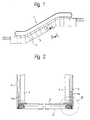
- FIG. 1 shows a side view an escalator
- Fig. 2 shows a section along the line A-A in Fig. 1
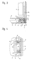
- Fig. 3 shows the area B of Fig. 2 in an enlarged View
- Fig. 4 is a view according to arrow C of Fig. 3
- Fig. 5 a view similar to Figure 3 of another embodiment.
- 6 is a view according to arrow C in Fig. 5th
- the escalator 1 has a side panel 3 and a bottom panel 2 on.
- Truss 4 (see Fig. 2) with truss angles 4a, 4b is a Bottom view plate 5 welded on.
- this bottom view plate 5 On this bottom view plate 5 are left and right two u-profiles 6 (see Fig. 3 and 4) attached by welded joint.
- the bottom sheet 5 can but can also be omitted; then the u-profiles 6 welded directly to the truss angles 4a, 4b.
- the u-profile 6 has two for each mounting block 7 Elongated holes 12 (see Fig. 4).
- the mounting block 7 has two slots 11 (see also Fig. 3) through which one fastening screw 9 each. Every fastening screw 9 is provided with a locking washer 10 and in a clamping plate 8, which is located in the u-profile 6, screwed.
- the fastening screw 9 is loosened, the Mounting block 7 because of the elongated holes 12 in the longitudinal direction the escalator 1 (up and down, as seen in Fig. 4) and due to the elongated holes 11 in the transverse direction of the escalator 1 (shifted to the left and right as seen in Fig. 4) become. By tightening the fastening screws 9 the mounting block 7 in the correctly adjusted position fixed.
- the clamping plate 8 has the shape of a Parallelogram.
- the length and width of this parallelogram are slightly less than the length and width of the Elongated holes 12 so that the clamping plate 8 through the elongated holes 12 fits.
- the diagonal of the parallelogram is however longer than the inner width of the u-profile 6, so that the Clamping plate 8 can only be rotated by about 90 ° in the u-profile 6 can after going through the slot 12 into the interior of the u-profile 6 was introduced. It strikes in this position the legs of the u-profile 6 (this is the one in FIG. 4 drawn position).
- the soffit panel 2 has bends on both sides, and the Screws 13 with which the underside cladding 2 is screwed on is enforce these bends. The screws 13 are therefore to the side and are not visible from below.
- clamping springs 14 At the bends there are also clamping springs 14 by means of rivets 15 attached. At these clamping springs 14 is the side panel 3 attached. The side panel 3 covers the Screws 13 and the clamping springs 14 off, so that these also the page are not visible.
- the cladding is installed as follows: In each mounting block 7 are already two mounting screws 9 with lock washers 10 and clamping plates 8 pre-assembled. The two clamping plates 8 are aligned in parallel to the elongated holes 12 and brings the mounting block 7th roughly in its target position; the clamping plates 8 are now in the elongated holes 12. By pushing in the fastening screws 9 and turn slightly clockwise the clamping plates 8 in the position shown in FIGS. 3 and 4. Then you bring the mounting block 7 as precisely as possible its target position and tightening the fastening screws 9. After placing all mounting blocks 7 in position has, you push the bottom cladding 2 with their Bends on the mounting blocks 7 and screws them by means of the screws 13. This is done most rationally Assembly with self-tapping screws or self-tapping screws. Finally, the side panel 3 is then by means of the Clamping springs 14 attached to the soffit cladding 2.
- the modified embodiment according to FIGS. 5 and 6 differs by the fact that instead of the welded u-profile 6 a c-profile 16 is provided.
- This c profile 16 is at its base with screws 17 at the truss angles 4b screwed on.
- the slot of the c-profile 16 replaces there the elongated holes 12 of the u-profile 6.
- the mounting blocks 7 can therefore at any point in the longitudinal direction of the Escalator to be attached.
- the elements of the soffit cladding can be different Materials (e.g. painted sheet steel, powder-coated, Stainless steel, aluminum).
Landscapes
- Escalators And Moving Walkways (AREA)
Abstract
Description
Claims (8)
- Fahrtreppe (1) bzw. Fahrsteig mit einem Fachwerk (4) und einer Untersichtverkleidung (2), dadurch gekennzeichnet, dass die Untersichtverkleidung (2) an ihren seitlichen Rändern jeweils eine Umbiegung aufweist, dass die Untersichtverkleidung an diesen Umbiegungen mit Befestigungsklötzen (7) verschraubt (Schrauben 13) ist, und dass die Befestigungsklötze (7) mit dem Fachwerk (4) verbunden sind, wobei die Verbindung der Befestigungsklötze (7) zumindest an einer Seite der Fahrtreppe bzw. des Fahrsteiges einen Toleranzausgleich zulässt.
- Fahrtreppe (1) bzw. Fahrsteig nach Anspruch 1, dadurch gekennzeichnet, dass die Befestigungsklötze (7) an Profilen (6, 16), welche mit dem Fachwerk (4) verbunden sind, mit Befestigungsschrauben (9) angeschraubt sind, wobei die Befestigungsklötze (7) zumindest an einer Seite der Fahrtreppe (1) bzw. des Fahrsteiges für jede Befestigungsschraube (9) ein Langloch (11) aufweisen.
- Fahrtreppe (1) bzw. Fahrsteig nach Anspruch 2, dadurch gekennzeichnet, dass die Profile u-Profile (6) sind, die mit ihren Schenkeln am Fachwerk (4) oder an einem Untersichtblech (5), das mit dem Fachwerk (4) verbunden ist, angeschweißt sind.
- Fahrtreppe (1) bzw. Fahrsteig nach Anspruch 2, dadurch gekennzeichnet, dass die Profile c-Profile (16) sind, die mit ihrer Basis am Fachwerk (4) oder an einem Untersichtblech (5), das mit dem Fachwerk (4) verbunden ist, angeschraubt sind.
- Fahrtreppe (1) bzw. Fahrsteig nach Anspruch 3 oder 4, dadurch gekennzeichnet, dass die Befestigungsschrauben (9) in eine Klemmplatte (8) eingeschraubt sind, die hinter dem Schlitz des c-Profils (16) bzw. hinter Langlöchern (12) des u-Profils (6) liegen, wobei die Klemmplatten (8) so ausgebildet sind, dass sie in einer Stellung durch den Schlitz des c-Profils (16) bzw. durch die Langlöcher (12) des u-Profils (6) passen, dass sie sich - ausgehend von dieser Stellung - maximal um etwa 90° im Profil (6, 16) drehen können und dass sie in dieser verdrehten Stellung nicht durch den Schlitz des c-Profils (16) bzw. durch die Langlöcher (12) des u-Profils (6) passen.
- Fahrtreppe (1) bzw. Fahrsteig nach Anspruch 5, dadurch gekennzeichnet, dass die Klemmplatten (8) etwa die Form eines Parallelogramms aufweisen.
- Fahrtreppe (1) bzw. Fahrsteig nach einem der Ansprüche 1 bis 6, dadurch gekennzeichnet, dass an den Umbiegungen der Untersichtverkleidung (2) Klemmfedern (14) für eine Seitenverkleidung (3) angebracht sind.
- Untersichtverkleidung (2) für eine Fahrtreppe (1) bzw. einen Fahrsteig, dadurch gekennzeichnet, dass sie an beiden Seiten eine Umbiegung aufweist und dass an diesen Umbiegungen Klemmfedern (14) angebracht sind.
Priority Applications (1)
| Application Number | Priority Date | Filing Date | Title |
|---|---|---|---|
| EP20010106619 EP1142818B1 (de) | 2000-03-31 | 2001-03-16 | Untersichtverkleidung für Fahrtreppen und Fahrsteige |
Applications Claiming Priority (3)
| Application Number | Priority Date | Filing Date | Title |
|---|---|---|---|
| EP00810269 | 2000-03-31 | ||
| EP00810269 | 2000-03-31 | ||
| EP20010106619 EP1142818B1 (de) | 2000-03-31 | 2001-03-16 | Untersichtverkleidung für Fahrtreppen und Fahrsteige |
Publications (2)
| Publication Number | Publication Date |
|---|---|
| EP1142818A1 true EP1142818A1 (de) | 2001-10-10 |
| EP1142818B1 EP1142818B1 (de) | 2006-10-04 |
Family
ID=26073832
Family Applications (1)
| Application Number | Title | Priority Date | Filing Date |
|---|---|---|---|
| EP20010106619 Expired - Lifetime EP1142818B1 (de) | 2000-03-31 | 2001-03-16 | Untersichtverkleidung für Fahrtreppen und Fahrsteige |
Country Status (1)
| Country | Link |
|---|---|
| EP (1) | EP1142818B1 (de) |
Citations (2)
| Publication number | Priority date | Publication date | Assignee | Title |
|---|---|---|---|---|
| JPH10101283A (ja) * | 1996-09-30 | 1998-04-21 | Toshiba Elevator Technos Kk | 乗客コンベアの外装装置 |
| JPH11236182A (ja) * | 1998-02-23 | 1999-08-31 | Muramatsu Kogyo:Kk | 斜面移動装置用外装体 |
-
2001
- 2001-03-16 EP EP20010106619 patent/EP1142818B1/de not_active Expired - Lifetime
Patent Citations (2)
| Publication number | Priority date | Publication date | Assignee | Title |
|---|---|---|---|---|
| JPH10101283A (ja) * | 1996-09-30 | 1998-04-21 | Toshiba Elevator Technos Kk | 乗客コンベアの外装装置 |
| JPH11236182A (ja) * | 1998-02-23 | 1999-08-31 | Muramatsu Kogyo:Kk | 斜面移動装置用外装体 |
Non-Patent Citations (2)
| Title |
|---|
| PATENT ABSTRACTS OF JAPAN vol. 1998, no. 09 31 July 1998 (1998-07-31) * |
| PATENT ABSTRACTS OF JAPAN vol. 1999, no. 13 30 November 1999 (1999-11-30) * |
Also Published As
| Publication number | Publication date |
|---|---|
| EP1142818B1 (de) | 2006-10-04 |
Similar Documents
| Publication | Publication Date | Title |
|---|---|---|
| EP1152112A2 (de) | Verstellbare Scharnier-Rahmen-Anordnung | |
| DE69616388T2 (de) | Aufzugskabinenraum | |
| DE1683009B2 (de) | Falttür mit mindestens zwei Tafeln | |
| EP0185188B1 (de) | Kabine | |
| DE102006052854B4 (de) | Großraumkabine zur Behandlung von Werkstücken | |
| DE19739644C2 (de) | Wand für die Kabine einer Lackieranlage | |
| DE2814713A1 (de) | Zerlegbare trennwand | |
| EP3091133B1 (de) | Haltesystem für wandelemente | |
| EP1142818B1 (de) | Untersichtverkleidung für Fahrtreppen und Fahrsteige | |
| DE3719829C2 (de) | ||
| CH672000A5 (de) | ||
| EP0647476A1 (de) | Wandkonstruktion für eine Kabine einer Lackieranlage | |
| DE19719113A1 (de) | Türsystem | |
| DE4220844C2 (de) | Standgestell für ein Gehäuse, insbesondere einer Briefkasten- und/oder Türsprechanlage | |
| DE3708278C2 (de) | Selbsttragendes Wandelement zum Aufbau einer Wandkonstruktion insbesondere auf Schiffen oder Offshore-Bauten | |
| EP1589164B1 (de) | An eine Gebäudewand anbaubare Kabine | |
| EP0230998A2 (de) | Torblatt mit Belüftungsöffnungen | |
| DE2501759A1 (de) | Umkleidekabinensystem aus vorgespanntem glas | |
| DE10323347B4 (de) | Treppe und Tragkonstruktion einer Treppe | |
| DE9320706U1 (de) | Wandkonstruktion für eine Kabine einer Lackieranlage | |
| DE9211932U1 (de) | Schienensystem für Schiebetüren sowie Schiebetürsystem | |
| DE29922479U1 (de) | Wandsegment für eine Wand einer Kabine | |
| EP1241316A2 (de) | Zerlegbare Kipptor-Vorrichtung | |
| DE29922481U1 (de) | Vorrichtung zur verfahrbaren Anordnung einer Schiebetür an einer Türöffnung | |
| DE29905094U1 (de) | Duschanordnung |
Legal Events
| Date | Code | Title | Description |
|---|---|---|---|
| PUAI | Public reference made under article 153(3) epc to a published international application that has entered the european phase |
Free format text: ORIGINAL CODE: 0009012 |
|
| AK | Designated contracting states |
Kind code of ref document: A1 Designated state(s): AT CH DE FR GB LI Kind code of ref document: A1 Designated state(s): AT BE CH CY DE DK ES FI FR GB GR IE IT LI LU MC NL PT SE TR |
|
| AX | Request for extension of the european patent |
Free format text: AL;LT;LV;MK;RO;SI |
|
| 17P | Request for examination filed |
Effective date: 20020320 |
|
| AKX | Designation fees paid |
Free format text: AT CH DE FR GB LI |
|
| GRAP | Despatch of communication of intention to grant a patent |
Free format text: ORIGINAL CODE: EPIDOSNIGR1 |
|
| GRAS | Grant fee paid |
Free format text: ORIGINAL CODE: EPIDOSNIGR3 |
|
| GRAA | (expected) grant |
Free format text: ORIGINAL CODE: 0009210 |
|
| AK | Designated contracting states |
Kind code of ref document: B1 Designated state(s): AT CH DE FR GB LI |
|
| REG | Reference to a national code |
Ref country code: GB Ref legal event code: FG4D Free format text: NOT ENGLISH |
|
| REG | Reference to a national code |
Ref country code: CH Ref legal event code: EP |
|
| REF | Corresponds to: |
Ref document number: 50111122 Country of ref document: DE Date of ref document: 20061116 Kind code of ref document: P |
|
| GBT | Gb: translation of ep patent filed (gb section 77(6)(a)/1977) |
Effective date: 20061108 |
|
| ET | Fr: translation filed | ||
| PLBE | No opposition filed within time limit |
Free format text: ORIGINAL CODE: 0009261 |
|
| STAA | Information on the status of an ep patent application or granted ep patent |
Free format text: STATUS: NO OPPOSITION FILED WITHIN TIME LIMIT |
|
| 26N | No opposition filed |
Effective date: 20070705 |
|
| REG | Reference to a national code |
Ref country code: FR Ref legal event code: PLFP Year of fee payment: 16 |
|
| REG | Reference to a national code |
Ref country code: FR Ref legal event code: PLFP Year of fee payment: 17 |
|
| REG | Reference to a national code |
Ref country code: FR Ref legal event code: PLFP Year of fee payment: 18 |
|
| PGFP | Annual fee paid to national office [announced via postgrant information from national office to epo] |
Ref country code: CH Payment date: 20190320 Year of fee payment: 19 Ref country code: GB Payment date: 20190320 Year of fee payment: 19 Ref country code: FR Payment date: 20190322 Year of fee payment: 19 Ref country code: DE Payment date: 20190321 Year of fee payment: 19 |
|
| PGFP | Annual fee paid to national office [announced via postgrant information from national office to epo] |
Ref country code: AT Payment date: 20190321 Year of fee payment: 19 |
|
| REG | Reference to a national code |
Ref country code: DE Ref legal event code: R119 Ref document number: 50111122 Country of ref document: DE |
|
| REG | Reference to a national code |
Ref country code: CH Ref legal event code: PL |
|
| REG | Reference to a national code |
Ref country code: AT Ref legal event code: MM01 Ref document number: 341519 Country of ref document: AT Kind code of ref document: T Effective date: 20200316 |
|
| PG25 | Lapsed in a contracting state [announced via postgrant information from national office to epo] |
Ref country code: CH Free format text: LAPSE BECAUSE OF NON-PAYMENT OF DUE FEES Effective date: 20200331 Ref country code: FR Free format text: LAPSE BECAUSE OF NON-PAYMENT OF DUE FEES Effective date: 20200331 Ref country code: LI Free format text: LAPSE BECAUSE OF NON-PAYMENT OF DUE FEES Effective date: 20200331 Ref country code: DE Free format text: LAPSE BECAUSE OF NON-PAYMENT OF DUE FEES Effective date: 20201001 Ref country code: AT Free format text: LAPSE BECAUSE OF NON-PAYMENT OF DUE FEES Effective date: 20200316 |
|
| GBPC | Gb: european patent ceased through non-payment of renewal fee |
Effective date: 20200316 |
|
| PG25 | Lapsed in a contracting state [announced via postgrant information from national office to epo] |
Ref country code: GB Free format text: LAPSE BECAUSE OF NON-PAYMENT OF DUE FEES Effective date: 20200316 |