EP1142208B1 - Verfahren und einrichtung zur sendesignalüberwachung - Google Patents
Verfahren und einrichtung zur sendesignalüberwachung Download PDFInfo
- Publication number
- EP1142208B1 EP1142208B1 EP00904832A EP00904832A EP1142208B1 EP 1142208 B1 EP1142208 B1 EP 1142208B1 EP 00904832 A EP00904832 A EP 00904832A EP 00904832 A EP00904832 A EP 00904832A EP 1142208 B1 EP1142208 B1 EP 1142208B1
- Authority
- EP
- European Patent Office
- Prior art keywords
- bus
- signal
- transmitter
- circuit
- message signal
- Prior art date
- Legal status (The legal status is an assumption and is not a legal conclusion. Google has not performed a legal analysis and makes no representation as to the accuracy of the status listed.)
- Expired - Lifetime
Links
- 238000000034 method Methods 0.000 title claims abstract description 8
- 230000005540 biological transmission Effects 0.000 title description 15
- 238000012544 monitoring process Methods 0.000 claims description 11
- 238000005516 engineering process Methods 0.000 claims description 3
- 238000009434 installation Methods 0.000 claims description 3
- 238000011144 upstream manufacturing Methods 0.000 claims 1
- 238000004891 communication Methods 0.000 description 6
- 239000004020 conductor Substances 0.000 description 3
- 230000000903 blocking effect Effects 0.000 description 1
- 230000015556 catabolic process Effects 0.000 description 1
- 230000008878 coupling Effects 0.000 description 1
- 238000010168 coupling process Methods 0.000 description 1
- 238000005859 coupling reaction Methods 0.000 description 1
- 238000010586 diagram Methods 0.000 description 1
- 238000011156 evaluation Methods 0.000 description 1
- 238000012806 monitoring device Methods 0.000 description 1
Images
Classifications
-
- H—ELECTRICITY
- H04—ELECTRIC COMMUNICATION TECHNIQUE
- H04L—TRANSMISSION OF DIGITAL INFORMATION, e.g. TELEGRAPHIC COMMUNICATION
- H04L25/00—Baseband systems
- H04L25/02—Details ; arrangements for supplying electrical power along data transmission lines
- H04L25/08—Modifications for reducing interference; Modifications for reducing effects due to line faults ; Receiver end arrangements for detecting or overcoming line faults
- H04L25/085—Arrangements for reducing interference in line transmission systems, e.g. by differential transmission
Definitions
- the invention relates firstly to a method for transmitting and receiving according to the preamble of claim 1, as well as to a transmitting and receiving stage according to the preamble of claim 2, wherein the functional check a sent signal is compared with a returning signal. The returning signal indicates the transmitted signal.
- the invention relates to a method and apparatus for transmitting and receiving a bus of building system technology that carries power and message signals, particularly at the bus of the EIBA (European Installation Bus Association).
- a dispatched message signal is compared with the message signal returning from the bus to check the function.
- a bus coupling unit of a transmitting bus station compares its transmission signal with the signal returning from the bus, which is sent back to another function control by another station. By such a comparison, one can detect an error of the transmission stage or the reception stage. If the sent and the returning signal are different, this is understood as an error message from the system. The transmission stage is then disabled in order to avoid erroneous behavior of the subscriber and a fault in the system. Other facilities work according to this principle. Such an error message is also unfounded in functioning transmission stage when the vehicle electrical system voltage drops, for example, due to a voltage breakdown on the bus so far that the evaluation in comparison of the message sent and the returning message is no longer properly possible. In one In such a case, the transmission stage would be blocked unfounded and the subscriber shut down without cause.
- a device for communication monitoring is already known from EP 0 664 628 A2.
- a bus with two lines is checked for its functionality. If one of the two lines does not work, the device detects the error and outputs an error signal.
- this device is used for communication monitoring and possibly to maintain communication over only one bus line.
- the feedback on the respective state of the device and the bus is similar to a control loop, the bus lines are used as part of the control loop.
- the disadvantage here is that regardless of the error is a shutdown of individual communication components.
- the feedback via the bus lines can also lead to faults.
- the invention has for its object to develop a method for transmitting and receiving, in which the monitoring of the transmission signal does not lead to unfounded shutdowns.
- the procedure is such that in the event of a voltage drop on the bus below a predetermined value at which the message signal returning from the bus can no longer be sufficiently reliably evaluated, the message signals to be sent are fed directly to the receiver.
- the monitoring is performed directly without detour via the bus, so that when sending a signal and a comparison is possible.
- the solution of the described task is also carried out by a transmitting and receiving stage according to claim 2. It is again assumed that the functional check a sent message signal is compared with the returning from the bus message signal, a mismatch leads to setting an error flag and locks the station ,
- the solution of the described object is achieved in that the receiver is connected at its output with an OR circuit, wherein the input of the transmitter is connected to an AND circuit, with which also an output of a device for monitoring the bus voltage is connected.
- the output of the AND circuit is also connected to an input of the OR circuit. At a bus voltage below a predetermined value of the voltage monitoring device, a signal is output to the AND circuit.
- the AND circuit forwards a signal to the one input of the OR circuit, which, regardless of whether a signal runs back, passes on a signal, as is the case with an intact transmission circuit. If there is sufficient voltage, the voltage monitoring does not emit a signal, so that no signal is passed on by the AND circuit. When the signal is received, the OR circuit passes on a signal, as it corresponds to a functioning transmission stage. If the transmitter is faulty, no return signal can be received so that no signal is present at the OR circuit from the receiver. When the voltage is intact, voltage monitoring indicates the AND circuit no signal. Although the transmission voltage applied to the transmitter passes as a signal to the AND circuit, which, however, can not pass on a signal since no signal is present at its second signal.
- the receiver can not receive a returning signal, so that no signal comes to the OR circuit, so that they can not deliver a signal.
- the circuit acts in the event of a voltage dip as if the transmit signal were fed back directly to the receiver without going through a bus.
- the AND circuit and the OR circuit are in the form of a pending signal when they are able to output a signal.
- a signal comparison device can be arranged in front of the input of the transmitter and behind the output of the receiver, which can compare and evaluate the transmission signal to the transmitter with the signal received by the receiver.
- the transmitting and receiving stage and / or the comparison device can be designed as an integrated circuit, as an IC.
- the described circuit arrangements are particularly suitable for this purpose.
- the integrated circuit may be of the so-called UART type.
- UART Universal Asynchronous Receiver Transmitter
- TP UART Twisted Pair.
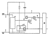
- the device for transmitting signal monitoring operates with a transmitting and receiving stage 1 for a bus with the bus conductors 2 for VB + with the positive bus potential and the bus conductor. 3 for VB- with the negative bus potential.
- This type is typical for the bus of the EIBA, but the device also works accordingly for other bus devices or other line systems in a circuit arrangement. These conductors then perform the function of a bus in the sense of the invention.
- a transmitter 4 and a receiver 5 are executed.
- the individual components can be embodied in their functions in an integrated circuit, in an IC, in particular in a UART. To check the function of the transmitter 4 a sent message signal is compared with the returning from the bus to the receiver 5 message signal.
- the lockout flag is commonly referred to as an error flag.
- the receiver 5 is connected at its output to an OR circuit 6, wherein the input of the transmitter 4 is connected to an AND circuit 7 in connection.
- the AND circuit 7 is also connected to an output of a device 8 for monitoring the bus voltage.
- the output of the AND circuit 7 is connected to the input of the OR circuit 6.
- the voltage monitoring outputs a signal to the AND circuit when falling below a predetermined value of the bus voltage.
- the device acts in such a way that a transmission signal pending at the transmitter 4 is returned directly to the receiver 5 without the detour via the bus line. In the exemplary embodiment, it is coupled to the receiving line 9 via the OR circuit 6.
- a comparison of the transmission signal with the receiver signal can be carried out in a comparison device 10, which is arranged in the embodiment before the input of the transmitter 4 and behind the output of the receiver 5.
- the transmitting and receiving stage 1, like the comparator 10, may be implemented in an integrated circuit, also in a common integrated circuit.
- the transmitting and receiving stage 1 can be designed as UART and for a bus with twisted pair cable as TPUART.
Landscapes
- Engineering & Computer Science (AREA)
- Power Engineering (AREA)
- Computer Networks & Wireless Communication (AREA)
- Signal Processing (AREA)
- Small-Scale Networks (AREA)
- Selective Calling Equipment (AREA)
- Communication Control (AREA)
- Monitoring And Testing Of Transmission In General (AREA)
- Dc Digital Transmission (AREA)
- Radar Systems Or Details Thereof (AREA)
Description
- Die Erfindung bezieht sich zunächst auf ein Verfahren zum Senden und Empfangen gemäß dem Oberbegriff des Anspruchs 1, sowie auf eine Sende- und Empfangsstufe gemäß dem Oberbegriff des Anspruchs 2, wobei zur Funktionskontrolle ein abgesandtes Signal mit einem zurücklaufenden Signal verglichen wird. Das zurücklaufende Signal gibt hierbei das abgesandte Signal wieder.
- Die Erfindung bezieht sich insbesondere auf ein Verfahren und auf eine Einrichtung zum Senden und Empfangen bei einem Bus der Gebäudesystemtechnik, der Energie und Nachrichtensignale führt, insbesondere beim Bus der EIBA (European Installation Bus Association). Bei einem derartigen Bus wird zur Funktionskontrolle ein abgesandtes Nachrichtensignal mit dem vom Bus zurücklaufenden Nachrichtensignal verglichen.
- Bei derartigen Bussystemen vergleicht ein Busankoppler eines sendenden Busteilnehmers sein Sendesignal mit dem vom Bus zurücklaufenden Signal, das von einem anderen Teilnehmer zur Funktionskontrolle zurückgesandt wird. Durch einen derartigen Vergleich kann man einen Fehler der Sendestufe oder der Empfangsstufe detektieren. Sind das abgesandte und das zurücklaufende Signal unterschiedlich, wird dies als Fehlermeldung vom System verstanden. Die Sendestufe wird dann gesperrt, um ein fehlerhaftes Verhalten des Teilnehmers und eine Störung des Systems zu vermeiden. Nach diesem Prinzip arbeiten auch andere Einrichtungen. Eine derartige Fehlermeldung entsteht aber auch unbegründet bei funktionierender Sendestufe, wenn die Bordnetzspannung beispielsweise infolge eines Spannungszusammenbruchs auf dem Bus soweit absinkt, dass die Auswertung im Vergleich der gesendeten Nachricht und der rücklaufenden Nachricht nicht mehr ordnungsgemäß möglich ist. In einem solchen Fall würde die Sendestufe unbegründet gesperrt und der Teilnehmer ohne Grund abgeschaltet.
- Die Funktion einer Einrichtung zur Kommunikationsüberwachung ist bereits aus der EP 0 664 628 A2 bekannt. Hierbei wird ein Bus mit zwei Leitungen auf seine Funktionsfähigkeit überprüft. Sofern eine von beiden Leitungen nicht funktioniert, erkennt die Einrichtung den Fehler und gibt ein Fehlersignal aus.
- Dieses bewirkt, dass ein der fehlerbehafteten Leitung zugeordnetes Kommunikationsbauteil, welches zur Sendeprioritätssteuerung dient, funktionslos und damit geschützt wird. Andererseits wird durch einen Auswahlvorgang in der Einrichtung das System auf eine Kommunikation über nur eine Busleitung umgeschaltet.
- Insgesamt betrachtet, dient diese Einrichtung zur Kommunikationsüberwachung und ggf. zur Aufrechterhaltung der Kommunikation über nur eine Busleitung. Die Rückkopplung über den jeweiligen Zustand der Einrichtung und des Busses erfolgt dabei ähnlich einem Regelkreis, wobei die Busleitungen als Teil des Regelkreises genutzt werden.
- Nachteilig ist hierbei, dass unabhängig vom Fehler eine Abschaltung einzelner Kommunikationsbauteile erfolgt. Die Rückkopplung über die Busleitungen kann ebenfalls zu Störungen führen.
- Der Erfindung liegt die Aufgabe zugrunde, ein Verfahren zum Senden und Empfangen zu entwickeln, bei dem die Überwachung des Sendesignals nicht zu unbegründeten Abschaltungen führt.
- Die Lösung der geschilderten Aufgabe erfolgt nach der Erfindung durch ein Verfahren nach Anspruch 1. Dadurch wird sichergestellt, dass die Sendeschaltung nur bei einem Fehler abgeschaltet wird, nicht jedoch bei Spannungseinbrüchen.
- Dabei wird bei einem Bus derart verfahren, dass im Falle eines Spannungseinbruchs auf dem Bus unter einen vorgegebenen Wert, bei dem das vom Bus zurücklaufenden Nachrichtensignal nicht mehr hinreichend sicher auswertbar ist, abzusendende Nachrichtensignale direkt dem Empfänger zugeführt werden. Hierdurch wird die Überwachung ohne Umweg über den Bus unmittelbar durchgeführt, so dass bei Absenden eines Signals auch ein Vergleich möglich ist.
- Die Lösung der geschilderten Aufgabe erfolgt auch durch eine Sende- und Empfangsstufe nach Anspruch 2. Es wird wieder davon ausgegangen, dass zur Funktionskontrolle ein abgesandtes Nachrichtensignal mit dem vom Bus zurücklaufenden Nachrichtensignal verglichen wird, wobei eine Nichtübereinstimmung zum Setzen eines Fehlerflags führt und die Station sperrt. Die Lösung der geschilderten Aufgabe erfolgt dadurch, dass der Empfänger an seinem Ausgang mit einer ODER-Schaltung verbunden ist, wobei der Eingang des Senders mit einer UND-Schaltung in Verbindung steht, mit der auch ein Ausgang einer Einrichtung zum Überwachung der Busspannung verbunden ist. Hierbei ist der Ausgang der UND-Schaltung auch mit einem Eingang der ODER-Schaltung verbunden. Bei einer Busspannung unterhalb eines vorgegebenen Wertes der Einrichtung für die Spannungsüberwachung wird an die UND-Schaltung ein Signal abgegeben. Wenn zugleich ein Sendesignal ansteht, gibt die UND-Schaltung ein Signal an den einen Eingang der ODER-Schaltung weiter, die unabhängig davon, ob ein Signal zurückläuft, ein Signal weitergibt, wie es bei einer intakten Sendeschaltung der Fall ist. Bei ausreichender Spannung gibt die Spannungsüberwachung kein Signal ab, so dass auch von der UND-Schaltung kein Signal weitergegeben wird. Bei empfangenem Signal gibt die ODER-Schaltung ein Signal weiter, wie es einer funktionierenden Sendestufe entspricht. Wenn der Sender defekt ist, kann kein rücklaufendes Signal empfangen werden, so dass an der ODER-Schaltung vom Empfänger kein Signal ansteht. Bei intakter Spannung gibt die Spannungsüberwachung an die UND-Schaltung kein Signal ab. Die am Sender anstehende Sendespannung gelangt zwar als Signal zur UND-Schaltung, die jedoch kein Signal weitergeben kann, da an ihrem zweiten Signal kein Signal ansteht. Wenn der Sender defekt ist, kann der Empfänger kein rücklaufendes Signal empfangen, so dass zur ODER-Schaltung kein Signal gelangt, so dass sie auch kein Signal abgeben kann. Die Schaltung wirkt im Fall eines Spannungseinbruchs so, als würde das Sendesignal direkt zum Empfänger, ohne über einen Bus zu laufen, zurückgeleitet würde. Hierbei geben die UND-Schaltung und die ODER-Schaltung die Form eines anstehenden Signals durch, wenn sie in der Lage sind, ein Signal abzugeben.
- Vor dem Eingang des Senders und hinter dem Ausgang des Empfängers kann eine Signalvergleichseinrichtung angeordnet sein, die das zum Sender laufende Sendesignal mit dem vom Empfänger erhaltenen Signal vergleichen und auswerten kann.
- Die Sende- und Empfangsstufe und bzw. oder die Vergleichseinrichtung können als integrierte Schaltung, als IC, ausgeführt sein. Die geschilderten Schaltungsanordnungen sind dafür besonders geeignet.
- Die integrierte Schaltung kann vom Typ eines sogenannten UARTs sein. Eine solche UART IC-Schaltung kann für verdrillte Leitungen als TPUART ausgeführt sein. UART steht für Universal Asynchronous Receiver Transmitter und TP vor UART steht für Twisted Pair.
- Die Erfindung soll nun anhand eines in der Zeichnung grob schematisch wiedergegebenen Ausführungsbeispiels, welches einen Funktionsschaltplan einer Sende- und Empfangsstufe zeigt, näher erläutert werden:
- Die Einrichtung zur Sendesignalüberwachung arbeitet mit einer Sende- und Empfangsstufe 1 für einen Bus mit den Busleitern 2 für VB+ mit dem positiven Buspotential und dem Busleiter 3 für VB- mit dem negativen Buspotential. Diese Art ist für den Bus der EIBA typisch, die Einrichtung funktioniert jedoch entsprechend auch für andere Buseinrichtungen oder andere Leitungssysteme in einer Schaltungsanordnung. Diese Leiter nehmen dann die Funktion eines Busses im Sinne der Erfindung wahr. In der Sende- und Empfangsstufe 1 sind ein Sender 4 und ein Empfänger 5 ausgeführt. Die einzelnen Bauelemente können in ihren Funktionen in einer integrierten Schaltung, in einem IC, insbesondere in einem UART, ausgebildet sein. Zur Funktionskontrolle des Senders 4 wird ein abgesandtes Nachrichtensignal mit dem vom Bus zum Empfänger 5 zurücklaufenden Nachrichtensignal verglichen. Im Falle eines Fehlers, wenn der Sender also nicht funktionstüchtig ist, wird die Station gesperrt und die Sperrung kenntlich gemacht. Das Kennzeichen für die Sperrung wird üblicherweise als Fehlerflag bezeichnet. Der Empfänger 5 ist an seinem Ausgang mit einer ODER-Schaltung 6 verbunden, wobei der Eingang des Senders 4 mit einer UND-Schaltung 7 in Verbindung steht. Die UND-Schaltung 7 steht auch mit einem Ausgang einer Einrichtung 8 zur Überwachung der Busspannung in Verbindung. Der Ausgang der UND-Schaltung 7 ist mit dem Eingang der ODER-Schaltung 6 verbunden. Die Spannungsüberwachung gibt bei Unterschreiten eines vorgegebenen Wertes der Busspannung ein Signal an die UND-Schaltung ab. Die Einrichtung wirkt so, dass ein am Sender 4 anstehendes Sendesignal direkt zum Empfänger 5 ohne den Umweg über die Busleitung zurückgegeben wird. Im Ausführungsbeispiel wird es auf die Empfangsleitung 9 über die ODER-Schaltung 6 eingekoppelt. Ein Vergleich des Sendesignals mit dem Empfängersignal kann in einer Vergleichseinrichtung 10 erfolgen, die im Ausführungsbeispiel vor dem Eingang des Sender 4 und hinter dem Ausgang des Empfängers 5 angeordnet ist. Die Sende- und Empfangsstufe 1 kann ebenso wie die Vergleichseinrichtung 10 in einem integrierten Schaltkreis, auch in einem gemeinsamen integrierten Schaltkreis, ausgeführt sein. Insbesondere kann die Sende- und Empfangsstufe 1 als UART und für einen Bus mit verdrillter Zweidrahtleitung als TPUART ausgeführt sein.
Claims (6)
- Verfahren zum Senden und Empfangen bei einem Bus (2, 3) der Gebäudesystemtechnik, der Energie und Nachrichtensignale führt,
insbesondere beim Bus der EIBA (European Installation Bus Association),
wobei zur Funktionskontrolle
ein von einem Sender (4) abgesandtes Nachrichtensignal mit dem vom Bus (2, 3) zurücklaufenden Nachrichtensignal verglichen wird,
dadurch gekennzeichnet, daß
die Busspannung überwacht wird und
im Falle eines Spannungseinbruchs auf dem Bus (2, 3) unter einen vorgegebenen Wert, bei dem das vom Bus (2, 3) zurücklaufende Nachrichtensignal nicht mehr hinreichend sicher auswertbar ist,
ein abzusendendes, dem Sender (4) zugeführtes Nachrichtensignal innerhalb einer Sende- und Empfangsstufe (1) direkt zu einer Empfangsleitung (9) ohne Umweg über den Bus (2, 3) zurückgeführt wird und an Stelle des nicht auswertbaren Nachrichtensignals mit sich selbst verglichen wird. - Sende- und Empfangsstufe (1) für einen Bus (2, 3) der Gebäudesystemtechnik, der Energie und Nachrichtensignale führt,
insbesondere beim Bus der EIBA (European Installation Bus Association),
wobei zur Funktionskontrolle ein abgesandtes Nachrichtensignal mit dem vom Bus (2, 3) zurücklaufenden Nachrichtensignal verglichen wird,
wobei eine Nichtübereinstimmung zum Setzen eines Fehlerflags führt und die Sendestufe (1) sperrt,
dadurch gekennzeichnet, daß
der Empfänger (5) an seinem Ausgang mit einer ODER-Schaltung (6) verbunden ist,
wobei der Eingang des Senders (4) mit einer UND-Schaltung (7) in Verbindung steht, mit der auch ein Ausgang einer Einrichtung (8) zum Überwachen der Busspannung verbunden ist,
wobei der Ausgang der UND-Schaltung (7) auch mit einem Eingang der ODER-Schaltung (6) verbunden ist. - Einrichtung nach Anspruch 2, dadurch gekennzeichnet, dass vor dem Eingang des Senders (4) und hinter dem Ausgang des Empfängers (5) eine Signalvergleichseinrichtung (10) angeordnet ist.
- Einrichtung nach Anspruch 2 oder 3, dadurch ge-kennzeichnet, dass die Sende- und Empfangsstufe (1) und bzw. oder die Vergleichseinrichtung (10) als IC ausgeführt ist.
- Einrichtung nach Anspruch 4, dadurch ge-kennzeichnet, dass der IC vom Typ eines sogenannten Universal Asynchronous Receiver Transmitter (UART) ist.
- Einrichtung nach Anspruch 5, dadurch ge-kennzeichnet, dass der Universal Asynchronous Receiver Transmitter (UART) für verdrillte Leitungen als Twisted Pair Universal Asynchronous Receiver Transmitter (TPUART) ausgeführt ist.
Applications Claiming Priority (3)
| Application Number | Priority Date | Filing Date | Title |
|---|---|---|---|
| DE19901193 | 1999-01-14 | ||
| DE19901193A DE19901193A1 (de) | 1999-01-14 | 1999-01-14 | Verfahren und Einrichtung zur Sendesignalüberwachung |
| PCT/DE2000/000035 WO2000041458A2 (de) | 1999-01-14 | 2000-01-04 | Verfahren und einrichtung zur sendesignalüberwachung |
Publications (2)
| Publication Number | Publication Date |
|---|---|
| EP1142208A2 EP1142208A2 (de) | 2001-10-10 |
| EP1142208B1 true EP1142208B1 (de) | 2006-03-22 |
Family
ID=7894239
Family Applications (1)
| Application Number | Title | Priority Date | Filing Date |
|---|---|---|---|
| EP00904832A Expired - Lifetime EP1142208B1 (de) | 1999-01-14 | 2000-01-04 | Verfahren und einrichtung zur sendesignalüberwachung |
Country Status (9)
| Country | Link |
|---|---|
| EP (1) | EP1142208B1 (de) |
| AT (1) | ATE321397T1 (de) |
| AU (1) | AU2657600A (de) |
| DE (2) | DE19901193A1 (de) |
| DK (1) | DK1142208T3 (de) |
| ES (1) | ES2261179T3 (de) |
| HK (1) | HK1040149B (de) |
| PT (1) | PT1142208E (de) |
| WO (1) | WO2000041458A2 (de) |
Family Cites Families (9)
| Publication number | Priority date | Publication date | Assignee | Title |
|---|---|---|---|---|
| DE2502375C3 (de) * | 1975-01-22 | 1983-02-24 | Licentia Patent-Verwaltungs-Gmbh, 6000 Frankfurt | Datenübertragungsverfahren mit von Hand ausgelöster Rückantwort |
| US5315533A (en) * | 1991-05-17 | 1994-05-24 | Best Power Technology, Inc. | Back-up uninterruptible power system |
| JPH0764817A (ja) * | 1993-08-30 | 1995-03-10 | Mitsubishi Electric Corp | 故障検出システム |
| JPH07177202A (ja) * | 1993-12-21 | 1995-07-14 | Mitsubishi Electric Corp | 通信制御装置 |
| DE4413467C1 (de) * | 1994-04-19 | 1995-09-28 | Siemens Ag | Verfahren zum energiearmen Abfragen von binären Zuständen über lange Leitungen |
| DE4421083C2 (de) * | 1994-06-16 | 1996-04-11 | Volkswagen Ag | Verfahren zur Überwachung einer seriellen Übertragung von digitalen Daten auf einer Ein-Draht-Multiplexverbindung zwischen untereinander kommunizierenden Signalverarbeitungsgeräten |
| JP2845155B2 (ja) * | 1995-02-07 | 1999-01-13 | 日本電気株式会社 | シングルチップマイクロコンピュータのエミュレーションチップ |
| DE19601881A1 (de) * | 1996-01-19 | 1997-07-24 | Siemens Ag | Überwachungseinrichtung für Strom- und Leistungsaufnahme |
| US5784558A (en) * | 1996-04-26 | 1998-07-21 | Integrated Network Corporation | Method and apparatus for testing of extended ISDN BRI service |
-
1999
- 1999-01-14 DE DE19901193A patent/DE19901193A1/de not_active Withdrawn
-
2000
- 2000-01-04 DE DE50012442T patent/DE50012442D1/de not_active Expired - Lifetime
- 2000-01-04 ES ES00904832T patent/ES2261179T3/es not_active Expired - Lifetime
- 2000-01-04 AU AU26576/00A patent/AU2657600A/en not_active Abandoned
- 2000-01-04 PT PT00904832T patent/PT1142208E/pt unknown
- 2000-01-04 AT AT00904832T patent/ATE321397T1/de active
- 2000-01-04 DK DK00904832T patent/DK1142208T3/da active
- 2000-01-04 HK HK02101687.4A patent/HK1040149B/zh not_active IP Right Cessation
- 2000-01-04 WO PCT/DE2000/000035 patent/WO2000041458A2/de not_active Ceased
- 2000-01-04 EP EP00904832A patent/EP1142208B1/de not_active Expired - Lifetime
Also Published As
| Publication number | Publication date |
|---|---|
| WO2000041458A2 (de) | 2000-07-20 |
| DE50012442D1 (de) | 2006-05-11 |
| DK1142208T3 (da) | 2006-07-17 |
| WO2000041458A3 (de) | 2000-11-16 |
| HK1040149B (zh) | 2006-08-11 |
| AU2657600A (en) | 2000-08-01 |
| ATE321397T1 (de) | 2006-04-15 |
| ES2261179T3 (es) | 2006-11-16 |
| PT1142208E (pt) | 2006-07-31 |
| EP1142208A2 (de) | 2001-10-10 |
| HK1040149A1 (en) | 2002-05-24 |
| DE19901193A1 (de) | 2000-07-20 |
Similar Documents
| Publication | Publication Date | Title |
|---|---|---|
| DE3919962C2 (de) | ||
| EP0382794B1 (de) | Netzwerkschnittstelle | |
| EP2720094B1 (de) | Sicherheitssystem | |
| DE19643092C2 (de) | Feld-Datenbussystem | |
| DE102009046062B3 (de) | Vorrichtung und Verfahren zur Übertragung von Daten über Netzwerk-Knoten eines Netzwerkes | |
| EP2720051A1 (de) | Sicherheitssystem | |
| EP1427086A1 (de) | Elektrisches Gerät und Verfahren zum Betreiben eines elektrischen Geräts | |
| DE102008029948B4 (de) | Überwachungssystem | |
| EP0150457B1 (de) | Schaltungsanordnung zum Anschalten eines Teilnehmers an eine Busleitung | |
| EP0395739B1 (de) | Verfahren zur steuerung und/oder überwachung und schaltungsanordnung zur durchführung des verfahrens | |
| WO2000062478A2 (de) | Bussystem | |
| DE102021120393B3 (de) | Verfahren und Verschaltung zum Betrieb eines Netzwerks oder Netzwerkabschnitts | |
| EP0890110B1 (de) | Verfahren zum prüfen der massekontaktierung von teilen eines vernetzten systems | |
| DE3012105A1 (de) | Daten-dialogsystem | |
| DE10343172B4 (de) | Datenübertragungsstrecke mit Einrichtung zur Prüfung der Datenintegrität | |
| DE3327489C2 (de) | ||
| DE102007058071A1 (de) | Verfahren und Vorrichtung zur Plausibilisierung einer Auswertung von sicherheitsrelevanten Signalen für ein Kraftfahrzeug | |
| EP1192551B1 (de) | Interface zum ankoppeln eines busteilnehmers an die busleitung eines bussystems | |
| DE102005001686B4 (de) | Schaltungsanordung zum Detektieren eines Kurzschlusses | |
| EP2452467B1 (de) | Signalübertragungsvorrichtung und fahrzeugkomponente | |
| WO2000041458A2 (de) | Verfahren und einrichtung zur sendesignalüberwachung | |
| EP4046339A1 (de) | Sichere prüfanordnung | |
| DE2034487C3 (de) | Schaltungsanordnung zur Erfassung und Auswertung von Störungen einer Nachrichtenübertragungsanlage | |
| WO2002080007A1 (de) | Busstation zum anschluss an ein bussystem für rückhaltemittel und/oder sensoren | |
| DE2338961A1 (de) | Verfahren und schaltungen zum ueberwachen und umschalten von betriebs- und ersatz-nachrichtenleitungen |
Legal Events
| Date | Code | Title | Description |
|---|---|---|---|
| PUAI | Public reference made under article 153(3) epc to a published international application that has entered the european phase |
Free format text: ORIGINAL CODE: 0009012 |
|
| 17P | Request for examination filed |
Effective date: 20010618 |
|
| AK | Designated contracting states |
Kind code of ref document: A2 Designated state(s): AT BE CH CY DE DK ES FI FR GB GR IE IT LI LU MC NL PT SE |
|
| 17Q | First examination report despatched |
Effective date: 20050317 |
|
| GRAP | Despatch of communication of intention to grant a patent |
Free format text: ORIGINAL CODE: EPIDOSNIGR1 |
|
| GRAS | Grant fee paid |
Free format text: ORIGINAL CODE: EPIDOSNIGR3 |
|
| GRAA | (expected) grant |
Free format text: ORIGINAL CODE: 0009210 |
|
| AK | Designated contracting states |
Kind code of ref document: B1 Designated state(s): AT BE CH CY DE DK ES FI FR GB GR IE IT LI LU MC NL PT SE |
|
| PG25 | Lapsed in a contracting state [announced via postgrant information from national office to epo] |
Ref country code: IE Free format text: LAPSE BECAUSE OF FAILURE TO SUBMIT A TRANSLATION OF THE DESCRIPTION OR TO PAY THE FEE WITHIN THE PRESCRIBED TIME-LIMIT Effective date: 20060322 Ref country code: IT Free format text: LAPSE BECAUSE OF FAILURE TO SUBMIT A TRANSLATION OF THE DESCRIPTION OR TO PAY THE FEE WITHIN THE PRESCRIBED TIME-LIMIT;WARNING: LAPSES OF ITALIAN PATENTS WITH EFFECTIVE DATE BEFORE 2007 MAY HAVE OCCURRED AT ANY TIME BEFORE 2007. THE CORRECT EFFECTIVE DATE MAY BE DIFFERENT FROM THE ONE RECORDED. Effective date: 20060322 |
|
| REG | Reference to a national code |
Ref country code: GB Ref legal event code: FG4D Free format text: NOT ENGLISH |
|
| REG | Reference to a national code |
Ref country code: CH Ref legal event code: NV Representative=s name: SIEMENS SCHWEIZ AG Ref country code: CH Ref legal event code: EP |
|
| GBT | Gb: translation of ep patent filed (gb section 77(6)(a)/1977) |
Effective date: 20060322 |
|
| REG | Reference to a national code |
Ref country code: IE Ref legal event code: FG4D Free format text: LANGUAGE OF EP DOCUMENT: GERMAN |
|
| REF | Corresponds to: |
Ref document number: 50012442 Country of ref document: DE Date of ref document: 20060511 Kind code of ref document: P |
|
| REG | Reference to a national code |
Ref country code: SE Ref legal event code: TRGR |
|
| REG | Reference to a national code |
Ref country code: DK Ref legal event code: T3 |
|
| REG | Reference to a national code |
Ref country code: PT Ref legal event code: SC4A Effective date: 20060530 |
|
| REG | Reference to a national code |
Ref country code: HK Ref legal event code: GR Ref document number: 1040149 Country of ref document: HK |
|
| ET | Fr: translation filed | ||
| REG | Reference to a national code |
Ref country code: IE Ref legal event code: FD4D |
|
| REG | Reference to a national code |
Ref country code: ES Ref legal event code: FG2A Ref document number: 2261179 Country of ref document: ES Kind code of ref document: T3 |
|
| PLBE | No opposition filed within time limit |
Free format text: ORIGINAL CODE: 0009261 |
|
| STAA | Information on the status of an ep patent application or granted ep patent |
Free format text: STATUS: NO OPPOSITION FILED WITHIN TIME LIMIT |
|
| PG25 | Lapsed in a contracting state [announced via postgrant information from national office to epo] |
Ref country code: MC Free format text: LAPSE BECAUSE OF NON-PAYMENT OF DUE FEES Effective date: 20070131 |
|
| 26N | No opposition filed |
Effective date: 20061227 |
|
| PGFP | Annual fee paid to national office [announced via postgrant information from national office to epo] |
Ref country code: FI Payment date: 20071211 Year of fee payment: 9 |
|
| PG25 | Lapsed in a contracting state [announced via postgrant information from national office to epo] |
Ref country code: GR Free format text: LAPSE BECAUSE OF FAILURE TO SUBMIT A TRANSLATION OF THE DESCRIPTION OR TO PAY THE FEE WITHIN THE PRESCRIBED TIME-LIMIT Effective date: 20060623 |
|
| PGFP | Annual fee paid to national office [announced via postgrant information from national office to epo] |
Ref country code: DK Payment date: 20080110 Year of fee payment: 9 |
|
| PGFP | Annual fee paid to national office [announced via postgrant information from national office to epo] |
Ref country code: NL Payment date: 20080111 Year of fee payment: 9 Ref country code: PT Payment date: 20080104 Year of fee payment: 9 Ref country code: SE Payment date: 20080110 Year of fee payment: 9 |
|
| PGFP | Annual fee paid to national office [announced via postgrant information from national office to epo] |
Ref country code: BE Payment date: 20080117 Year of fee payment: 9 |
|
| REG | Reference to a national code |
Ref country code: CH Ref legal event code: PCAR Free format text: SIEMENS SCHWEIZ AG;INTELLECTUAL PROPERTY FREILAGERSTRASSE 40;8047 ZUERICH (CH) |
|
| REG | Reference to a national code |
Ref country code: PT Ref legal event code: MM4A Free format text: LAPSE DUE TO NON-PAYMENT OF FEES Effective date: 20090706 |
|
| PG25 | Lapsed in a contracting state [announced via postgrant information from national office to epo] |
Ref country code: CY Free format text: LAPSE BECAUSE OF FAILURE TO SUBMIT A TRANSLATION OF THE DESCRIPTION OR TO PAY THE FEE WITHIN THE PRESCRIBED TIME-LIMIT Effective date: 20060322 Ref country code: LU Free format text: LAPSE BECAUSE OF NON-PAYMENT OF DUE FEES Effective date: 20070104 |
|
| EUG | Se: european patent has lapsed | ||
| NLV4 | Nl: lapsed or anulled due to non-payment of the annual fee |
Effective date: 20090801 |
|
| REG | Reference to a national code |
Ref country code: DK Ref legal event code: EBP |
|
| PG25 | Lapsed in a contracting state [announced via postgrant information from national office to epo] |
Ref country code: FI Free format text: LAPSE BECAUSE OF NON-PAYMENT OF DUE FEES Effective date: 20090104 Ref country code: PT Free format text: LAPSE BECAUSE OF NON-PAYMENT OF DUE FEES Effective date: 20090706 |
|
| PG25 | Lapsed in a contracting state [announced via postgrant information from national office to epo] |
Ref country code: NL Free format text: LAPSE BECAUSE OF NON-PAYMENT OF DUE FEES Effective date: 20090801 |
|
| PG25 | Lapsed in a contracting state [announced via postgrant information from national office to epo] |
Ref country code: BE Free format text: LAPSE BECAUSE OF NON-PAYMENT OF DUE FEES Effective date: 20090131 |
|
| PG25 | Lapsed in a contracting state [announced via postgrant information from national office to epo] |
Ref country code: DK Free format text: LAPSE BECAUSE OF NON-PAYMENT OF DUE FEES Effective date: 20090731 |
|
| PG25 | Lapsed in a contracting state [announced via postgrant information from national office to epo] |
Ref country code: SE Free format text: LAPSE BECAUSE OF NON-PAYMENT OF DUE FEES Effective date: 20090105 |
|
| REG | Reference to a national code |
Ref country code: CH Ref legal event code: PUE Owner name: SIEMENS SCHWEIZ AG, CH Free format text: FORMER OWNER: SIEMENS AKTIENGESELLSCHAFT, DE |
|
| REG | Reference to a national code |
Ref country code: GB Ref legal event code: 732E Free format text: REGISTERED BETWEEN 20150220 AND 20150225 |
|
| REG | Reference to a national code |
Ref country code: DE Ref legal event code: R081 Ref document number: 50012442 Country of ref document: DE Owner name: SIEMENS SCHWEIZ AG, CH Free format text: FORMER OWNER: SIEMENS AKTIENGESELLSCHAFT, 80333 MUENCHEN, DE Effective date: 20150407 |
|
| REG | Reference to a national code |
Ref country code: AT Ref legal event code: PC Ref document number: 321397 Country of ref document: AT Kind code of ref document: T Owner name: SIEMENS SCHWEIZ AG, CH Effective date: 20150421 |
|
| REG | Reference to a national code |
Ref country code: FR Ref legal event code: PLFP Year of fee payment: 17 |
|
| REG | Reference to a national code |
Ref country code: FR Ref legal event code: TP Owner name: SIEMENS SCHWEIZ AG, CH Effective date: 20160202 |
|
| REG | Reference to a national code |
Ref country code: ES Ref legal event code: PC2A Owner name: SIEMENS SCHWEIZ AG Effective date: 20160414 |
|
| PGFP | Annual fee paid to national office [announced via postgrant information from national office to epo] |
Ref country code: IT Payment date: 20160127 Year of fee payment: 17 Ref country code: ES Payment date: 20160223 Year of fee payment: 17 |
|
| PGFP | Annual fee paid to national office [announced via postgrant information from national office to epo] |
Ref country code: GB Payment date: 20160111 Year of fee payment: 17 Ref country code: FR Payment date: 20160115 Year of fee payment: 17 |
|
| PGFP | Annual fee paid to national office [announced via postgrant information from national office to epo] |
Ref country code: CH Payment date: 20160404 Year of fee payment: 17 |
|
| REG | Reference to a national code |
Ref country code: CH Ref legal event code: PL |
|
| GBPC | Gb: european patent ceased through non-payment of renewal fee |
Effective date: 20170104 |
|
| REG | Reference to a national code |
Ref country code: FR Ref legal event code: ST Effective date: 20170929 |
|
| PG25 | Lapsed in a contracting state [announced via postgrant information from national office to epo] |
Ref country code: FR Free format text: LAPSE BECAUSE OF NON-PAYMENT OF DUE FEES Effective date: 20170131 Ref country code: LI Free format text: LAPSE BECAUSE OF NON-PAYMENT OF DUE FEES Effective date: 20170131 Ref country code: CH Free format text: LAPSE BECAUSE OF NON-PAYMENT OF DUE FEES Effective date: 20170131 |
|
| PG25 | Lapsed in a contracting state [announced via postgrant information from national office to epo] |
Ref country code: GB Free format text: LAPSE BECAUSE OF NON-PAYMENT OF DUE FEES Effective date: 20170104 |
|
| PG25 | Lapsed in a contracting state [announced via postgrant information from national office to epo] |
Ref country code: IT Free format text: LAPSE BECAUSE OF NON-PAYMENT OF DUE FEES Effective date: 20170104 |
|
| PG25 | Lapsed in a contracting state [announced via postgrant information from national office to epo] |
Ref country code: ES Free format text: LAPSE BECAUSE OF NON-PAYMENT OF DUE FEES Effective date: 20170105 |
|
| REG | Reference to a national code |
Ref country code: ES Ref legal event code: FD2A Effective date: 20180627 |
|
| PGFP | Annual fee paid to national office [announced via postgrant information from national office to epo] |
Ref country code: DE Payment date: 20190319 Year of fee payment: 20 |
|
| PGFP | Annual fee paid to national office [announced via postgrant information from national office to epo] |
Ref country code: AT Payment date: 20181210 Year of fee payment: 20 |
|
| REG | Reference to a national code |
Ref country code: DE Ref legal event code: R071 Ref document number: 50012442 Country of ref document: DE |
|
| REG | Reference to a national code |
Ref country code: AT Ref legal event code: MK07 Ref document number: 321397 Country of ref document: AT Kind code of ref document: T Effective date: 20200104 |