EP1139903B1 - Procede et appareil permettant de placer et de fixer avec precision des appareils orthodontiques - Google Patents
Procede et appareil permettant de placer et de fixer avec precision des appareils orthodontiques Download PDFInfo
- Publication number
- EP1139903B1 EP1139903B1 EP99921614A EP99921614A EP1139903B1 EP 1139903 B1 EP1139903 B1 EP 1139903B1 EP 99921614 A EP99921614 A EP 99921614A EP 99921614 A EP99921614 A EP 99921614A EP 1139903 B1 EP1139903 B1 EP 1139903B1
- Authority
- EP
- European Patent Office
- Prior art keywords
- appliance
- replica
- transfer tray
- patient
- orthodontic
- Prior art date
- Legal status (The legal status is an assumption and is not a legal conclusion. Google has not performed a legal analysis and makes no representation as to the accuracy of the status listed.)
- Expired - Lifetime
Links
Images

Classifications
-
- A—HUMAN NECESSITIES
- A61—MEDICAL OR VETERINARY SCIENCE; HYGIENE
- A61C—DENTISTRY; APPARATUS OR METHODS FOR ORAL OR DENTAL HYGIENE
- A61C7/00—Orthodontics, i.e. obtaining or maintaining the desired position of teeth, e.g. by straightening, evening, regulating, separating, or by correcting malocclusions
- A61C7/12—Brackets; Arch wires; Combinations thereof; Accessories therefor
- A61C7/14—Brackets; Fixing brackets to teeth
- A61C7/146—Positioning or placement of brackets; Tools therefor
-
- B—PERFORMING OPERATIONS; TRANSPORTING
- B33—ADDITIVE MANUFACTURING TECHNOLOGY
- B33Y—ADDITIVE MANUFACTURING, i.e. MANUFACTURING OF THREE-DIMENSIONAL [3-D] OBJECTS BY ADDITIVE DEPOSITION, ADDITIVE AGGLOMERATION OR ADDITIVE LAYERING, e.g. BY 3-D PRINTING, STEREOLITHOGRAPHY OR SELECTIVE LASER SINTERING
- B33Y80/00—Products made by additive manufacturing
Definitions
- This invention relates to a method and apparatus for bonding orthodontic appliances such as brackets to a patient's teeth. More specifically, the present invention relates to a bonding method for orthodontic appliances wherein precise positioning of each appliance on the patient's teeth is carried out in part by use of a transfer tray and fixture components connected to the transfer tray.
- Orthodontic treatment involves movement of malpositioned teeth to orthodontically correct locations.
- tiny appliances known as brackets are often fixed to the patient's anterior, cuspid and bicuspid teeth, and an archwire is placed in a slot of each bracket.
- the archwire forms a track to guide movement of the teeth to desired locations.
- Ends of the archwire are often connected to buccal tubes that are in turn secured to the patient's molar teeth.
- the brackets, buccal tubes and archwires are commonly referred to as "braces”.
- level-arch One type of orthodontic treatment technique is called the "level-arch” technique, and involves placing the brackets on the patient's teeth at certain selected locations so that the "U"-shaped archwire extends in a generally level plane at the conclusion of treatment.
- the malpositioned teeth may cause the wire to deviate from its normally planar configuration (in horizontal view) and from its normally smoothly curved configuration (in plan view).
- the inherent resiliency of the archwire tends to urge the brackets and hence the associated teeth toward a level array wherein the archwire re-assumes its normally planar and smoothly curved configuration.
- the level-arch technique is considered satisfactory by many orthodontists because the need for bends, steps or other adjustments in the archwire is reduced and in many cases eliminated, resulting in a savings of time for both the orthodontist as well as the patient.
- the degree of success of the level-arch technique is related in part to the position and orientation of the brackets and buccal tubes on the patient's teeth. For example, if one of the brackets is bonded to a patient's tooth at a location that is too close to the patient's gingiva (i.e., the patient's gums) relative to the placement of brackets on adjoining teeth, that tooth will protrude outwardly an excessive distance in an occlusal direction (i.e., in a direction toward the outer tips of the patient's teeth) relative to adjoining teeth at the conclusion of treatment if all of the brackets are aligned in a level array.
- an occlusal direction i.e., in a direction toward the outer tips of the patient's teeth
- the orthodontist can correct the orientation of the malpositioned tooth by placing bends or steps in the archwire at locations adjacent each side of its bracket, but such a practice entails additional work for the orthodontist and may also increase the overall length of treatment time.
- height gauges such as the well-known "Boone" gauge provide a means for indicating a desired position of the appliance on a tooth relative to the occlusal edge of the associated tooth.
- the Boone gauge has a flat surface that is placed over the occlusal edge of the tooth, and a fixed pin spaced from the flat surface scribes a mark to indicate the desired occlusal-gingival position of the archwire slot of the appliance on the tooth.
- a small quantity of adhesive is placed or "buttered" on the base of the appliance and a tweezers or other hand instrument is used to place the appliance on the chosen tooth.
- the appliance is shifted as may be necessary to bring the appliance to the selected position.
- a somewhat similar device is known as a positioning jig, and is supplied by the manufacturer of the appliance as a component to be disposed of once the appliance has been properly positioned on the selected tooth.
- An example of a positioning jig for use with an orthodontic bracket is described in U.S. Patent No. 5,429,229, and is made of a flexible plastic material having stirrups that are received over occlusal and gingival edges oftiewings of the bracket.
- the jig described in U.S. Patent No. 5,429,229 can be grasped by a suitable hand instrument and used to support the bracket during placement and bonding of the bracket to the tooth.
- the jig includes stepped portions that are intended for alignment with the occlusal edge of the selected tooth. Once the adhesive has hardened and the bracket is securely bonded to the tooth, the positioning jig is released from the bracket by bending the jig until the stirrups disengage the tiewings.
- appliance positioning devices are described, for example, in U.S. Patent Nos. 4,455,137 and 4,850,864.
- the appliance is grasped by opposed jaws, and the device also includes a gauge for placing the appliance on a tooth surface at a location that is a pre-determined distance from the occlusal edge of the tooth.
- a positioning device is known as the "Dougherty" gauge, which has a blade that is received in the archwire slot of the appliance to support the appliance during bonding.
- the Dougherty gauge also has an arm that is spaced a fixed distance from the blade, and the arm is placed in contact with the occlusal edge of the tooth during bonding so that as a consequence the appliance is positioned a pre-determined distance from the tooth's occlusal edge.
- indirect bonding avoid many of the problems noted above.
- indirect bonding techniques involve the use of a transfer tray having a shape that matches the configuration of at least part of one of the patient's dental arches.
- a set of brackets is releasably connected to the tray at certain, pre-determined locations. Once adhesive is applied to the base of each bracket, the tray is placed over the patient's teeth until such time as the adhesive hardens. Next, the tray is detached from the teeth as well as from the brackets, often with the result that all of the brackets that were previously connected to the tray are now bonded to their respective teeth at certain intended, pre-determined locations. The procedure is often duplicated for the patient's other dental arch.
- one known method of indirect bonding includes the steps of taking an impression of the patient's dental arch and then making a replica plaster or "stone" model from the impression.
- a sealing solution (such as Liquid Foil brand sealing solution from 3M) is applied to the stone model and allowed to dry. If desired, the teeth of the model are marked with a pencil to assist in placing the brackets in ideal positions.
- the brackets are temporarily bonded to the sealed stone model.
- the bonding adhesive can be a chemical curing adhesive (such as Concise brand from 3M) or a light curable adhesive (such as Transbond XT or Transbond LR adhesive from 3M).
- the brackets may be adhesive pre-coated brackets such as described in U.S. Patent Nos. 5,015,180, 5,172,809, 5,354,199 or 5,429,299.
- a transfer tray is then made by placing matrix material over the model as well as over the brackets on the model.
- matrix material For example, a plastic sheet matrix material may be placed over the model and brackets and then heated in an oven.
- a vacuum source is used to evacuate air between the matrix material and the model. As the matrix material is heated, the plastic sheet material is drawn down over the model and assumes a configuration that precisely matches the shape of the replica teeth of the stone model and adjacent brackets.
- the plastic model is then allowed to cool and harden to form a tray.
- the tray and the brackets (which are embedded in an interior wall of the tray) are detached from the stone model and sides of the tray are trimmed as may be desired.
- the tray also may be cut into smaller sections for ease of placement during bonding. If the cured adhesive remains on the bracket base after detaching the brackets from the model, the adhesive can serve as a custom-made bonding surface having a contour that matches the contour of the patient's tooth for a snug, mating fit.
- each bracket is placed on the base of each bracket (or on the cured adhesive, if any) and the tray (or tray section) with the embedded brackets is then placed over matching portions of the patient's dental arch. Since the configuration of the interior channel in the tray closely matches the respective portions of the patient's dental arch, each bracket is ultimately positioned on the patient's teeth at precisely the same location that corresponds to the previous location of the same bracket on the stone model.
- US-A-4 183 141 discloses a method of bonding an orthodontic appliance to a tooth with the aid of a transfer tray.
- the tray is preferably transparent or translucent.
- the components can be mixed before application to the brackets, or alternatively one component may be placed on each bracket base (or on the cured adhesive, if any) and the other component may be placed on the tooth surface. In either case, placement of the tray with the embedded brackets on corresponding portions of the patient's dental arches enables the brackets to be bonded to the teeth as a group a relatively short amount of time. With such a technique, individual placement and positioning of each bracket in seriatim fashion on the teeth is avoided.
- the present invention is directed in one aspect toward a method of bonding an orthodontic appliance to a tooth.
- the method comprises the steps of creating a replica of a patient's tooth structure, and releasably connecting at least one fixture component to the replica, wherein each fixture component includes an orthodontic appliance analog and an arm connected to the appliance analog, and wherein each appliance analog is positioned on the replica at a location corresponding to a location on the patient's tooth structure where an orthodontic appliance is to be received.
- the method also includes the steps of making a transfer tray by placing matrix material over at least a portion of the replica, and detaching the transfer tray from the replica.
- the method further includes the steps of replacing each appliance analog with an orthodontic appliance, and applying an orthodontic adhesive on at least one of the patient's tooth structure and each orthodontic appliance.
- the method also includes the steps of placing the transfer tray over the tooth surface, and moving each arm relative to the transfer tray in order to bring each orthodontic appliance into contact with the patient's tooth structure.
- Another aspect of the present invention is also related to a method of bonding an orthodontic appliance to a tooth.
- the method includes the steps of creating a replica of a patient's tooth structure, and releasably connecting at least one fixture component to the replica, wherein each fixture component is positioned on the replica at a location corresponding to the location on the patient's tooth structure where an orthodontic appliance is to be received.
- the method also includes the steps of making a transfer tray by placing matrix material over at least a portion of the replica as well as over at least a portion of at least one fixture component, and detaching the transfer tray from the replica.
- the method further includes the steps of disconnecting at least a portion of at least one fixture component from the transfer tray, and connecting at least one orthodontic appliance to the transfer tray at respective location(s) corresponding to the previous location(s) of at least one of the disconnected fixture components or component portions.
- the method also includes the steps of applying an orthodontic adhesive on at least one of the patient's tooth structure and each orthodontic appliance to be bonded, and placing the transfer tray with each orthodontic appliance over the patient's corresponding tooth structure in order to bond each orthodontic appliance to the tooth structure.
- Another aspect of the present invention is directed toward a method of bonding an orthodontic appliance to a tooth that comprises the steps of making a transfer tray that corresponds to a negative image of at least part of the patient's tooth structure, and connecting at least one carrier arm to the tray in such a manner that at least one carrier arm is movable relative to the tray.
- the method also includes the steps of releasably coupling an orthodontic appliance to at least one carrier arm, and placing the tray over the patient's tooth structure.
- the method further includes the steps of applying an orthodontic adhesive on at least one of the patient's tooth structure and each appliance, and moving at least one carrier arm relative to the tray in order to bond the appliance coupled to such arm(s) to the patient's tooth structure.
- the step of making the transfer tray includes the step of making portions that extend along mesial and distal sides of at least one appliance at a position spaced from the appliance in order to facilitate removal of any excess adhesive.
- the present invention is directed toward an orthodontic transfer tray assembly for indirect bonding.
- the assembly includes at least one orthodontic appliance and at least one carrier arm, wherein each carrier arm is connected to a corresponding orthodontic appliance.
- the assembly also includes a transfer tray having an occlusal section for extending over occlusal portions of the patient's tooth structure and a buccolabial section for extending over buccolabial portions of the patient's tooth structure.
- Each carrier arm is coupled to the tray.
- the buccolabial section includes a generally "U"-shaped recess for receiving each appliance. Each recess extends along the mesial, occlusal and distal sides of the corresponding appliance in spaced relationship from the appliance when the appliance is in contact with the patient's tooth structure.
- the present invention is also directed toward an orthodontic transfer tray that comprises at least one orthodontic appliance and at least one carrier arm, wherein each carrier arm is connected to a corresponding appliance.
- the assembly includes a transfer tray having a generally "U"-shaped channel for extending along the patient's dental arch.
- the tray includes a lingual section, a buccolabial section and an occlusal section interconnecting the lingual section and the buccolabial section.
- the lingual section and the buccolabial section are resilient and have sufficient depth in a generally occlusal-gingival direction to present undercut regions that snap-fit over corresponding tooth structure for self-retaining the tray in engagement with the tooth structure in releasable fashion.
- the tray also includes at least one passageway extending in the occlusal section for receiving a respective carrier arm.
- the present invention is additionally directed toward a method of making a transfer tray assembly for an orthodontic patient.
- the method comprises the steps of supporting at least two orthodontic appliances or appliance analogs at selected, spaced-apart positions, and coupling a corresponding arm to each orthodontic appliance or appliance analog.
- a quantity of matrix material is placed over at least a portion of each arm in order to connect the arms together.
- At least a portion of the matrix material has a configuration matching at least a portion of the orthodontic patient's dental arches.
- the matrix material is allowed to harden to form a tray.
- Another embodiment of the invention is also directed toward a method of making a transfer tray for an orthodontic patient.
- the method according to this embodiment includes the steps of creating a replica of the patient's tooth structure, and releasably connecting at least one fixture component to the replica.
- Each fixture component includes an orthodontic appliance analog and an arm connected to the appliance analog.
- Each appliance analog is positioned on the replica at a location corresponding to a location on the patient's tooth structure where an orthodontic appliance is to be received.
- Matrix material is placed over at least a portion of the replica as well as over at least a portion of the arm of at least one fixture component.
- the transfer tray is detached from the replica, and each appliance analog is replaced with an orthodontic appliance.
- the methods and apparatus of the present invention are advantageous for a number of reasons.
- the use of appliance analogs according to some embodiments of the invention is an advantage, in that the appliance analogs can be re-used a number of times for making different transfer trays and the appliances that are ultimately bonded to the patient's teeth need not be obtained or used until the transfer tray has been made. As a result, the risk of contamination or other injury to the appliance is reduced.
- Other aspects of the invention that are directed toward a transfer tray having portions extending along mesial and distal sides of the appliance in spaced relationship to the appliance are an advantage, in that excess adhesive can be expressed from the base of the appliance during the bonding procedure without hindrance from the tray and can be readily removed using an explorer or other dental tool before the adhesive has hardened.
- Other aspects of the invention that include the step of making a transfer tray by placing matrix material over at least a portion of each fixture component are advantageous because each fixture component is properly orientated with respect to the transfer tray without the need for manual adjustments or the like.
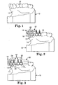
- Fig. 1 is an illustration of an example of a model or replica arch 10 of a patient's upper dental arch.
- the replica arch 10 includes a number of replica teeth 12 as well as adjacent portions of replica soft tissue 14 that are similar in shape to the patient's soft tissue or "gums".
- the replica arch 10 includes replicas of all of the teeth in the patient's upper (or lower) arch. If the impression is accurately taken and the replica dental arch 10 is carefully prepared, the replica teeth 12 and replica soft tissue 14 will have a configuration and orientation that are identical to the configuration and orientation of the corresponding teeth and soft tissue of the orthodontic patient.
- the replica arch 10 can be prepared by any one of a number of suitable known methods.
- the replica arch 10 may be prepared by first taking an impression of the patient's upper dental arch, taking care to avoid undue distortion.
- an alginate impression material is used such as Unijel-II brand alginate impression material from 3M Unitek.
- a hydrocolloid or a vinyl polysiloxane impression material may be used, such as Imprint brand vinyl polysiloxane impression from 3M.
- the replica arch 10 is made from each impression using, for example, a material such as plaster of Paris.
- the replica arch is substantially free of voids. If voids are present, the voids can be filled with a small, additional quantity of suitable material such as plaster of Paris.
- the replica arch 10 may be prepared by generating digital information defining the shape of the patient's upper dental arch, and then using the digital information to create a replica.
- the digital information may be created by the methods set out in PCT application no. WO 97/03622.
- WO 97/03622 describes a method of generating digital information of a patient's dental arches by making an impression of the patient's arches, and then removing a layer from the impression (or alternatively removing a layer from a model made from the impression) to obtain a flat surface; a video camera or other device is then used to collect digital data of the flat surface and the method is repeated; finally, the data is combined to provide a data set representative of the configuration of the patient's dental arches.
- the digital information may be generated electromechanically (e.g., stylus scanning), by laser scanning, by photogammetry, by sonic ranging, by digital video scanning or magnetically.
- Examples of devices for generating the information are described in an article by Rekow entitled “Computer Aided Design and Manufacture in Dentistry: A Review of the State of the Art", from the Journal of Prosthetic Dentistry, Vol. 58, page 512 (1987) which is expressly incorporated by reference herein.
- Other examples are described in U.S. Patent Nos.
- a layer of separating medium is applied to the replica arch 10 if desired.
- a thin layer of separating medium such as Liquid Foil brand sealing solution from 3M or Al-Cote brand separating medium from Dentsply is applied to the replica arch 10 and allowed to dry.
- a pencil mark may be made across the labial surface of each replica tooth 12 with the assistance of a height gauge such as a Boone bracket positioning gauge from 3M Unitek (Catalog No. 807-002).
- the pencil line is drawn across the labial surface of each replica tooth 12 in a mesial-distal direction, preferably as a locator guide for ultimate placement of the archwire slot of each orthodontic appliance on the patient's teeth.
- a pencil line may also be drawn across the labial surface of each replica tooth 12 in a generally occlusal-gingival direction to mark the central long axis of the tooth 12.
- the distance of the mesial-distal pencil line from the occlusal edge of the replica tooth 12 may vary in accordance with the treatment technique employed by the practitioner and the type of orthodontic appliance to be used by the practitioner.
- the distance of the pencil line from the occlusal edge of the replica teeth 12 may also vary in accordance with the type of tooth.
- the distance of the pencil mark from the occlusal edge of replica anterior teeth may be less than the distance of the pencil mark from the occlusal edge of replica cuspid and bicuspid teeth.
- Other types of gauges may also be used, such as the Dougherty bracket positioning gauge from 3M Unitek.
- a fixture component 16 is temporarily secured to each replica tooth 12 that is to be bonded using a transfer tray.
- a fixture component 16 has been secured to each replica tooth 12 except for replica molar teeth.
- Each fixture component 16 includes an orthodontic appliance analog 18 and a fixture arm 20 that is connected to each appliance analog 18.
- An adhesive such as 3M Unitek Laboratory Adhesive for Indirect Bonding (catalog no. 704-050) can be used to temporarily bond the appliance analog 18 to the replica tooth 12.
- a mechanical coupling or a holding fixture can be provided to releasably connect each appliance analog 18 to the corresponding replica tooth 12 during the subsequent steps of making the tray as described below.
- Each fixture arm 20 has a generally L-shaped configuration in side view, with a first portion that extends in an occlusal direction from the associated appliance analog 18 and a second portion that extends in a lingual direction from the occlusal end of the first portion. Both the first portion and the second portion of the fixture arm 20 are preferably spaced from the buccolabial and occlusal sides respectively of the associated replica tooth 12 when the fixture component 16 is secured to the replica tooth 12.
- the fixture arm 20 preferably has a non-circular cross-sectional shape.
- the fixture arm has a generally "T"-shaped configuration.
- Other cross-sectional configurations may also be employed, such as rectangular, "X"-shaped, "L”-shaped and the like.
- the appliance analog 18 has a base facing the associated replica tooth 12 that is larger in a mesial-distal direction (i.e., in a direction extending along the length of the dental arch) than the overall mesial-distal dimension of the base of the orthodontic appliance that is ultimately to be received on the corresponding tooth of the patient.
- the appliance analog 18 has a base that preferably is larger in an occlusal-gingival direction than the overall occlusal-gingival dimension of the same appliance.
- the fixture components 16 are made of a material suitable for numerous re-uses, such as hard tool steel or the like.
- the appliance analogs 18 have scribe marks, paint markings, indicia or other features to facilitate aligning the appliance analogs 18 with the mesial-distal and occlusal-gingival pencil marks previously made on the labial surface of each corresponding replica tooth 12. If, for example, the fixture components 16 are placed on the replica teeth 12 by hand, the fixture components 16 can be shifted slightly as needed after initial placement on the replica teeth 12 in order to bring such scribe marks or other indicia into precise alignment with the pencil marks on the replica teeth 12.
- the fixture components 16 may include tabs or gauges intended for contact or visual alignment with the occlusal edge of replica teeth 12 and oriented such that the appliance analog 18 is properly positioned on the replica tooth 12 in an occlusal-gingival direction when the tab is brought into contact or alignment with the occlusal edge of the same replica tooth.
- other types of placement devices may be used to position the analogs 18 on the replica teeth 12.
- hand-held devices that releasably grasp the analogs 18 can be employed, such as the devices described in U.S. Patent Nos. 4,455,137 and 4,850,864.
- those devices include gauges or jigs to position the analogs 18 on the replica teeth 12 at precise locations.
- bond placement devices useful in indirect bonding procedures such as the devices described in U.S. Patent No. 4,812,118 may be used.
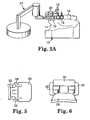
- an automated device such as a computer controlled robotic arm 21 as shown in Fig. 2a may be used for precise placement of each fixture component 16 on the associated replica tooth 12.
- software can be used to determine placement of the appliance analogs 18 and the use of pencil marks on the replica teeth 12 for alignment of the appliance analogs 18 may be omitted.
- a computer may be used to calculate an idealized position for each orthodontic appliance on the patient's teeth, and that information can then be used in a set of instructions to control movement of the robotic arm 21 such that the appliance analog 18 is placed on the corresponding, selected location of the associated replica tooth 12.
- a series of robotic arms may be used to releasably connect the fixture components 16 to corresponding replica teeth 12 during the steps of making a tray as described below.
- a quantity of matrix material is applied to the replica dental arch 10 and a portion of the fixture components 16.
- the matrix material is applied to the replica dental arch 10 and the lingually-extending second portion of the fixture arm 20, but is preferably not applied over the first portion of the arms 20 or over the appliance analogs 18.
- Fig. 3 is an illustration of matrix material that has been applied to the replica teeth 12 that have received a fixture component 16, as well as an adjacent replica molar tooth. The matrix material is then hardened or allowed to harden to form a transfer tray 22.
- suitable matrix materials include materials that are liquid or semi-liquid and subsequently harden, as well as sheet materials that are softened and then hardened.
- two layers of matrix materials may be utilized: a first layer of a liquid material that provides precise replication of the underlying surfaces, followed by a second layer of a material that has a semi-liquid or putty consistency.
- the matrix material may comprise two or more layers, where the resulting transfer tray 22 has an outer layer that is more rigid than an inner layer.
- the outer layer provides rigidity to the transfer tray 22, while the more flexible inner layer facilitates subsequent removal of the transfer tray 22 from the replica dental arch 10, particularly when the transfer tray 22 includes portions to be received in undercut regions of the patient's dental arch.
- the transfer tray 22 includes a generally "U"-shaped channel that extends along the length of the replica dental arch 10.
- the tray 22 includes a lingual section, a buccolabial section and an occlusal section interconnecting the lingual section and the buccolabial section.
- both the lingual section and the buccolabial section extend in a gingival direction a distance sufficient to pass over at least some of the interproximal areas next to the replica soft tissue. Those areas often include undercut regions and protruding regions that subsequently serve to securely couple the transfer tray 22 to the patient's dental arch.
- the occlusal section 24 projects in an occlusal direction from the occlusal edge of the replica teeth 12.
- the second portion of the fixture arm 20 i.e., the portion that extends in a labial-lingual direction
- the regions of the occlusal section 24 that receive the second portion of the fixture arms 20 is made of relatively rigid material.
- the buccolabial section of the transfer tray 22 includes portions 26 (Fig. 3) that extend along mesial and distal sides of the appliance analogs 18.
- the mesial and distal portions 26 abut the mesial and distal sides of the appliance analogs 18, and extend in a gingival direction along at least a majority of the length of the mesial and distal sides of the appliance analogs 18.
- at least some of the mesial and distal portions 26 may optionally extend beyond the gingival side of adjacent appliance analogs 18 in a gingival direction.
- the transfer tray 22 as well as the fixture components 16 are removed from the replica dental arch 10.
- the fixture components 16 are detached from the transfer tray 22 before the transfer tray 22 is separated from the replica arch 10.
- the fixture components 16 are released if desired from the transfer tray 22 by sliding the second portion of the fixture arms 20 in a buccolabial direction until the arms 20 are removed from the passageways that were formed by embedding the arms 20 in the matrix material.
- the fixture arms 20 may be made of or coated with a low-friction, lubricous and/or release material such as fluoropolymers in order to facilitate sliding movement of the fixture components 16 in the passageways.
- a suitable lubricating material that is available as an aerosol and may be sprayed onto the fixture arms 20 is MS-122 Fluorocarbon Release Agent Dry Lubricant from Miller-Stephenson.
- the transfer tray 22 is trimmed as needed to remove excess material.
- the transfer tray 22 is cut into two sections corresponding to each quadrant of the patient's upper dental arch in order to facilitate the subsequent steps as described below.
- the transfer tray 22 may be cut into a greater number of sections, such that each resulting section corresponds to less than a quadrant of the patient's upper dental arch.
- the transfer tray 22 may optionally be cut into small sections that correspond to only a single tooth if so desired.
- each fixture component 16 is replaced with an orthodontic appliance 28 and a carrier or carrier arm 30, two examples of which are shown in Fig. 4.
- the fixture components 16 may be replaced with the appliances 28 in a manual procedure or in an automated procedure using robotic arms or the like.
- the carrier arm 30 is releasably connected to the appliance 28 by a pair of flexible stirrups 32 that are shown in more detail in Figs. 5 and 6.
- the stirrups 32 snap into notches behind occlusal and gingival tiewings of the appliance 28 in order to releasably connect the appliance 28 to the carrier arm 30.
- the carrier arm 30 also includes a slot segment (not shown) that is received in an archwire slot of the appliance 28 when the appliance 28 is connected to the carrier arm 30.
- the slot segment serves to stabilize the appliance 28 and hinder undue movement of the latter relative to the carrier arm 30.
- the slot segment has an interference fit with the archwire slot, or has movable portions that expand to tightly fit within the archwire slot so that the stirrups 32 may be omitted.
- the carrier arm 30 may be provided with flexible stirrups of the type described in U.S. Patent No. 5,429,229.
- the carrier arm 30 may have movable jaws that releasably clamp against the mesial and distal sides of the appliance 28.
- a substance having a gummy consistency and/or exhibiting adhesive characteristics may be utilized as a temporary coupling.
- the carrier arm 30 and the orthodontic appliance 28 may be initially integrally joined together by a frangible web that is fractured (e.g., by bending or cutting) after the appliance 28 is bonded to the patient's tooth.
- the transfer tray 22 is then placed over the patient's tooth structure that corresponds to the replica teeth 12.
- the transfer tray 22 has been placed over the patient's upper dental arch 36, including teeth 38.
- the carrier arms 30 are retracted sufficiently in the passageways 40 to ensure that any adhesive on the base of the appliance 28 is located buccolabially of the buccolabial side of the tray channel. As a result, the adhesive will not smear or otherwise contact the patient's tooth surface during placement of the transfer tray 22, a distinct advantage in contrast to many conventional indirect bonding methods.
- the undisturbed adhesive on the base of the appliances 28 can be brought into contact with the patient's teeth at any convenient time upon movement of the carrier arms 30 in a lingual direction.
- the transfer tray 22 is releasably received on the patient's upper dental arch 36 in secure fashion such that the transfer tray 22 is relatively immobile relative to the patient's teeth 38.
- the undercut regions and protruding regions of the transfer tray 22 as described above facilitate the immobilization of the transfer tray 22 on the upper dental arch 36.
- the mesial and distal portions 26 of the transfer tray 22 engage underlying tooth structure adjacent the appliances 28 to further help immobilize the transfer tray 22.
- a suitable orthodontic bonding adhesive is applied to the base of each orthodontic appliance 28.
- suitable bonding adhesives include light-curable adhesives such as Transbond XT or Transbond LR adhesives from 3M Unitek.
- two-component chemical curing adhesives that begin to cure when mixed together may also be used, such as Concise brand adhesive from 3M. If a two-component adhesive is used, the components may be mixed together and then applied to the appliances 28. Alternatively, if the appliance base closely matches the configuration of the tooth surface, one component of a two-component adhesive may be applied to the tooth surface and the other component applied to the appliance 28, such that the components are mixed when the appliance 28 is pressed against the tooth 38.
- Fig. 4 also shows passageways 40 that extend through the occlusal section 24 of the transfer tray 22.
- the passageways 40 were formed by the second portions of the fixture arms 20 once embedded in the matrix material as described above, and remain in the occlusal section 24 after separation of the fixture arms 20 from the transfer tray 22.
- the carrier arms 30 have a lingually extending occlusal portion that has a cross-sectional configuration identical to the cross-sectional configuration of the second portion of the corresponding fixture arm 20, so that the carrier arm 30 is slidable in a longitudinal direction in the passageway 40 but is substantially prevented from movement in a lateral direction (i.e., movement in a mesial-distal direction or an occlusal-gingival direction).
- the carrier arms 30 and the associated appliances 20 are connected to the transfer tray 22 before the transfer tray 22 is placed over the patient's upper dental arch 36.
- the transfer tray 22 may be first placed on the patient's dental arch 36 and subsequently each of the carrier arms 30 along with the associated appliance 28 is connected to the tray 22 by inserting the carrier arms 30 into the respective passageways 40.
- the appliances 28 are bonded to the buccolabial surfaces of the patient's teeth 38 by sliding the carrier arms 30 in a lingual direction, preferably using finger pressure.
- finger pressure provides tactile feedback, so that the practitioner can determine when the appliance 28 has been seated with sufficient force against the surface of the patient's tooth 38 to create a satisfactory bond.
- the tactile feedback also helps the practitioner confirm that the adhesive has a proper viscosity and is present in sufficient quantity.
- a mechanical or pneumatic device may be employed (such as a piston and cylinder assembly or solenoid assembly) to move the arms 30 in lingual (and also optionally in labial) directions.
- a small quantity of adhesive is extruded from all four sides of the appliance 28 as the appliance is pressed against the tooth surface.
- the likelihood of the presence of any small voids or recesses in the adhesive is substantially reduced. It is preferred to avoid recesses and voids in the adhesive, since such recesses and voids might otherwise reduce the strength of the bond between the appliance 28 and the associated tooth 38.
- Recesses and voids may also provide a location that can collect food or other debris that can result in the formation of caries.
- the base of the orthodontic appliance 28 preferably has overall mesial-distal and occlusal-gingival dimensions that are less than the corresponding mesial-distal and occlusal-gingival overall dimensions of the appliance analog 18.
- the transfer tray 22 including the mesial and distal portions 26 are spaced from adjacent sides of the appliance 28 when the appliance 28 is pushed against the outer surface of the tooth 38 for bonding.
- the spacing between the appliance 28 and the transfer tray 22 provides an area where adhesive can be freely expressed from the base of the appliance 28 as the latter is urged toward the tooth 38, and allows the practitioner to visually confirm that sufficient adhesive is present to provide at least some extrusion of adhesive from at least one side of the appliance 28.
- the space between the appliance 28 and adjacent portions of the tray 22 facilitates clean-up of adhesive extruded from the area between base of the appliance 28 and the tooth 38.
- the space conveniently allows a dental explorer or other tool to be moved along all sides of the appliance 28 in order to remove excess adhesive from the tooth surface adjacent edges of the appliance 28.
- the transfer tray 22 is transparent or translucent to actinic radiation in order to facilitate directing the light toward the adhesive.
- the above-mentioned space between the appliance 28 and the transfer tray 22 also helps the light reach the adhesive.
- the appliances 28 have a base that has a coating of light-curable adhesive applied by the manufacturer.
- adhesive pre-coated appliances are described, for example, in U.S. Patent Nos. 5,015,180, 5,172,809, 5,354,199 and 5,429,299.
- the appliances 28 may be any bondable orthodontic device such as brackets, buccal tubes and the like.
- the appliances 28 may be made of any suitable material such as metal (e.g., stainless steel), ceramic (e.g., translucent polycrystalline alumina or transparent single crystal alumina) or plastic (e.g., translucent polycarbonate).
- suitable appliances 28 include essentially all commercially available direct-bond brackets and buccal tubes as well as various appliances known in the literature including the patent literature.
- the transfer tray 22 is made in a dental laboratory or by an orthodontic appliance manufacturer after receiving an impression or an electronic data file representative of the patient's dental arches. Consequently, the dental laboratory or the manufacturer can re-use the fixture components 16 a number of times.
- the appliances 28, carrier arms 30 and transfer tray 22 are assembled and preferably shipped to the orthodontist as single units, ready for use with minimal further preparation at the orthodontist's office.
- the carrier arms 30 are made of a relatively inexpensive material such as plastic that can be disposed of after a single use.
- the fixture arms 20 also serve as the carrier arms 30.
- the fixture arm 20 are releasably connected to the appliance analog 18, so that the arms 20 can be subsequently releasably coupled to an appliance such as the appliances 28.
- the releasably couplings as described above in various forms in connection with the carrier arms 30 may be used to detachably connected the appliance analogs 18 to the fixture arms 20.
- each fixture arm 20 may have a somewhat different cross-sectional shape, and in that instance the carrier arms 30 as well as the passageway associated with each fixture arm 20 would have a similar, corresponding cross-sectional shape.
- one of the fixture arms 20 may have a rectangular cross-sectional shape
- another arm 20 may have a generally "T"-shaped configuration (such as shown in Fig. 4) while other fixture arms 20 may have a "X"-shaped configuration or an oval-shaped configuration in cross-sectional view.
- Such different cross-sectional shapes when employed in connection with a single transfer tray 22, function as keys and mating keyways to help ensure that each passageway 40 receives the correct carrier arm 30. As a result, the practitioner is assured that the correct appliance 28 is ultimately bonded to the correct corresponding tooth 38.
- a computer may be used to assist in calculating the proper orientation of the appliances 28 on the respective teeth 38 as may be required to move the teeth 38 to desired positions.
- a method is especially useful when digital information has been created as described above defining the shape and location of the maloccluded teeth with respect to the patient's jaw.
- the methods described in U.S. Patent No. 5,011,405 can be used to calculate the proper position of the appliances 28 on the teeth 38.
- Such a method can optionally include the steps of generating a mathematical model of the maloccluded teeth as positioned on the jaw from the digitized information, and calculating the finished position in the jaw to which the maloccluded teeth are to be moved from the digitized information.
- the digital information can be used if desired to make a custom appliance or to modify standard appliances to facilitate treatment. For example, brackets with certain patent-specific characteristics such as a certain torque and/or angulation can be made. Moreover, the digital information may be used to form an archwire for use with the appliances.
- the automated, robotic equipment described above may be used in carrying out such a method.
- the digital information defining the shape and the location of the maloccluded teeth with respect to the patient's jaw as described above may be utilized to make a transfer tray (such as the transfer tray 22) or tray section without making a physical replica dental arch 10.
- the digitized information can be used, for example, in association with stereolithographic apparatus to custom-make the transfer tray 22 with a channel complemental to the shape of the patient's dental arch as determined by digital data representative of the patient's arch or arch section or by a virtual replica arch or arch section created by a computer.
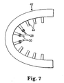
- a master fixture 42 as shown in Fig. 7 could be provided to support individual fixture components (such as fixture components 16) or appliances in a desired orientation as determined by a computer program while the transfer tray 22 is made.
- the use of appliance analogs is optional, and alternatively the carrier arms 30 releasably supporting the appliances 28 can be embedded in the transfer tray 22 as the transfer tray 22 is made.
- the master fixture 42 includes an array of movable robotic arms 44, each holding one of the appliances or appliance analogs at a certain orientation relative to the remaining appliances or appliance analogs in accordance with the digital data and according to software that determines optimal orientations for efficient orthodontic treatment.
- digital data defining the shape and the location of the maloccluded teeth with respect to the patient's jaw may be used to make a transfer tray (such as tray 22) or tray section without making a physical replica dental arch 10 and also without embedding either fixture arms (such as arms 20) or carrier arms (such as arms 30) in the matrix material as the tray or tray section is made.
- stereolithographic apparatus is used to custom-make the tray or tray section and to also make passageways (such as passageways 40).
- the passageways are cut in the tray or tray section in a subsequent step using, for example, a machining process. Once the tray or tray section is made, the carrier arms are inserted into the passageways, either by hand or in an automated process.
- the transfer tray need not be fully match all of the patient's underlying tooth structure.
- the tray may contact the tooth structure only at certain, spaced-apart regions. Such partial contact may be satisfactory so long as the regions are of sufficient size and configuration to ensure that the practitioner will be able to place the tray in its proper orientation in the oral cavity without undue effort.
- appliances and the archwires may be custom made using in part the digital information described above, or may be selected from a set of "standard" appliances and archwires.
- an automated selection of optimal appliances and archwires is made from commercially available, off-the shelf products.
- the carrier arm 30 is moved in a buccolabial direction to disengage the appliance 28.
- the stirrups 32 deflect outwardly and the slot segment (if present) disengages the archwire slot of the appliance 28 in order to allow the appliance 28 to detach from the carrier arm 30.
- the carrier arms 30 can be withdrawn and detached from the transfer tray 22 before removal of the transfer tray 22 from the patient's oral cavity.
- the carrier arms 30 can remain connected to the transfer tray 22 while the latter is removed from the oral cavity.
Landscapes
- Health & Medical Sciences (AREA)
- Oral & Maxillofacial Surgery (AREA)
- Dentistry (AREA)
- Epidemiology (AREA)
- Life Sciences & Earth Sciences (AREA)
- Animal Behavior & Ethology (AREA)
- General Health & Medical Sciences (AREA)
- Public Health (AREA)
- Veterinary Medicine (AREA)
- Dental Tools And Instruments Or Auxiliary Dental Instruments (AREA)
Claims (32)
- Procédé pour relier un appareil orthodontique à une dent, ledit procédé comportant les étapes qui consistent à :créer une réplique de la structure d'une dent du patient,relier de manière libérable au moins un composant de fixation à la réplique, chaque composant de fixation comprenant un analogue de l'appareil orthodontique et un bras relié à l'analogue de l'appareil, chaque analogue d'appareil étant placé sur la réplique en un emplacement qui correspond à l'emplacement de la structure de la dent du patient où un appareil orthodontique doit être placé,réaliser un réceptacle de transfert en plaçant un matériau de matrice sur au moins une partie de la réplique,détacher le réceptacle de transfert de la réplique,remplacer chaque analogue d'appareil par un appareil orthodontique,appliquer un adhésif orthodontique sur la structure de la dent du patient et/ou sur chaque appareil orthodontique,placer le réceptacle de transfert sur la structure de la dent etdéplacer chaque bras par rapport au réceptacle de transfert de manière à amener chaque appareil orthodontique au contact de la structure de la dent du patient.
- Procédé selon la revendication 1, dans lequel l'étape de fabrication d'un réceptacle de transfert comprend l'étape qui consiste à placer du matériau de matrice sur au moins une partie d'au moins un bras.
- Procédé selon la revendication 2, dans lequel chaque bras présente en section transversale une configuration différente de la configuration de la section transversale des bras adjacents.
- Procédé selon la revendication 1, qui comprend l'étape qui consiste à doter chaque analogue d'appareil d'une base dont la dimension mésiodistale globale est plus grande que la dimension mésiodistale globale de l'appareil orthodontique correspondant.
- Procédé selon la revendication 1, dans lequel l'étape qui consiste à relier au moins un composant de fixation à la réplique comprend l'étape qui consiste à prévoir un bras de robot pour placer chaque composant de fixation sur la réplique.
- Procédé selon la revendication 1, dans lequel l'étape qui consiste à créer une réplique de la structure de la dent du patient est réalisée en utilisant des données numériques.
- Procédé selon la revendication 1, dans lequel l'étape qui consiste à réaliser le réceptacle de transfert comprend l'étape qui consiste à réaliser des parties qui s'étendent le long du côté mésial et du côté distal de l'analogue d'appareil.
- Procédé selon la revendication 7, dans lequel l'étape qui consiste à détacher le réceptacle de transfert de la réplique comprend l'étape qui consiste à détacher chaque analogue d'appareil de la réplique.
- Procédé selon la revendication 1, qui comprend l'étape qui consiste à remplacer le bras relié à l'analogue d'appareil par un support relié de manière libérable à l'appareil.
- Procédé selon la revendication 9, dans lequel le support est relié de manière libérable à l'appareil par des étriers qui engagent de manière complémentaire les ailes de liaison de l'appareil.
- Procédé pour relier un appareil orthodontique à une dent, ledit procédé comportant les étapes qui consistent à :créer une réplique de la structure d'une dent du patient,relier de manière libérable au moins un composant de fixation à la réplique, chaque composant de fixation étant placé sur la réplique en un emplacement qui correspond à l'emplacement de la structure de la dent du patient où un appareil orthodontique doit être placé,réaliser un réceptacle de transfert en plaçant du matériau de matrice sur au moins une partie de la réplique ainsi que sur au moins une partie d'au moins un composant de fixation,détacher le réceptacle de transfert de la réplique,détacher au moins une partie d'au moins un composant de fixation du réceptacle de transfert,relier au moins un appareil orthodontique au réceptacle de transfert en un ou plusieurs emplacements respectifs qui correspondent aux emplacements précédents d'au moins l'un des composants ou parties de composants de fixation détachés,appliquer un adhésif orthodontique sur la structure de la dent du patient et/ou sur chaque appareil orthodontique à relier etplacer le réceptacle de transfert et chaque appareil orthodontique sur la structure de dent correspondante du patient pour relier chaque appareil orthodontique à la structure de la dent.
- Procédé selon la revendication 11, dans lequel chaque composant de fixation comporte un analogue d'appareil et un bras de fixation qui déborde de l'analogue d'appareil et dans lequel l'étape qui consiste à réaliser un réceptacle de transfert comprend l'étape qui consiste à placer le matériau de matrice sur au moins une partie d'au moins un bras de fixation.
- Procédé selon la revendication 12, dans lequel l'étape qui consiste à relier au moins un appareil orthodontique au réceptacle de transfert comporte l'étape qui consiste à prévoir un bras de support fixé de manière libérable à l'appareil et relié au réceptacle de transfert.
- Procédé selon la revendication 13 qui comprend l'étape qui consiste à faire coulisser chaque bras de support par rapport au réceptacle de transfert après avoir placé le réceptacle de transfert sur la structure de la dent de manière à amener l'appareil correspondant au contact de la structure de la dent.
- Procédé selon la revendication 13, dans lequel chaque bras de support comprend au moins un étrier flexible d'accouplement à une aile de liaison de l'appareil.
- Procédé selon la revendication 12, qui comprend l'étape qui consiste à doter chaque analogue d'appareil d'une base plus grande que la base de l'appareil correspondant dans la direction mésiodistale.
- Procédé selon la revendication 11, dans lequel l'étape qui consiste à détacher le réceptacle de transfert de la réplique comprend l'étape qui consiste à détacher chaque composant de fixation de la réplique.
- Procédé selon la revendication 11, dans lequel l'étape qui consiste à relier de manière libérable au moins un composant de fixation à la réplique comprend l'étape qui consiste à prévoir un bras de robot pour placer chaque composant de fixation sur la réplique.
- Procédé selon la revendication 11, dans lequel l'étape qui consiste à créer une réplique de la structure d'une dent du patient est réalisée en recourant à des données numériques.
- Procédé selon la revendication 19, qui comprend l'étape qui consiste à réaliser au moins en partie l'appareil orthodontique en utilisant en partie les données numériques.
- Procédé selon la revendication 20, qui comprend en outre l'étape qui consiste à réaliser au moins en partie un fil d'arc en utilisant en partie les données numériques.
- Procédé de réalisation d'un réceptacle de transfert pour un patient d'orthodontie, ledit procédé comportant les étapes qui consistent à :créer une réplique de la structure d'une dent du patient,relier de manière libérable au moins un composant de fixation à la réplique, chaque composant de fixation comprenant un analogue d'appareil orthodontique et un bras relié à l'analogue d'appareil, chaque analogue d'appareil étant placé sur la réplique en un emplacement qui correspond à l'emplacement de la structure de la dent du patient où un appareil orthodontique doit être placé, placer du matériau de matrice sur au moins une partie de la réplique ainsi que sur au moins une partie du bras d'au moins un composant de fixation,détacher le réceptacle de transfert de la réplique etremplacer chaque analogue d'appareil par un appareil orthodontique.
- Procédé selon la revendication 22, dans lequel chaque bras a en section transversale une configuration différente de la configuration de la section transversale des bras adjacents.
- Procédé selon la revendication 21, qui comprend l'étape qui consiste à doter chaque analogue d'appareil d'une base dont la dimension mésiodistale globale est plus grande que la dimension mésiodistale globale de l'appareil orthodontique correspondant.
- Procédé selon la revendication 21, dans lequel l'étape qui consiste à relier au moins un composant de fixation à la réplique comprend l'étape qui consiste à prévoir un bras de robot pour placer chaque composant de fixation sur la réplique.
- Procédé selon la revendication 21, dans lequel l'étape qui consiste à créer une réplique de la structure de la dent du patient est réalisée en utilisant des données numériques.
- Procédé selon la revendication 26, qui comprend l'étape qui consiste à fabriquer au moins en partie l'appareil orthodontique en utilisant en partie les données numériques.
- Procédé selon la revendication 26, qui comprend l'étape qui consiste à fabriquer au moins en partie un fil d'arc en utilisant en partie les données numériques.
- Procédé selon la revendication 22, dans lequel l'étape qui consiste à réaliser le réceptacle de transfert comprend l'étape qui consiste à réaliser des parties qui s'étendent le long du côté mésial et du côté distal de l'analogue d'appareil.
- Procédé selon la revendication 22, dans lequel l'étape qui consiste à détacher le réceptacle de transfert de la réplique comprend l'étape qui consiste à détacher chaque analogue d'appareil de la réplique.
- Procédé selon la revendication 22, qui comprend l'étape qui consiste à remplacer le bras relié à l'analogue d'appareil par un support relié de manière libérable à l'appareil.
- Procédé selon la revendication 22, dans lequel le support est relié de manière libérable à l'appareil par des étriers qui engagent de manière complémentaire les ailes de liaison de l'appareil.
Priority Applications (1)
| Application Number | Priority Date | Filing Date | Title |
|---|---|---|---|
| EP06016336A EP1769772A3 (fr) | 1998-12-18 | 1999-05-03 | Prodédé er appareil permettant de placer et de fixer avec précision des appareils orthodontiques |
Applications Claiming Priority (3)
| Application Number | Priority Date | Filing Date | Title |
|---|---|---|---|
| US09/216,310 US6123544A (en) | 1998-12-18 | 1998-12-18 | Method and apparatus for precise bond placement of orthodontic appliances |
| US216310 | 1998-12-18 | ||
| PCT/US1999/009649 WO2000036989A1 (fr) | 1998-12-18 | 1999-05-03 | Procede et appareil permettant de placer et de fixer avec precision des appareils orthodontiques |
Related Child Applications (1)
| Application Number | Title | Priority Date | Filing Date |
|---|---|---|---|
| EP06016336A Division EP1769772A3 (fr) | 1998-12-18 | 1999-05-03 | Prodédé er appareil permettant de placer et de fixer avec précision des appareils orthodontiques |
Publications (2)
| Publication Number | Publication Date |
|---|---|
| EP1139903A1 EP1139903A1 (fr) | 2001-10-10 |
| EP1139903B1 true EP1139903B1 (fr) | 2006-10-11 |
Family
ID=22806564
Family Applications (2)
| Application Number | Title | Priority Date | Filing Date |
|---|---|---|---|
| EP06016336A Withdrawn EP1769772A3 (fr) | 1998-12-18 | 1999-05-03 | Prodédé er appareil permettant de placer et de fixer avec précision des appareils orthodontiques |
| EP99921614A Expired - Lifetime EP1139903B1 (fr) | 1998-12-18 | 1999-05-03 | Procede et appareil permettant de placer et de fixer avec precision des appareils orthodontiques |
Family Applications Before (1)
| Application Number | Title | Priority Date | Filing Date |
|---|---|---|---|
| EP06016336A Withdrawn EP1769772A3 (fr) | 1998-12-18 | 1999-05-03 | Prodédé er appareil permettant de placer et de fixer avec précision des appareils orthodontiques |
Country Status (6)
| Country | Link |
|---|---|
| US (1) | US6123544A (fr) |
| EP (2) | EP1769772A3 (fr) |
| JP (1) | JP4230667B2 (fr) |
| AU (1) | AU3878099A (fr) |
| DE (1) | DE69933580T2 (fr) |
| WO (1) | WO2000036989A1 (fr) |
Cited By (1)
| Publication number | Priority date | Publication date | Assignee | Title |
|---|---|---|---|---|
| DE102014106151B4 (de) * | 2013-05-02 | 2017-08-31 | Ezbond Co., Ltd. | Methode zur Positionierung von kieferorthopädischen Spangen |
Families Citing this family (299)
| Publication number | Priority date | Publication date | Assignee | Title |
|---|---|---|---|---|
| US6450807B1 (en) | 1997-06-20 | 2002-09-17 | Align Technology, Inc. | System and method for positioning teeth |
| US7063532B1 (en) | 1997-06-20 | 2006-06-20 | Align Technology, Inc. | Subdividing a digital dentition model |
| AU744385B2 (en) | 1997-06-20 | 2002-02-21 | Align Technology, Inc. | Method and system for incrementally moving teeth |
| US8496474B2 (en) | 1997-06-20 | 2013-07-30 | Align Technology, Inc. | Computer automated development of an orthodontic treatment plan and appliance |
| US5975893A (en) | 1997-06-20 | 1999-11-02 | Align Technology, Inc. | Method and system for incrementally moving teeth |
| IL121872A (en) * | 1997-09-30 | 2002-12-01 | Cadent Ltd | Position of an orthodontic element on a tooth surface |
| US6334772B1 (en) | 1997-09-30 | 2002-01-01 | Cadent Ltd. | Placing an orthodontic element on a tooth surface |
| US7507088B2 (en) | 1997-09-30 | 2009-03-24 | Cadent Ltd. | Method for comparing orthodontic element placement |
| IL122807A0 (en) | 1997-12-30 | 1998-08-16 | Cadent Ltd | Virtual orthodontic treatment |
| IL125659A (en) | 1998-08-05 | 2002-09-12 | Cadent Ltd | Method and device for three-dimensional simulation of a structure |
| US6802713B1 (en) | 1998-10-08 | 2004-10-12 | Align Technology, Inc. | Defining tooth-moving appliances computationally |
| US11026768B2 (en) | 1998-10-08 | 2021-06-08 | Align Technology, Inc. | Dental appliance reinforcement |
| WO2000019929A1 (fr) | 1998-10-08 | 2000-04-13 | Align Technology, Inc. | Developpement informatique automatise d'un plan de traitement orthodontique et d'un appareil prevu a cet effet |
| US6572372B1 (en) * | 2000-04-25 | 2003-06-03 | Align Technology, Inc. | Embedded features and methods of a dental appliance |
| US6406292B1 (en) | 1999-05-13 | 2002-06-18 | Align Technology, Inc. | System for determining final position of teeth |
| US8821158B1 (en) | 1999-10-14 | 2014-09-02 | Geodigm Corporation | Method and apparatus for matching digital three-dimensional dental models with digital three-dimensional cranio-facial CAT scan records |
| US6554613B1 (en) * | 2000-04-19 | 2003-04-29 | Ora Metrix, Inc. | Method and apparatus for generating an orthodontic template that assists in placement of orthodontic apparatus |
| US6648640B2 (en) * | 1999-11-30 | 2003-11-18 | Ora Metrix, Inc. | Interactive orthodontic care system based on intra-oral scanning of teeth |
| US6447291B2 (en) | 1999-12-31 | 2002-09-10 | Joong Han Kim | Orthodontic jig for attaching orthodontic brackets |
| DE20023670U1 (de) * | 2000-02-08 | 2005-10-06 | Dental Consulting Mönkmeyer S.L. | Zahnsortiment und System zur Präparation von Zähnen |
| US6463344B1 (en) | 2000-02-17 | 2002-10-08 | Align Technology, Inc. | Efficient data representation of teeth model |
| US7904307B2 (en) | 2000-03-24 | 2011-03-08 | Align Technology, Inc. | Health-care e-commerce systems and methods |
| US20020188478A1 (en) | 2000-03-24 | 2002-12-12 | Joe Breeland | Health-care systems and methods |
| US6971873B2 (en) * | 2000-04-19 | 2005-12-06 | Orametrix, Inc. | Virtual bracket library and uses thereof in orthodontic treatment planning |
| US6454565B2 (en) | 2000-04-25 | 2002-09-24 | Align Technology, Inc. | Systems and methods for varying elastic modulus appliances |
| WO2001082192A1 (fr) | 2000-04-25 | 2001-11-01 | Align Technology, Inc. | Systeme et procede d'analyse en vue de traitements |
| US6386878B1 (en) | 2000-08-16 | 2002-05-14 | Align Technology, Inc. | Systems and methods for removing gingiva from teeth |
| US7040896B2 (en) | 2000-08-16 | 2006-05-09 | Align Technology, Inc. | Systems and methods for removing gingiva from computer tooth models |
| KR100379987B1 (ko) | 2000-08-25 | 2003-04-16 | 조재형 | 치열교정용 치아 브라켓의 정위 및 접착 보조장치 |
| US6497574B1 (en) | 2000-09-08 | 2002-12-24 | Align Technology, Inc. | Modified tooth positioning appliances and methods and systems for their manufacture |
| US6607382B1 (en) | 2000-09-21 | 2003-08-19 | Align Technology, Inc. | Methods and systems for concurrent tooth repositioning and substance delivery |
| US6726478B1 (en) | 2000-10-30 | 2004-04-27 | Align Technology, Inc. | Systems and methods for bite-setting teeth models |
| US6783360B2 (en) | 2000-12-13 | 2004-08-31 | Align Technology, Inc. | Systems and methods for positioning teeth |
| US7074038B1 (en) | 2000-12-29 | 2006-07-11 | Align Technology, Inc. | Methods and systems for treating teeth |
| KR200230655Y1 (ko) * | 2000-12-29 | 2001-07-03 | 경희문 | 치열교정용 간접접착 브라켓 포지셔너 |
| US7580846B2 (en) | 2001-01-09 | 2009-08-25 | Align Technology, Inc. | Method and system for distributing patient referrals |
| US7387511B2 (en) * | 2002-01-22 | 2008-06-17 | Geodigm Corporation | Method and apparatus using a scanned image for automatically placing bracket in pre-determined locations |
| US7347686B2 (en) * | 2002-01-22 | 2008-03-25 | Geodigm Corporation | Method and apparatus using a scanned image for marking bracket locations |
| WO2003075782A1 (fr) * | 2002-03-13 | 2003-09-18 | Christoph Von Mandach | Procede d'application de pieces de fixation orthodontiques |
| US6830450B2 (en) * | 2002-04-18 | 2004-12-14 | Align Technology, Inc. | Systems and methods for improved engagement between aligners and teeth |
| US20030220778A1 (en) * | 2002-04-29 | 2003-11-27 | Hultgren Bruce Willard | Method and apparatus for electronically simulating jaw function within electronic model images |
| US7716024B2 (en) * | 2002-04-29 | 2010-05-11 | Geodigm Corporation | Method and apparatus for electronically generating a color dental occlusion map within electronic model images |
| US7094053B2 (en) * | 2002-05-28 | 2006-08-22 | Ormco Corporation | Custom jig for placing orthodontic brackets and methods of making and using same |
| US7255558B2 (en) | 2002-06-18 | 2007-08-14 | Cadent, Ltd. | Dental imaging instrument having air stream auxiliary |
| EP1374795B1 (fr) * | 2002-06-20 | 2005-03-23 | Claus Dipl.-Ing. Schendell-Gröling | Dispositif d'aide à la mise en place d'un bracket orthodontique |
| US6979196B2 (en) * | 2002-06-21 | 2005-12-27 | Align Technology, Inc. | Systems and methods for automated bite-setting of tooth models |
| US7033327B2 (en) * | 2002-09-13 | 2006-04-25 | 3M Innovative Properties Company | Method of determining the long axis of an object |
| US6905337B1 (en) | 2002-09-17 | 2005-06-14 | Orametrix, Inc. | Tooth templates for bracket positioning and other uses |
| US7220124B2 (en) | 2002-10-03 | 2007-05-22 | Cadent Ltd. | Method for preparing a physical plaster model |
| US7695277B1 (en) | 2004-10-28 | 2010-04-13 | Rmo, Inc. | Orthodontic bracket with frangible cover mechanism |
| US7959437B2 (en) | 2002-10-29 | 2011-06-14 | Rmo, Inc. | Orthodontic appliance with encoded information formed in the base |
| US20040166462A1 (en) | 2003-02-26 | 2004-08-26 | Align Technology, Inc. | Systems and methods for fabricating a dental template |
| US20040166463A1 (en) * | 2003-02-26 | 2004-08-26 | Align Technology, Inc. | Systems and methods for combination treatments of dental patients |
| EP1610708B1 (fr) | 2003-04-03 | 2019-11-27 | Align Technology, Inc. | Procédé et système de fabrication d'une chape dentaire |
| US7020963B2 (en) * | 2003-05-02 | 2006-04-04 | 3M Innovative Properties Company | Method and apparatus for indirect bonding of orthodontic appliances |
| US7030383B2 (en) | 2003-08-04 | 2006-04-18 | Cadent Ltd. | Speckle reduction method and apparatus |
| US20050074717A1 (en) * | 2003-10-03 | 2005-04-07 | 3M Innovative Properties Company | Method and apparatus for bonding orthodontic appliances to teeth |
| US7137812B2 (en) * | 2003-10-03 | 2006-11-21 | 3M Innovative Properties Company | Apparatus for indirect bonding of orthodontic appliances and method of making the same |
| US20080076998A1 (en) * | 2003-12-01 | 2008-03-27 | Z-Tech (Canada) Inc. | Breast electrode array and method of analysis for detecting and diagnosing diseases |
| US7210929B2 (en) * | 2003-12-12 | 2007-05-01 | 3M Innovative Properties Company | Method of orienting an orthodontic appliance to a tooth |
| US8194067B2 (en) * | 2004-02-04 | 2012-06-05 | 3M Innovative Properties Company | Planar guides to visually aid orthodontic appliance placement within a three-dimensional (3D) environment |
| US7333874B2 (en) | 2004-02-24 | 2008-02-19 | Cadent Ltd. | Method and system for designing and producing dental prostheses and appliances |
| US9492245B2 (en) | 2004-02-27 | 2016-11-15 | Align Technology, Inc. | Method and system for providing dynamic orthodontic assessment and treatment profiles |
| US11298209B2 (en) | 2004-02-27 | 2022-04-12 | Align Technology, Inc. | Method and system for providing dynamic orthodontic assessment and treatment profiles |
| US7904308B2 (en) | 2006-04-18 | 2011-03-08 | Align Technology, Inc. | Method and system for providing indexing and cataloguing of orthodontic related treatment profiles and options |
| US8874452B2 (en) | 2004-02-27 | 2014-10-28 | Align Technology, Inc. | Method and system for providing dynamic orthodontic assessment and treatment profiles |
| ES2803973T3 (es) * | 2004-03-04 | 2021-02-01 | Align Technology Inc | Método implementado por ordenador de provisión de una representación digital de una plantilla ortodóntica para la colocación de un objeto en un diente de un paciente |
| US7702492B2 (en) | 2004-03-11 | 2010-04-20 | Geodigm Corporation | System and method for generating an electronic model for a dental impression having a common coordinate system |
| US7824346B2 (en) * | 2004-03-11 | 2010-11-02 | Geodigm Corporation | Determining condyle displacement utilizing electronic models of dental impressions having a common coordinate system |
| US7347688B2 (en) * | 2004-04-15 | 2008-03-25 | Cadent Ltd. | Dental targetting device and method |
| US20050244768A1 (en) * | 2004-04-28 | 2005-11-03 | Eldad Taub | Device and method for applying an abutment force between dental appliance and teeth |
| US8070486B2 (en) * | 2004-04-30 | 2011-12-06 | Lester Kuperman | Method and apparatus for indirect bonding of orthodontic appliances to teeth |
| US7153130B2 (en) * | 2004-06-10 | 2006-12-26 | 3M Innovative Properties Company | Orthodontic appliance with removable insert |
| EP1607064B1 (fr) | 2004-06-17 | 2008-09-03 | Cadent Ltd. | Procédé et appareil d'imagerie en couleurs d'une structure tridimensionnelle |
| US8517727B2 (en) * | 2004-07-30 | 2013-08-27 | 3M Innovative Properties Company | Automatic adjustment of an orthodontic bracket to a desired occlusal height within a three-dimensional (3D) environment |
| US8899976B2 (en) | 2004-09-24 | 2014-12-02 | Align Technology, Inc. | Release agent receptacle |
| US7291011B2 (en) * | 2004-10-06 | 2007-11-06 | 3M Innovative Properties Company | Placing orthodontic objects along an archwire within a three-dimensional (3D) environment |
| US7354268B2 (en) * | 2004-10-06 | 2008-04-08 | 3M Innovative Properties Company | Movement of orthodontic objects along a virtual archwire within a three-dimensional (3D) environment |
| US7168950B2 (en) | 2004-10-18 | 2007-01-30 | 3M Innovative Properties Company | Orthodontic methods and apparatus for applying a composition to a patient's teeth |
| US7309230B2 (en) | 2004-12-14 | 2007-12-18 | Align Technology, Inc. | Preventing interference between tooth models |
| US7869983B2 (en) * | 2004-11-17 | 2011-01-11 | 3M Innovative Properties Company | Computing final occlusion with respect to torque loss in a three-dimensional virtual orthodontic system |
| US7862336B2 (en) | 2004-11-26 | 2011-01-04 | Cadent Ltd. | Method and system for providing feedback data useful in prosthodontic procedures associated with the intra oral cavity |
| US20060115785A1 (en) | 2004-11-30 | 2006-06-01 | Chunhua Li | Systems and methods for intra-oral drug delivery |
| US7236842B2 (en) | 2004-12-02 | 2007-06-26 | Cadent Ltd. | System and method for manufacturing a dental prosthesis and a dental prosthesis manufactured thereby |
| US7473097B2 (en) * | 2004-12-17 | 2009-01-06 | 3M Innovative Properties Company | RFID tracking of patient-specific orthodontic materials |
| US7286954B2 (en) | 2005-03-03 | 2007-10-23 | Cadent Ltd. | System and method for scanning an intraoral cavity |
| US7452205B2 (en) * | 2005-04-04 | 2008-11-18 | 3M Innovative Properties Company | Orthodontic indirect bonding apparatus with occlusal positioning stop members |
| US7556496B2 (en) | 2005-04-04 | 2009-07-07 | 3M Innovative Properties Company | Method of making indirect bonding apparatus for orthodontic therapy |
| US20060275731A1 (en) | 2005-04-29 | 2006-12-07 | Orthoclear Holdings, Inc. | Treatment of teeth by aligners |
| US7762815B2 (en) | 2005-05-13 | 2010-07-27 | 3M Innovative Properties Co. | Method of making an indirect bonding tray for orthodontic treatment |
| US7555403B2 (en) | 2005-07-15 | 2009-06-30 | Cadent Ltd. | Method for manipulating a dental virtual model, method for creating physical entities based on a dental virtual model thus manipulated, and dental models thus created |
| US20070031791A1 (en) * | 2005-08-03 | 2007-02-08 | 3M Innovative Properties Company | Scanning models for digital orthodontics |
| US8491306B2 (en) * | 2005-08-03 | 2013-07-23 | 3M Innovative Properties Company | Registering physical and virtual tooth structures with pedestals |
| US20070031774A1 (en) * | 2005-08-03 | 2007-02-08 | 3M Innovative Properties Company | Registering physical and virtual tooth structures with markers |
| US7377779B2 (en) * | 2005-09-19 | 2008-05-27 | Joe Dentist, Inc. | Method and apparatus for repositioning teeth |
| WO2007050436A2 (fr) * | 2005-10-24 | 2007-05-03 | Biomet 3I, Inc. | Procedes pour la fabrication d'implants dentaires |
| US20070141525A1 (en) * | 2005-12-16 | 2007-06-21 | Cinader Jr David K | Registering banded appliances for digital orthodontics treatment planning |
| JP2009532134A (ja) * | 2006-03-31 | 2009-09-10 | アールエムオー,インコーポレイテツド | ライナー付きアーチワイヤスロットおよびカバーを備えた歯列矯正ブラケット |
| US7940258B2 (en) * | 2006-04-10 | 2011-05-10 | 3M Innovative Properties Company | Automatic adjustment of an orthodontic bracket to a desired mesio-distal position within a three-dimensional (3D) environment |
| ES2529543T3 (es) * | 2006-05-04 | 2015-02-23 | Orapix Co., Ltd. | Guía de posicionamiento de brackets y sistema con dicha guía |
| US7364428B2 (en) * | 2006-06-07 | 2008-04-29 | 3M Innovative Properties Company | Orthodontic indirect bonding tray with moisture control |
| US8021146B2 (en) * | 2006-06-07 | 2011-09-20 | 3M Innovative Properties Company | Apparatus and methods for controlling moisture during orthodontic indirect bonding procedures |
| US7473096B2 (en) | 2006-06-21 | 2009-01-06 | 3M Innovative Properties Company | Orthodontic adhesive dispensing assembly |
| US7690917B2 (en) | 2006-08-17 | 2010-04-06 | Geodigm Corporation | Bracket alignment device |
| US8038444B2 (en) | 2006-08-30 | 2011-10-18 | Align Technology, Inc. | Automated treatment staging for teeth |
| WO2008031060A2 (fr) | 2006-09-07 | 2008-03-13 | Rmo, Inc. | Tube buccal à frottement réduit et procédé d'utilisation |
| US9554875B2 (en) | 2006-09-07 | 2017-01-31 | Rmo, Inc. | Method for producing a customized orthodontic appliance |
| US8979528B2 (en) | 2006-09-07 | 2015-03-17 | Rmo, Inc. | Customized orthodontic appliance method and system |
| US9326831B2 (en) | 2006-10-20 | 2016-05-03 | Align Technology, Inc. | System and method for positioning three-dimensional brackets on teeth |
| US7845938B2 (en) * | 2007-03-22 | 2010-12-07 | 3M Innovative Properties Company | Indirect bonding trays for orthodontic treatment and methods for making the same |
| US8439671B2 (en) * | 2007-03-22 | 2013-05-14 | 3M Innovative Properties Company | Methods and apparatus for bonding orthodontic appliances using photocurable adhesive material |
| US7726968B2 (en) * | 2007-03-22 | 2010-06-01 | 3M Innovative Properties Company | Methods and assemblies for making an orthodontic bonding tray using rapid prototyping |
| US7878806B2 (en) * | 2007-05-24 | 2011-02-01 | Lemchen Marc S | Apparatus and method for indirect orthodontic bonding of brackets and/or tubes |
| US7878805B2 (en) | 2007-05-25 | 2011-02-01 | Align Technology, Inc. | Tabbed dental appliance |
| US9060829B2 (en) | 2007-06-08 | 2015-06-23 | Align Technology, Inc. | Systems and method for management and delivery of orthodontic treatment |
| US8591225B2 (en) | 2008-12-12 | 2013-11-26 | Align Technology, Inc. | Tooth movement measurement by automatic impression matching |
| US8562338B2 (en) | 2007-06-08 | 2013-10-22 | Align Technology, Inc. | Treatment progress tracking and recalibration |
| US8075306B2 (en) | 2007-06-08 | 2011-12-13 | Align Technology, Inc. | System and method for detecting deviations during the course of an orthodontic treatment to gradually reposition teeth |
| US10342638B2 (en) | 2007-06-08 | 2019-07-09 | Align Technology, Inc. | Treatment planning and progress tracking systems and methods |
| US8562339B2 (en) * | 2007-07-13 | 2013-10-22 | 3M Innovative Properties Company | Digital orthodontic appliance coupling matrix |
| US8738394B2 (en) | 2007-11-08 | 2014-05-27 | Eric E. Kuo | Clinical data file |
| US7914283B2 (en) | 2007-12-06 | 2011-03-29 | Align Technology, Inc. | Activatable dental appliance |
| US8439672B2 (en) | 2008-01-29 | 2013-05-14 | Align Technology, Inc. | Method and system for optimizing dental aligner geometry |
| US8899977B2 (en) | 2008-01-29 | 2014-12-02 | Align Technology, Inc. | Orthodontic repositioning appliances having improved geometry, methods and systems |
| US8108189B2 (en) | 2008-03-25 | 2012-01-31 | Align Technologies, Inc. | Reconstruction of non-visible part of tooth |
| JP5231069B2 (ja) * | 2008-04-01 | 2013-07-10 | 康寛 斉宮 | 歯列矯正用冶具 |
| JP5343199B2 (ja) * | 2008-04-01 | 2013-11-13 | 康寛 斉宮 | 歯列矯正装置 |
| US8199988B2 (en) * | 2008-05-16 | 2012-06-12 | Geodigm Corporation | Method and apparatus for combining 3D dental scans with other 3D data sets |
| US9492243B2 (en) | 2008-05-23 | 2016-11-15 | Align Technology, Inc. | Dental implant positioning |
| US9119691B2 (en) | 2008-05-23 | 2015-09-01 | Align Technology, Inc. | Orthodontic tooth movement device, systems and methods |
| US8092215B2 (en) | 2008-05-23 | 2012-01-10 | Align Technology, Inc. | Smile designer |
| US8172569B2 (en) | 2008-06-12 | 2012-05-08 | Align Technology, Inc. | Dental appliance |
| EP2299926B1 (fr) * | 2008-06-26 | 2019-12-18 | 3M Innovative Properties Company | Procédé de fabrication d'une gouttière de transfert pour appareils orthodontiques |
| KR101706619B1 (ko) | 2008-07-03 | 2017-02-14 | 얼라인 테크널러지, 인크. | 치과 과정에서 사용하기 위한 방법, 장치 및 시스템 |
| US8509932B2 (en) | 2008-07-17 | 2013-08-13 | Cadent Ltd. | Methods, systems and accessories useful for procedures relating to dental implants |
| US20100055635A1 (en) | 2008-09-02 | 2010-03-04 | Align Technology, Inc. | Shape engineered aligner - auto shaping |
| US8152518B2 (en) | 2008-10-08 | 2012-04-10 | Align Technology, Inc. | Dental positioning appliance having metallic portion |
| JP6058889B2 (ja) | 2008-11-20 | 2017-01-11 | アライン テクノロジー, インコーポレイテッド | パラメトリックなアタッチメントを含む歯列矯正システムおよび方法 |
| US20100129763A1 (en) | 2008-11-24 | 2010-05-27 | Align Technology, Inc. | Sequential sports guard |
| US8936463B2 (en) | 2008-11-24 | 2015-01-20 | Align Technology, Inc. | Dental appliance with simulated teeth and method for making |
| US8401686B2 (en) | 2008-12-18 | 2013-03-19 | Align Technology, Inc. | Reduced registration bonding template |
| WO2010070710A1 (fr) * | 2008-12-18 | 2010-06-24 | Hiro Toshiaki | Procédé d'assistance pour le placement d'un bracket orthodontique et appareil d'assistance au placement |
| US8235715B2 (en) * | 2008-12-18 | 2012-08-07 | Align Technology, Inc. | UV and chemical cure blocking dental template |
| US9642678B2 (en) | 2008-12-30 | 2017-05-09 | Align Technology, Inc. | Method and system for dental visualization |
| US8382474B2 (en) | 2008-12-31 | 2013-02-26 | Cadent Ltd. | Dental articulator |
| DE102009008384B4 (de) * | 2009-02-11 | 2013-08-22 | Markus Guntenhöner | System zum indirekten Kleben für kieferorthopädische Behandlungsgeräte und Verfahren zu dessen Herstellung |
| US8936464B2 (en) | 2009-02-24 | 2015-01-20 | Cadent Ltd. | Method, system and model for indirect bonding |
| US11219507B2 (en) | 2009-03-16 | 2022-01-11 | Orthoamerica Holdings, Llc | Customized orthodontic appliance and method |
| WO2010107567A1 (fr) | 2009-03-16 | 2010-09-23 | Rmo, Inc. | Bracket orthodontique doté d'un canal de fil métallique pour arc, et mécanisme de retenue de fil métallique pour arc |
| US8292617B2 (en) | 2009-03-19 | 2012-10-23 | Align Technology, Inc. | Dental wire attachment |
| US8765031B2 (en) | 2009-08-13 | 2014-07-01 | Align Technology, Inc. | Method of forming a dental appliance |
| US8708697B2 (en) | 2009-12-08 | 2014-04-29 | Align Technology, Inc. | Tactile objects for orthodontics, systems and methods |
| TW201121516A (en) * | 2009-12-31 | 2011-07-01 | zheng-he Huang | Structure and positioning method of dental bracket |
| US9241774B2 (en) | 2010-04-30 | 2016-01-26 | Align Technology, Inc. | Patterned dental positioning appliance |
| US20110269092A1 (en) | 2010-04-30 | 2011-11-03 | Align Technology, Inc. | Reinforced aligner hooks |
| US9211166B2 (en) | 2010-04-30 | 2015-12-15 | Align Technology, Inc. | Individualized orthodontic treatment index |
| FR2959929B1 (fr) | 2010-05-17 | 2012-07-20 | H 32 | Gabarit individualise pour appareillage orthodontique, ensemble forme par ce gabarit, une base et une attache, et ses procedes de conception. |
| DE202011111080U1 (de) | 2010-07-19 | 2019-05-20 | Align Technology Inc. | Systeme zur Erzeugung von und zur Wechselwirkung mit dreidimensionalen virtuellen Modellen |
| JP5466121B2 (ja) * | 2010-09-27 | 2014-04-09 | 医療法人 矯人会 しもだ矯正歯科クリニック | 歯列矯正ワイヤ形成装置の製造方法及び歯列矯正ワイヤ |
| EP2663254B1 (fr) | 2011-01-13 | 2020-07-29 | Align Technology, Inc. | Procédés, systèmes et accessoires utiles pour des interventions relatives à des implants dentaires |
| WO2012136247A1 (fr) * | 2011-04-05 | 2012-10-11 | Yong-Min Jo | Procédé de production de gouttières de transfert pour des brackets |
| US9108338B2 (en) | 2011-04-13 | 2015-08-18 | Align Technology, Inc. | Methods and systems for thermal forming an object |
| WO2012154190A1 (fr) | 2011-05-12 | 2012-11-15 | Rmo, Inc. | Appareil orthodontique ayant des informations codées formées dans la base |
| US9125709B2 (en) | 2011-07-29 | 2015-09-08 | Align Technology, Inc. | Systems and methods for tracking teeth movement during orthodontic treatment |
| US9403238B2 (en) | 2011-09-21 | 2016-08-02 | Align Technology, Inc. | Laser cutting |
| USD847349S1 (en) | 2011-09-22 | 2019-04-30 | Rmo, Inc. | Orthodontic lock with flange |
| US8641414B2 (en) | 2011-10-10 | 2014-02-04 | Align Technology, Inc. | Automatic placement of precision cuts |
| US9375300B2 (en) | 2012-02-02 | 2016-06-28 | Align Technology, Inc. | Identifying forces on a tooth |
| US9022781B2 (en) | 2012-02-15 | 2015-05-05 | Align Technology, Inc. | Orthodontic appliances that accommodate incremental and continuous tooth movement, systems and methods |
| JP5051561B1 (ja) * | 2012-02-20 | 2012-10-17 | 和之 岡▲崎▼ | 歯列矯正装置設置具 |
| US9375298B2 (en) | 2012-02-21 | 2016-06-28 | Align Technology, Inc. | Dental models and related methods |
| US9220580B2 (en) | 2012-03-01 | 2015-12-29 | Align Technology, Inc. | Determining a dental treatment difficulty |
| FR2988994B1 (fr) | 2012-04-10 | 2014-05-09 | Selarl De Chirurgien Dentiste Du Docteur Moreau Specialiste Qualifie En Orthopedie Dento Faciale | Dispositif de collage d'attaches orthodontiques et procede de fabrication dudit dispositif |
| US9655691B2 (en) | 2012-05-14 | 2017-05-23 | Align Technology, Inc. | Multilayer dental appliances and related methods and systems |
| US9414897B2 (en) | 2012-05-22 | 2016-08-16 | Align Technology, Inc. | Adjustment of tooth position in a virtual dental model |
| US20140067334A1 (en) | 2012-09-06 | 2014-03-06 | Align Technology Inc. | Method and a system usable in creating a subsequent dental appliance |
| EP2914200B1 (fr) | 2012-10-30 | 2019-05-22 | University of Southern California | Appareil orthodontique pourvu d'un fil métallique non-coulissant pour arc dentaire à encliqueter |
| CN104837435B (zh) * | 2012-12-11 | 2019-11-01 | 3M创新有限公司 | 表示包括近似正畸托槽的类似物的牙弓的实体模型和制备实体模型的方法 |
| US10617489B2 (en) | 2012-12-19 | 2020-04-14 | Align Technology, Inc. | Creating a digital dental model of a patient's teeth using interproximal information |
| US9668829B2 (en) | 2012-12-19 | 2017-06-06 | Align Technology, Inc. | Methods and systems for dental procedures |
| GB2509334A (en) * | 2012-12-31 | 2014-07-02 | Yong-Min Jo | Transfer tray, positive tooth model and indirect positioning of brackets |
| US9707056B2 (en) | 2013-03-06 | 2017-07-18 | American Orthodontics Corporation | Indirect bonding tray and method of manufacture thereof |
| US9393087B2 (en) | 2013-08-01 | 2016-07-19 | Align Technology, Inc. | Methods and systems for generating color images |
| CN106029001B (zh) | 2014-01-31 | 2022-08-30 | 阿莱恩技术有限公司 | 具有弹性体的正畸矫治器 |
| US10555792B2 (en) | 2014-01-31 | 2020-02-11 | Align Technology, Inc. | Direct fabrication of orthodontic appliances with elastics |
| US10537406B2 (en) | 2014-02-21 | 2020-01-21 | Align Technology, Inc. | Dental appliance with repositioning jaw elements |
| US10299894B2 (en) | 2014-02-21 | 2019-05-28 | Align Technology, Inc. | Treatment plan specific bite adjustment structures |
| US9844424B2 (en) | 2014-02-21 | 2017-12-19 | Align Technology, Inc. | Dental appliance with repositioning jaw elements |
| US20160074139A1 (en) * | 2014-03-06 | 2016-03-17 | American Orthodontics Corporation | Indirect Bonding Tray and Method of Manufacture Thereof |
| CN106413623B (zh) | 2014-03-21 | 2020-07-03 | 阿莱恩技术有限公司 | 具有弹性体的分段的正畸矫正器 |
| US10016262B2 (en) | 2014-06-16 | 2018-07-10 | Align Technology, Inc. | Unitary dental model |
| EP3157458B1 (fr) | 2014-06-20 | 2021-05-19 | Align Technology, Inc. | Dispositifs d'alignement comportant une couche élastique |
| EP3871633A1 (fr) | 2014-06-20 | 2021-09-01 | Align Technology, Inc. | Appareil orthodontique à revêtement élastique |
| US9439568B2 (en) | 2014-07-03 | 2016-09-13 | Align Technology, Inc. | Apparatus and method for measuring surface topography optically |
| US9261356B2 (en) | 2014-07-03 | 2016-02-16 | Align Technology, Inc. | Confocal surface topography measurement with fixed focal positions |
| US9261358B2 (en) | 2014-07-03 | 2016-02-16 | Align Technology, Inc. | Chromatic confocal system |
| US10772506B2 (en) | 2014-07-07 | 2020-09-15 | Align Technology, Inc. | Apparatus for dental confocal imaging |
| US9693839B2 (en) | 2014-07-17 | 2017-07-04 | Align Technology, Inc. | Probe head and apparatus for intraoral confocal imaging using polarization-retarding coatings |
| US9675430B2 (en) | 2014-08-15 | 2017-06-13 | Align Technology, Inc. | Confocal imaging apparatus with curved focal surface |
| US9724177B2 (en) | 2014-08-19 | 2017-08-08 | Align Technology, Inc. | Viewfinder with real-time tracking for intraoral scanning |
| US9660418B2 (en) | 2014-08-27 | 2017-05-23 | Align Technology, Inc. | VCSEL based low coherence emitter for confocal 3D scanner |
| US9610141B2 (en) | 2014-09-19 | 2017-04-04 | Align Technology, Inc. | Arch expanding appliance |
| US10449016B2 (en) | 2014-09-19 | 2019-10-22 | Align Technology, Inc. | Arch adjustment appliance |
| US20160095670A1 (en) | 2014-10-07 | 2016-04-07 | Orametrix, Inc. | Tooth attachment placement device |
| US9744001B2 (en) | 2014-11-13 | 2017-08-29 | Align Technology, Inc. | Dental appliance with cavity for an unerupted or erupting tooth |
| US11147652B2 (en) | 2014-11-13 | 2021-10-19 | Align Technology, Inc. | Method for tracking, predicting, and proactively correcting malocclusion and related issues |
| US11980523B2 (en) | 2015-01-05 | 2024-05-14 | Align Technology, Inc. | Method to modify aligner by modifying tooth position |
| US10588776B2 (en) | 2015-01-13 | 2020-03-17 | Align Technology, Inc. | Systems, methods, and devices for applying distributed forces for mandibular advancement |
| US10537463B2 (en) | 2015-01-13 | 2020-01-21 | Align Technology, Inc. | Systems and methods for positioning a patient's mandible in response to sleep apnea status |
| US10517701B2 (en) | 2015-01-13 | 2019-12-31 | Align Technology, Inc. | Mandibular advancement and retraction via bone anchoring devices |
| US10504386B2 (en) | 2015-01-27 | 2019-12-10 | Align Technology, Inc. | Training method and system for oral-cavity-imaging-and-modeling equipment |
| AU2016225169B2 (en) | 2015-02-23 | 2020-05-14 | Align Technology, Inc. | Primer aligner stages for lag issue resolution in low-stage clear aligner treatments |
| CN112545678A (zh) | 2015-02-23 | 2021-03-26 | 阿莱恩技术有限公司 | 通过修正牙齿位置而制造校准器的方法 |
| US11850111B2 (en) | 2015-04-24 | 2023-12-26 | Align Technology, Inc. | Comparative orthodontic treatment planning tool |
| US11045282B2 (en) | 2015-07-07 | 2021-06-29 | Align Technology, Inc. | Direct fabrication of aligners with interproximal force coupling |
| US10743964B2 (en) | 2015-07-07 | 2020-08-18 | Align Technology, Inc. | Dual aligner assembly |
| US10363116B2 (en) | 2015-07-07 | 2019-07-30 | Align Technology, Inc. | Direct fabrication of power arms |
| US11419710B2 (en) | 2015-07-07 | 2022-08-23 | Align Technology, Inc. | Systems, apparatuses and methods for substance delivery from dental appliance |
| US10959810B2 (en) | 2015-07-07 | 2021-03-30 | Align Technology, Inc. | Direct fabrication of aligners for palate expansion and other applications |
| US10492888B2 (en) | 2015-07-07 | 2019-12-03 | Align Technology, Inc. | Dental materials using thermoset polymers |
| US11642194B2 (en) | 2015-07-07 | 2023-05-09 | Align Technology, Inc. | Multi-material aligners |
| US10248883B2 (en) | 2015-08-20 | 2019-04-02 | Align Technology, Inc. | Photograph-based assessment of dental treatments and procedures |
| US11931222B2 (en) | 2015-11-12 | 2024-03-19 | Align Technology, Inc. | Dental attachment formation structures |
| US11554000B2 (en) | 2015-11-12 | 2023-01-17 | Align Technology, Inc. | Dental attachment formation structure |
| US11596502B2 (en) | 2015-12-09 | 2023-03-07 | Align Technology, Inc. | Dental attachment placement structure |
| US11103330B2 (en) | 2015-12-09 | 2021-08-31 | Align Technology, Inc. | Dental attachment placement structure |
| US10045835B2 (en) | 2016-02-17 | 2018-08-14 | Align Technology, Inc. | Variable direction tooth attachments |
| GB201608059D0 (en) * | 2016-05-09 | 2016-06-22 | Dickenson Gary | Method and apparatus for positioning a dental bracket element |
| US20170325911A1 (en) * | 2016-05-12 | 2017-11-16 | American Orthodontics Corporation | Bonding Guide with Living Hinge Pins |
| ITUA20164093A1 (it) * | 2016-06-03 | 2017-12-03 | Giovanbattista Pagnotta | Dispositivo ortodontico |
| US10470847B2 (en) | 2016-06-17 | 2019-11-12 | Align Technology, Inc. | Intraoral appliances with sensing |
| EP3471653B1 (fr) | 2016-06-17 | 2021-12-22 | Align Technology, Inc. | Dispositif de surveillance de performances d'un appareil orthodontique |
| US10507087B2 (en) | 2016-07-27 | 2019-12-17 | Align Technology, Inc. | Methods and apparatuses for forming a three-dimensional volumetric model of a subject's teeth |
| US10380212B2 (en) | 2016-07-27 | 2019-08-13 | Align Technology, Inc. | Methods and apparatuses for forming a three-dimensional volumetric model of a subject's teeth |
| WO2018039383A1 (fr) | 2016-08-24 | 2018-03-01 | Align Technology, Inc. | Procédé de fabrication et de visualisation d'aligneur par modification de la position de la dent. |
| CN117257492A (zh) | 2016-11-04 | 2023-12-22 | 阿莱恩技术有限公司 | 用于牙齿图像的方法和装置 |
| EP3824843A1 (fr) | 2016-12-02 | 2021-05-26 | Align Technology, Inc. | Dispositifs d'expansion palatine et procédés d'expansion d'un palais |
| WO2018102702A1 (fr) | 2016-12-02 | 2018-06-07 | Align Technology, Inc. | Caractéristiques d'un appareil dentaire permettant l'amélioration de la parole |
| WO2018102588A1 (fr) | 2016-12-02 | 2018-06-07 | Swift Health Systems Inc. | Systèmes de liaison orthodontique indirecte et procédés de placement de bracket |
| US11376101B2 (en) | 2016-12-02 | 2022-07-05 | Align Technology, Inc. | Force control, stop mechanism, regulating structure of removable arch adjustment appliance |
| AU2017366755B2 (en) | 2016-12-02 | 2022-07-28 | Align Technology, Inc. | Methods and apparatuses for customizing rapid palatal expanders using digital models |
| US10548700B2 (en) | 2016-12-16 | 2020-02-04 | Align Technology, Inc. | Dental appliance etch template |
| WO2018118769A1 (fr) | 2016-12-19 | 2018-06-28 | Align Technology, Inc. | Aligneurs à courbures de pignon améliorées |
| US11071608B2 (en) | 2016-12-20 | 2021-07-27 | Align Technology, Inc. | Matching assets in 3D treatment plans |
| US10456043B2 (en) | 2017-01-12 | 2019-10-29 | Align Technology, Inc. | Compact confocal dental scanning apparatus |
| CN115024842A (zh) | 2017-01-31 | 2022-09-09 | 斯威夫特健康系统有限公司 | 混合正畸弓丝 |
| US10779718B2 (en) | 2017-02-13 | 2020-09-22 | Align Technology, Inc. | Cheek retractor and mobile device holder |
| US10828130B2 (en) | 2017-03-20 | 2020-11-10 | Align Technology, Inc. | Automated 2D/3D integration and lip spline autoplacement |
| WO2018183358A1 (fr) | 2017-03-27 | 2018-10-04 | Align Technology, Inc. | Appareils et procédés d'aide à des thérapies dentaires |
| US10613515B2 (en) | 2017-03-31 | 2020-04-07 | Align Technology, Inc. | Orthodontic appliances including at least partially un-erupted teeth and method of forming them |
| US11612458B1 (en) | 2017-03-31 | 2023-03-28 | Swift Health Systems Inc. | Method of tongue preconditioning in preparation for lingual orthodontic treatment |
| US11058517B2 (en) * | 2017-04-21 | 2021-07-13 | Swift Health Systems Inc. | Indirect bonding trays, non-sliding orthodontic appliances, and registration systems for use thereof |
| TWM548521U (zh) * | 2017-06-05 | 2017-09-11 | Choice Biotech Inc | 組合型矯正器置位牙托 |
| US10512501B2 (en) | 2017-06-08 | 2019-12-24 | Covidien Lp | Electrosurgical apparatus |
| US11045283B2 (en) | 2017-06-09 | 2021-06-29 | Align Technology, Inc. | Palatal expander with skeletal anchorage devices |
| CN110769777B (zh) | 2017-06-16 | 2023-08-11 | 阿莱恩技术有限公司 | 牙齿类型和萌出状态的自动检测 |
| US10639134B2 (en) | 2017-06-26 | 2020-05-05 | Align Technology, Inc. | Biosensor performance indicator for intraoral appliances |
| US11793606B2 (en) | 2017-06-30 | 2023-10-24 | Align Technology, Inc. | Devices, systems, and methods for dental arch expansion |
| EP3644891B1 (fr) | 2017-06-30 | 2022-02-16 | Align Technology, Inc. | Procédé et système mis en oeuvre par ordinateur permettant de concevoir et/ou de fabriquer des appareils orthodontiques pour traiter ou prévenir un dysfonctionnement de l'articulation temporo-mandibulaire |
| US10885521B2 (en) | 2017-07-17 | 2021-01-05 | Align Technology, Inc. | Method and apparatuses for interactive ordering of dental aligners |
| CN114903623A (zh) | 2017-07-21 | 2022-08-16 | 阿莱恩技术有限公司 | 颚轮廓锚固 |
| CN115462921A (zh) | 2017-07-27 | 2022-12-13 | 阿莱恩技术有限公司 | 牙齿着色、透明度和上釉 |
| EP4278957A3 (fr) | 2017-07-27 | 2024-01-24 | Align Technology, Inc. | Système et procédés de traitement d'un aligneur orthodontique au moyen d'une tomographie par cohérence optique |
| US11116605B2 (en) | 2017-08-15 | 2021-09-14 | Align Technology, Inc. | Buccal corridor assessment and computation |
| US11484389B2 (en) | 2017-08-17 | 2022-11-01 | Align Technology, Inc. | Systems, methods, and apparatus for correcting malocclusions of teeth |
| US11123156B2 (en) | 2017-08-17 | 2021-09-21 | Align Technology, Inc. | Dental appliance compliance monitoring |
| US20180071057A1 (en) * | 2017-09-12 | 2018-03-15 | Robert T Rudman | Programmable orthodontic indexing guide and bracket pin assembly and method of use |
| US10813720B2 (en) | 2017-10-05 | 2020-10-27 | Align Technology, Inc. | Interproximal reduction templates |
| CN114939001A (zh) | 2017-10-27 | 2022-08-26 | 阿莱恩技术有限公司 | 替代咬合调整结构 |
| EP3703608B1 (fr) | 2017-10-31 | 2023-08-30 | Align Technology, Inc. | Détermination d'un appareil dentaire à chargement occlusif sélectif et intercuspidation contrôlée |
| US11096763B2 (en) | 2017-11-01 | 2021-08-24 | Align Technology, Inc. | Automatic treatment planning |
| US11737857B2 (en) | 2017-11-01 | 2023-08-29 | Align Technology, Inc. | Systems and methods for correcting malocclusions of teeth |
| WO2019100022A1 (fr) | 2017-11-17 | 2019-05-23 | Align Technology, Inc. | Dispositifs de retenue orthodontiques |
| CN114948315B (zh) | 2017-11-30 | 2024-08-27 | 阿莱恩技术有限公司 | 用于监测口腔矫治器的传感器 |
| US11432908B2 (en) | 2017-12-15 | 2022-09-06 | Align Technology, Inc. | Closed loop adaptive orthodontic treatment methods and apparatuses |
| US10980613B2 (en) | 2017-12-29 | 2021-04-20 | Align Technology, Inc. | Augmented reality enhancements for dental practitioners |
| CN111655189B (zh) | 2018-01-26 | 2022-07-05 | 阿莱恩技术有限公司 | 可视修复和正畸治疗计划 |
| KR20200115580A (ko) | 2018-01-26 | 2020-10-07 | 얼라인 테크널러지, 인크. | 구강 내 진단 스캔 및 추적 |
| US11937991B2 (en) * | 2018-03-27 | 2024-03-26 | Align Technology, Inc. | Dental attachment placement structure |
| AU2019251474B2 (en) | 2018-04-11 | 2024-09-12 | Align Technology, Inc. | Releasable palatal expanders |
| AU2019262641A1 (en) | 2018-05-04 | 2020-12-03 | Align Technology, Inc. | Curable composition for use in a high temperature lithography-based photopolymerization process and method of producing crosslinked polymers therefrom |
| US11026766B2 (en) | 2018-05-21 | 2021-06-08 | Align Technology, Inc. | Photo realistic rendering of smile image after treatment |
| US11020205B2 (en) | 2018-06-29 | 2021-06-01 | Align Technology, Inc. | Providing a simulated outcome of dental treatment on a patient |
| US11049276B2 (en) | 2018-06-29 | 2021-06-29 | Industrial Technology Research Institute | Positioning guidance method and system for tooth brackets |
| US11553988B2 (en) | 2018-06-29 | 2023-01-17 | Align Technology, Inc. | Photo of a patient with new simulated smile in an orthodontic treatment review software |
| US10835349B2 (en) | 2018-07-20 | 2020-11-17 | Align Technology, Inc. | Parametric blurring of colors for teeth in generated images |
| US11478334B2 (en) | 2019-01-03 | 2022-10-25 | Align Technology, Inc. | Systems and methods for nonlinear tooth modeling |
| US11666415B2 (en) | 2019-01-03 | 2023-06-06 | Align Technology, Inc. | Automatic aligner design with robust parametric optimization method |
| US11779243B2 (en) | 2019-01-07 | 2023-10-10 | Align Technology, Inc. | Customized aligner change indicator |
| US20200275996A1 (en) | 2019-03-01 | 2020-09-03 | Swift Health Systems Inc. | Indirect bonding trays with bite turbo and orthodontic auxiliary integration |
| CN114080197A (zh) | 2019-05-02 | 2022-02-22 | 布瑞斯技术有限公司 | 牙科矫正器及相关制造方法 |
| EP3952782B1 (fr) | 2019-05-14 | 2023-12-20 | Align Technology, Inc. | Présentation visuelle d'une ligne gingivale générée sur la base d'un modèle de dent 3d |
| CN114727853A (zh) | 2019-10-31 | 2022-07-08 | 斯威夫特健康系统有限公司 | 间接正畸粘合系统和方法 |
| US11622836B2 (en) | 2019-12-31 | 2023-04-11 | Align Technology, Inc. | Aligner stage analysis to obtain mechanical interactions of aligners and teeth for treatment planning |
| CN116075279A (zh) | 2020-06-11 | 2023-05-05 | 斯威夫特健康系统公司 | 具有非滑动弓形件的正畸矫正器 |
| WO2022099267A1 (fr) * | 2020-11-05 | 2022-05-12 | Brius Technologies, Inc. | Dispositifs de traitement de dents et systèmes et procédés associés |
| US12016747B2 (en) * | 2021-04-16 | 2024-06-25 | Braces On Demand, Inc. | Systems and methods for manufacture of orthodontic appliances |
| WO2023033870A1 (fr) | 2021-09-03 | 2023-03-09 | Swift Health Systems Inc. | Procédé d'administration d'adhésif pour collage de verrous orthodontiques |
| US20240033046A1 (en) * | 2022-07-29 | 2024-02-01 | SOVE, Inc. | Dental Device |
Family Cites Families (31)
| Publication number | Priority date | Publication date | Assignee | Title |
|---|---|---|---|---|
| US35169A (en) * | 1862-05-06 | Improvement in drawing-cans for cotton rovings | ||
| US3738005A (en) * | 1972-03-22 | 1973-06-12 | M Cohen | Method and apparatus for applying orthodontic brackets and the like |
| US3922786A (en) * | 1974-01-30 | 1975-12-02 | Joseph L Lavin | Method and apparatus for forming and fitting orthodontic appliances |
| US3949478A (en) * | 1974-12-27 | 1976-04-13 | Firma Scheu-Dental, Inhaber Rudolf Scheu Herstellung Und Vertrieb Von Dentalbedarf | Process and apparatus for fitting orthodontic brackets to teeth |
| US4014096A (en) * | 1975-03-25 | 1977-03-29 | Dellinger Eugene L | Method and apparatus for orthodontic treatment |
| US4155164A (en) * | 1977-01-21 | 1979-05-22 | White Velton C | Apparatus for applying dental brace brackets |
| US4183141A (en) * | 1977-12-05 | 1980-01-15 | Dellinger Eugene L | Method and apparatus for treating malocclusion |
| US4360341A (en) * | 1981-03-16 | 1982-11-23 | Dellinger Eugene L | Orthodontic method for treating malocclusion |
| US4455137A (en) * | 1981-11-17 | 1984-06-19 | Diamond Michael K | Dental instrument and method for positioning a lingual orthodontic bracket |
| US4501554A (en) * | 1983-07-25 | 1985-02-26 | Hickham John H | Two tray indirect bonding system for labial and lingual brackets |
| US4657508A (en) * | 1983-12-19 | 1987-04-14 | Dellinger Eugene L | Orthodontic apparatus and method for treating malocclusion |
| US4526540A (en) * | 1983-12-19 | 1985-07-02 | Dellinger Eugene L | Orthodontic apparatus and method for treating malocclusion |
| US4850864A (en) * | 1987-03-30 | 1989-07-25 | Diamond Michael K | Bracket placing instrument |
| US4812118A (en) * | 1987-04-03 | 1989-03-14 | Creekmore Thomas D | Placement apparatus for lingual and buccal brackets |
| AT391614B (de) * | 1988-05-31 | 1990-11-12 | Ronay Franz | Verfahren sowie vorrichtung zur herstellung einer orthodontischen apparatur |
| US5011405A (en) * | 1989-01-24 | 1991-04-30 | Dolphin Imaging Systems | Method for determining orthodontic bracket placement |
| US5015180A (en) | 1989-03-01 | 1991-05-14 | Minnesota Mining And Manufacturing Company | Dental article containing light-curable paste |
| US4978007A (en) | 1989-05-10 | 1990-12-18 | Minnesota Mining And Manufacturing Company | Packaging curable materials |
| US5064368A (en) * | 1989-12-28 | 1991-11-12 | Lavin Joseph J | Indexing device for placement of orthodontic brackets |
| US5368478A (en) * | 1990-01-19 | 1994-11-29 | Ormco Corporation | Method for forming jigs for custom placement of orthodontic appliances on teeth |
| US5139419A (en) * | 1990-01-19 | 1992-08-18 | Ormco Corporation | Method of forming an orthodontic brace |
| US5035612A (en) * | 1990-05-02 | 1991-07-30 | Johnson & Johnson Consumer Products, Inc. | Debonding tip for electrothermal dental bracket removal |
| US5354199A (en) | 1991-08-02 | 1994-10-11 | Minnesota Mining And Manufacturing Company | Adhesive for packaged orthodontic appliance |
| DE69215228T2 (de) | 1991-08-02 | 1997-06-12 | Minnesota Mining & Mfg | Verpackter dentaler artikel |
| AU5598894A (en) * | 1992-11-09 | 1994-06-08 | Ormco Corporation | Custom orthodontic appliance forming method and apparatus |
| US5338198A (en) * | 1993-11-22 | 1994-08-16 | Dacim Laboratory Inc. | Dental modeling simulator |
| NL9400968A (nl) * | 1994-06-14 | 1996-01-02 | Aptus Bv | Inrichting voor het aanbrengen van een tandheelkundig hulpmiddel op ten minste één tand van ten minste één rij tanden. |
| WO1997003622A1 (fr) * | 1995-07-21 | 1997-02-06 | Cadent Ltd. | Procede et systeme d'acquisition d'image tridimensionnelle de la denture |
| US5863198A (en) * | 1996-09-23 | 1999-01-26 | Doyle; Walter A. | Orthodontic bracket placement jig |
| US5879158A (en) * | 1997-05-20 | 1999-03-09 | Doyle; Walter A. | Orthodontic bracketing system and method therefor |
| IL121872A (en) * | 1997-09-30 | 2002-12-01 | Cadent Ltd | Position of an orthodontic element on a tooth surface |
-
1998
- 1998-12-18 US US09/216,310 patent/US6123544A/en not_active Expired - Lifetime
-
1999
- 1999-05-03 EP EP06016336A patent/EP1769772A3/fr not_active Withdrawn
- 1999-05-03 DE DE69933580T patent/DE69933580T2/de not_active Expired - Lifetime
- 1999-05-03 EP EP99921614A patent/EP1139903B1/fr not_active Expired - Lifetime
- 1999-05-03 AU AU38780/99A patent/AU3878099A/en not_active Abandoned
- 1999-05-03 WO PCT/US1999/009649 patent/WO2000036989A1/fr active IP Right Grant
- 1999-05-03 JP JP2000589103A patent/JP4230667B2/ja not_active Expired - Fee Related
Cited By (1)
| Publication number | Priority date | Publication date | Assignee | Title |
|---|---|---|---|---|
| DE102014106151B4 (de) * | 2013-05-02 | 2017-08-31 | Ezbond Co., Ltd. | Methode zur Positionierung von kieferorthopädischen Spangen |
Also Published As
| Publication number | Publication date |
|---|---|
| EP1139903A1 (fr) | 2001-10-10 |
| US6123544A (en) | 2000-09-26 |
| EP1769772A3 (fr) | 2007-09-26 |
| AU3878099A (en) | 2000-07-12 |
| EP1769772A2 (fr) | 2007-04-04 |
| WO2000036989A1 (fr) | 2000-06-29 |
| JP2002532187A (ja) | 2002-10-02 |
| DE69933580D1 (de) | 2006-11-23 |
| JP4230667B2 (ja) | 2009-02-25 |
| DE69933580T2 (de) | 2007-07-05 |
Similar Documents
| Publication | Publication Date | Title |
|---|---|---|
| EP1139903B1 (fr) | Procede et appareil permettant de placer et de fixer avec precision des appareils orthodontiques | |
| EP1620032B1 (fr) | Procede de production d'un dispositif orthodontique de transfert | |
| JP5883078B2 (ja) | ラピッドプロトタイピングを用いて歯列矯正ボンディングトレーを製造するための方法及びアセンブリ | |
| EP1620031B1 (fr) | Appareils orthodontiques a surface de collage profilee | |
| EP2124810B1 (fr) | Porte-empreintes de liaison indirecte pour traitement orthodontique et procédés de fabrication de ceux-ci | |
| US7762815B2 (en) | Method of making an indirect bonding tray for orthodontic treatment | |
| US7137812B2 (en) | Apparatus for indirect bonding of orthodontic appliances and method of making the same |
Legal Events
| Date | Code | Title | Description |
|---|---|---|---|
| PUAI | Public reference made under article 153(3) epc to a published international application that has entered the european phase |
Free format text: ORIGINAL CODE: 0009012 |
|
| 17P | Request for examination filed |
Effective date: 20010710 |
|
| AK | Designated contracting states |
Kind code of ref document: A1 Designated state(s): DE FR GB IT |
|
| GRAP | Despatch of communication of intention to grant a patent |
Free format text: ORIGINAL CODE: EPIDOSNIGR1 |
|
| GRAS | Grant fee paid |
Free format text: ORIGINAL CODE: EPIDOSNIGR3 |
|
| GRAA | (expected) grant |
Free format text: ORIGINAL CODE: 0009210 |
|
| AK | Designated contracting states |
Kind code of ref document: B1 Designated state(s): DE FR GB IT |
|
| REG | Reference to a national code |
Ref country code: GB Ref legal event code: FG4D |
|
| REF | Corresponds to: |
Ref document number: 69933580 Country of ref document: DE Date of ref document: 20061123 Kind code of ref document: P |
|
| ET | Fr: translation filed | ||
| PLBE | No opposition filed within time limit |
Free format text: ORIGINAL CODE: 0009261 |
|
| STAA | Information on the status of an ep patent application or granted ep patent |
Free format text: STATUS: NO OPPOSITION FILED WITHIN TIME LIMIT |
|
| 26N | No opposition filed |
Effective date: 20070712 |
|
| PGFP | Annual fee paid to national office [announced via postgrant information from national office to epo] |
Ref country code: IT Payment date: 20090527 Year of fee payment: 11 |
|
| PGFP | Annual fee paid to national office [announced via postgrant information from national office to epo] |
Ref country code: GB Payment date: 20090528 Year of fee payment: 11 |
|
| GBPC | Gb: european patent ceased through non-payment of renewal fee |
Effective date: 20100503 |
|
| PG25 | Lapsed in a contracting state [announced via postgrant information from national office to epo] |
Ref country code: IT Free format text: LAPSE BECAUSE OF NON-PAYMENT OF DUE FEES Effective date: 20100503 |
|
| PG25 | Lapsed in a contracting state [announced via postgrant information from national office to epo] |
Ref country code: GB Free format text: LAPSE BECAUSE OF NON-PAYMENT OF DUE FEES Effective date: 20100503 |
|
| PGFP | Annual fee paid to national office [announced via postgrant information from national office to epo] |
Ref country code: FR Payment date: 20110523 Year of fee payment: 13 |
|
| REG | Reference to a national code |
Ref country code: FR Ref legal event code: ST Effective date: 20130131 |
|
| PG25 | Lapsed in a contracting state [announced via postgrant information from national office to epo] |
Ref country code: FR Free format text: LAPSE BECAUSE OF NON-PAYMENT OF DUE FEES Effective date: 20120531 |
|
| PGFP | Annual fee paid to national office [announced via postgrant information from national office to epo] |
Ref country code: DE Payment date: 20130515 Year of fee payment: 15 |
|
| REG | Reference to a national code |
Ref country code: DE Ref legal event code: R119 Ref document number: 69933580 Country of ref document: DE |
|
| REG | Reference to a national code |
Ref country code: DE Ref legal event code: R119 Ref document number: 69933580 Country of ref document: DE Effective date: 20141202 |
|
| PG25 | Lapsed in a contracting state [announced via postgrant information from national office to epo] |
Ref country code: DE Free format text: LAPSE BECAUSE OF NON-PAYMENT OF DUE FEES Effective date: 20141202 |