EP1139609A2 - Bussystem - Google Patents
Bussystem Download PDFInfo
- Publication number
- EP1139609A2 EP1139609A2 EP00125391A EP00125391A EP1139609A2 EP 1139609 A2 EP1139609 A2 EP 1139609A2 EP 00125391 A EP00125391 A EP 00125391A EP 00125391 A EP00125391 A EP 00125391A EP 1139609 A2 EP1139609 A2 EP 1139609A2
- Authority
- EP
- European Patent Office
- Prior art keywords
- bus
- connection
- circuit part
- bus system
- lines
- Prior art date
- Legal status (The legal status is an assumption and is not a legal conclusion. Google has not performed a legal analysis and makes no representation as to the accuracy of the status listed.)
- Granted
Links
Images

Classifications
-
- H—ELECTRICITY
- H04—ELECTRIC COMMUNICATION TECHNIQUE
- H04L—TRANSMISSION OF DIGITAL INFORMATION, e.g. TELEGRAPHIC COMMUNICATION
- H04L12/00—Data switching networks
- H04L12/28—Data switching networks characterised by path configuration, e.g. LAN [Local Area Networks] or WAN [Wide Area Networks]
- H04L12/40—Bus networks
- H04L12/40006—Architecture of a communication node
-
- H—ELECTRICITY
- H04—ELECTRIC COMMUNICATION TECHNIQUE
- H04L—TRANSMISSION OF DIGITAL INFORMATION, e.g. TELEGRAPHIC COMMUNICATION
- H04L61/00—Network arrangements, protocols or services for addressing or naming
- H04L61/50—Address allocation
- H04L61/5038—Address allocation for local use, e.g. in LAN or USB networks, or in a controller area network [CAN]
-
- H—ELECTRICITY
- H04—ELECTRIC COMMUNICATION TECHNIQUE
- H04L—TRANSMISSION OF DIGITAL INFORMATION, e.g. TELEGRAPHIC COMMUNICATION
- H04L2101/00—Indexing scheme associated with group H04L61/00
- H04L2101/60—Types of network addresses
- H04L2101/604—Address structures or formats
-
- H—ELECTRICITY
- H04—ELECTRIC COMMUNICATION TECHNIQUE
- H04L—TRANSMISSION OF DIGITAL INFORMATION, e.g. TELEGRAPHIC COMMUNICATION
- H04L2101/00—Indexing scheme associated with group H04L61/00
- H04L2101/60—Types of network addresses
- H04L2101/618—Details of network addresses
- H04L2101/622—Layer-2 addresses, e.g. medium access control [MAC] addresses
Definitions
- the invention relates to a bus system with several Bus participants, with each bus participant in at least two connection lines is connected.
- Each participant is with separate signal lines addressed. For example a parking aid system, a control unit and 4 sensors, or 2 times 4 sensors.
- the Communication of the bus participants via a permission line controlled (enable or chip select).
- special connector pins known that are used for coding. Participants can use their coding Determine identification yourself. Also are on Connector pins connected resistors or other el. Known components that serve the coding. The participants can use this coding to identify themselves determine.
- the coding of the participants yourself through programming or ongoing Serial number, known.
- the invention has for its object a bus system provide where the coding and / or Identification of the individual participants easily and without material expenditure takes place.
- the invention describes the identification of the participants through the connection of supply and signal lines in different combinations.
- the participant recognizes through the selection of the connection pins for the individual connection lines his identification code itself, which is in the connection combination.
- the invention is particularly suitable for bus systems few participants (e.g. sensors, actuators, displays, el. Components, ICs). 2, 6, 24 coded participants are possible with 2, 3, 4 connection lines.
- An electronic circuit part in the bus participant enables multiple connection combinations of mass, plus and signal. This circuit section carries these lines internally to the respective purpose. About the The bus subscriber determines the connection combination Identification.
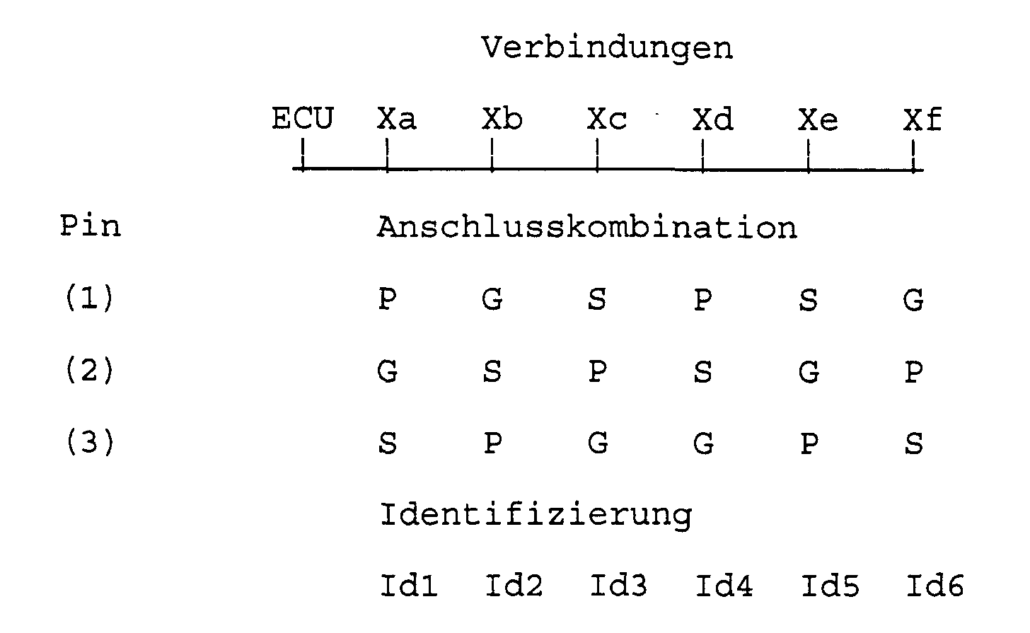
- the invention is briefly illustrated by the following example explained. It becomes a bus system between a control unit (ECU and six sensors (Xa to Xf) are used
- the bus system is equipped with three connection lines, namely a supply line P, a ground line G and a signal line S for communication.
- Each sensor (X) has three connection pins (1), (2), (3).
- the sensors are constructed identically. You have one Assignment table to your from the connection combination To choose identification. In the example, the sensor recognizes Xa its connection combination "P at pin 1, G at pin 2, S at pin 3 "and uses it to identify itself as "Id1".
- the control unit can use this identification (ECU) address the sensor.
- the Selection logic the connection selection of signal input and signal output drivers. Via the assignment table the identification is determined.
- bus participant through lines P, G and S to 6 bus participants can be identified.
- the Communication can be with an external control device or only between bus participants (master-slave or multi-master Principle).
- the identification can take place instead of or In addition to addressing, the functionality of the Bus participant be deposited. (Example: Idl initiated the sensor for measuring red light, Id2 for measuring green light.)
- identification can only be made via the two supply lines take place.
- An addressing is of course not possible without signal line, however can do two different functions can be selected.
Landscapes
- Engineering & Computer Science (AREA)
- Computer Networks & Wireless Communication (AREA)
- Signal Processing (AREA)
- Small-Scale Networks (AREA)
- Platform Screen Doors And Railroad Systems (AREA)
- Control Of Driving Devices And Active Controlling Of Vehicle (AREA)
- Mechanical Operated Clutches (AREA)
- Bus Control (AREA)
Abstract
Description
Claims (10)
- Bussystem mit mehreren Bussteilnehmern, wobei jeder Busteilnehmer an wenigstens zwei Anschlussleitungen angeschlossen ist, dadurch gekennzeichnet, dass jedem Busteilnehmer ein elektronisches Schaltungsteil zugewiesen ist, dass das Schaltungsteil in unterschiedlichen Anschlusskombinationen mit den Anschlussleitungen verbindbar ist, dass das Schaltungsteil die jeweilige Anschlusskombination der angeschlossenen Anschlussleitungen erkennt und dass das Schaltungsteil abhängig von der erkannten Anschlusskombination den Busteilnehmer codiert.
- Bussystem nach Anspruch 1, dadurch gekennzeichnet, dass das Schaltungsteil die Codierungen aller Anschlusskombinationen aufweist.
- Bussystem nach Anspruch 1 oder 2, dadurch gekennzeichnet, dass die Busteilnehmer gleich ausgebildet sind.
- Bussystem nach einem der vorhergehenden Ansprüche, dadurch gekennzeichnet, dass die Anschlussleitungen für Masse und Spannungsversorgung vorgesehen sind.
- Bussystem nach einem der vorhergehenden Ansprüche, dadurch gekennzeichnet, dass eine Anschlussleitung für Masse und eine Anschlussleitung als Signalleitung und für die Spannungsversorgung vorgesehen sind.
- Bussystem nach einem der Ansprüche 1 bis 3, dadurch gekennzeichnet, dass drei Anschlussleitungen für Masse, Spannungsversorgung und Steuersignale vorgesehen sind.
- Bussystem nach einem der Ansprüche 1 bis 3, dadurch gekennzeichnet, dass vier Anschlussleitungen für Masse, Spannungsversorgung, Steuersignale A und Steuersignale B vorgesehen sind.
- Bussystem nach einem der vorhergehenden Ansprüche, dadurch gekennzeichnet, dass das Verhalten identischer Busteilnehmer durch die Anschlusskombination der Anschlussleitungen bestimmt wird.
- Bussystem nach einem der vorhergehenden Ansprüche, dadurch gekennzeichnet, dass das Schaltungsteil die Potentiale der Anschlussleitungen dem Busteilnehmer zuführt.
- Bussystem nach einem der vorhergehenden Ansprüche, dadurch gekennzeichnet, dass das Schaltungsteil in den Busteilnehmer integriert ist.
Applications Claiming Priority (2)
| Application Number | Priority Date | Filing Date | Title |
|---|---|---|---|
| DE10015438 | 2000-03-29 | ||
| DE10015438A DE10015438A1 (de) | 2000-03-29 | 2000-03-29 | Bussystem |
Publications (3)
| Publication Number | Publication Date |
|---|---|
| EP1139609A2 true EP1139609A2 (de) | 2001-10-04 |
| EP1139609A3 EP1139609A3 (de) | 2004-04-14 |
| EP1139609B1 EP1139609B1 (de) | 2006-04-12 |
Family
ID=7636733
Family Applications (1)
| Application Number | Title | Priority Date | Filing Date |
|---|---|---|---|
| EP00125391A Expired - Lifetime EP1139609B1 (de) | 2000-03-29 | 2000-12-04 | Bussystem |
Country Status (4)
| Country | Link |
|---|---|
| EP (1) | EP1139609B1 (de) |
| AT (1) | ATE323306T1 (de) |
| DE (2) | DE10015438A1 (de) |
| ES (1) | ES2258953T3 (de) |
Cited By (4)
| Publication number | Priority date | Publication date | Assignee | Title |
|---|---|---|---|---|
| WO2010127917A1 (de) * | 2009-05-06 | 2010-11-11 | Robert Bosch Gmbh | Sensor-system und verfahren zum betreiben eines sensor-systems |
| DE102010033545A1 (de) | 2010-08-05 | 2012-02-09 | Valeo Schalter Und Sensoren Gmbh | Kontaktierungsvorrichtung mit Schneidklemmen zur Adresskodierung |
| WO2013170929A1 (de) * | 2012-05-15 | 2013-11-21 | Audi Ag | Busteilnehmer für ein bussystem, bussystem für einen kraftwagen sowie ein verfahren zur zuordnung von adressen in einem bussystem |
| WO2017064280A1 (en) * | 2015-10-14 | 2017-04-20 | Vodafone Automotive S.P.A. | Automatic setting of identifiers for a plurality of identical electronic components in an array |
Families Citing this family (4)
| Publication number | Priority date | Publication date | Assignee | Title |
|---|---|---|---|---|
| US6700480B2 (en) * | 2002-04-29 | 2004-03-02 | Robert Bosch Corporation | Addressable vehicle monitoring system and method |
| DE10358106A1 (de) * | 2003-12-12 | 2005-07-14 | Daimlerchrysler Ag | Sensorelement und Bussystem in einem Kraftfahrzeug |
| DE102011012816B3 (de) * | 2010-12-30 | 2012-04-12 | Volkswagen Ag | Steuervorrichtung für ein Fahrzeug |
| DE102011012090A1 (de) * | 2011-02-23 | 2012-08-23 | Austriamicrosystems Ag | Elektronisches Bauteil mit Zuweisung einer Adresse an das Bauteil |
Family Cites Families (6)
| Publication number | Priority date | Publication date | Assignee | Title |
|---|---|---|---|---|
| DE2555806B1 (de) * | 1975-12-11 | 1977-05-05 | Siemens Ag | Schaltungsanordnung zur Auswahl eines Bausteins aus einer Vielzahl von Bausteinen |
| DE3116471A1 (de) * | 1981-04-25 | 1982-11-11 | Telefonbau Und Normalzeit Gmbh, 6000 Frankfurt | Adressierbare einrichtung |
| WO1988008138A1 (en) * | 1987-04-13 | 1988-10-20 | The Foxboro Company | Identity insert for electronic modules |
| DE4221410A1 (de) * | 1992-06-30 | 1994-01-05 | Leuze Electronic Gmbh & Co | Adressierung MultiNet |
| DE4315494C1 (de) * | 1993-05-10 | 1994-09-29 | Daimler Benz Ag | Anordnung und Verfahren zur Programmierung wenigstens eines Kfz-Steuergeräts |
| DE19851739C2 (de) * | 1998-11-10 | 2003-07-31 | Fahrzeugklimaregelung Gmbh | Vorrichtung zur Adressierung eines Busteilnehmers |
-
2000
- 2000-03-29 DE DE10015438A patent/DE10015438A1/de not_active Withdrawn
- 2000-12-04 EP EP00125391A patent/EP1139609B1/de not_active Expired - Lifetime
- 2000-12-04 ES ES00125391T patent/ES2258953T3/es not_active Expired - Lifetime
- 2000-12-04 AT AT00125391T patent/ATE323306T1/de not_active IP Right Cessation
- 2000-12-04 DE DE50012569T patent/DE50012569D1/de not_active Expired - Lifetime
Cited By (7)
| Publication number | Priority date | Publication date | Assignee | Title |
|---|---|---|---|---|
| WO2010127917A1 (de) * | 2009-05-06 | 2010-11-11 | Robert Bosch Gmbh | Sensor-system und verfahren zum betreiben eines sensor-systems |
| DE102010033545A1 (de) | 2010-08-05 | 2012-02-09 | Valeo Schalter Und Sensoren Gmbh | Kontaktierungsvorrichtung mit Schneidklemmen zur Adresskodierung |
| WO2013170929A1 (de) * | 2012-05-15 | 2013-11-21 | Audi Ag | Busteilnehmer für ein bussystem, bussystem für einen kraftwagen sowie ein verfahren zur zuordnung von adressen in einem bussystem |
| CN104303461A (zh) * | 2012-05-15 | 2015-01-21 | 奥迪股份公司 | 用于总线系统的总线用户,用于汽车的总线系统以及用于在总线系统中分配地址的方法 |
| US9244859B2 (en) | 2012-05-15 | 2016-01-26 | Audi Ag | Bus subscriber for a bus system, bus system for a motor vehicle, and method for allocating addresses in a bus system |
| CN104303461B (zh) * | 2012-05-15 | 2017-09-26 | 奥迪股份公司 | 用于总线系统的总线用户,用于汽车的总线系统以及用于在总线系统中分配地址的方法 |
| WO2017064280A1 (en) * | 2015-10-14 | 2017-04-20 | Vodafone Automotive S.P.A. | Automatic setting of identifiers for a plurality of identical electronic components in an array |
Also Published As
| Publication number | Publication date |
|---|---|
| EP1139609A3 (de) | 2004-04-14 |
| DE10015438A1 (de) | 2001-10-04 |
| ATE323306T1 (de) | 2006-04-15 |
| ES2258953T3 (es) | 2006-09-16 |
| DE50012569D1 (de) | 2006-05-24 |
| EP1139609B1 (de) | 2006-04-12 |
Similar Documents
| Publication | Publication Date | Title |
|---|---|---|
| DE112013003260B4 (de) | Verfahren und Vorrichtung zum Betreiben von Zubehörschnittstellenfunktionen über ein Einzelsignal | |
| DE10055163B4 (de) | Datenbus, insbesondere in Kraftfahrzeugen | |
| DE69825004T2 (de) | Automatische Konfiguration von Primär- und Sekundärperipheriegeräte für einen Rechner | |
| DE69523223T2 (de) | Steuergerät | |
| DE10317331B4 (de) | System und Verfahren für die adressierbare Fahrzeugüberwachung | |
| EP1490772A1 (de) | Verfahren zum adressieren der teilnehmer eines bussystems mittels identifizierungsströmen | |
| EP1374488B1 (de) | Busmaster für einen bus zum anschluss von sensoren und/oder zündmitteln | |
| DE102016109741B4 (de) | Testpunktkarten-Einrichtung für einen Prüftisch | |
| DE102007028928A1 (de) | Slavegerät für Reihenschaltung und Verfahren zum Ermitteln der Position von Slavengeräten in einer Reihenschaltung | |
| EP1455278A1 (de) | Verfahren zur Identifizierung einer elektronischen Einheit | |
| WO2019034511A1 (de) | Verfahren zum betreiben einer sensoranordnung in einem kraftfahrzeug auf basis eines dsi-protokolls | |
| EP1139609B1 (de) | Bussystem | |
| DE102008005317A1 (de) | Verfahren zur Konfiguration eines ultraschallbasierten Fahrerassistenzsystems und korrespondierender Ultraschallsensor | |
| DE102013018282A1 (de) | Verfahren zur Identifizierung der relativen Einbauposition der in einem modularen elektronischen System zur Verwendung kommenden Module | |
| DE102004034248A1 (de) | Elektronische Schaltung mit galvanisch getrennten Baugruppen | |
| DE202018006079U1 (de) | Busknoten der zur Ausführung eines Verfahrens zur Vergabe von logischen Busknotenadressen geeignet ist, das für beliebige Datenbus-Topologien geeignet ist | |
| EP3047635B1 (de) | Feldbuskoppler zur anbindung von modulen an einen feldbus und verfahren zur adressierung derartiger module | |
| WO2003034368A2 (de) | Verfahren zur übertragung von daten von wenigstens einem sensor zu einem steuergerät | |
| DE3921962A1 (de) | Identifikationsvorrichtung fuer messgeber | |
| EP2181323B1 (de) | Feldgerät für die prozessautomatisierung | |
| DE102019103223A1 (de) | Vorrichtung und Verfahren zur Signalisierung eines Datenbusausfalls durch eine Ultraschallmessvorrichtung | |
| DE10308183B4 (de) | Elektronische Einrichtung zur Ansteuerung von in einer Ventileinheit gruppiert angeordneten Ventilen | |
| DE102019212414A1 (de) | Verfahren zur Positionserkennung eines Busteilnehmers | |
| DE102005057309A1 (de) | Steuergerät zur Datenübertragung in Datenbussen und Verfahren zu dessen Betrieb | |
| DE102008061435A1 (de) | Mit einer Vakuumpumpe verbindbares Gerät |
Legal Events
| Date | Code | Title | Description |
|---|---|---|---|
| PUAI | Public reference made under article 153(3) epc to a published international application that has entered the european phase |
Free format text: ORIGINAL CODE: 0009012 |
|
| AK | Designated contracting states |
Kind code of ref document: A2 Designated state(s): AT BE CH CY DE DK ES FI FR GB GR IE IT LI LU MC NL PT SE TR |
|
| AX | Request for extension of the european patent |
Free format text: AL;LT;LV;MK;RO;SI |
|
| PUAL | Search report despatched |
Free format text: ORIGINAL CODE: 0009013 |
|
| AK | Designated contracting states |
Kind code of ref document: A3 Designated state(s): AT BE CH CY DE DK ES FI FR GB GR IE IT LI LU MC NL PT SE TR |
|
| AX | Request for extension of the european patent |
Extension state: AL LT LV MK RO SI |
|
| RIC1 | Information provided on ipc code assigned before grant |
Ipc: 7H 04L 12/40 B Ipc: 7G 06F 12/06 A |
|
| 17P | Request for examination filed |
Effective date: 20041014 |
|
| 17Q | First examination report despatched |
Effective date: 20041118 |
|
| AKX | Designation fees paid |
Designated state(s): AT BE CH CY DE DK ES FI FR GB GR IE IT LI LU MC NL PT SE TR |
|
| GRAP | Despatch of communication of intention to grant a patent |
Free format text: ORIGINAL CODE: EPIDOSNIGR1 |
|
| RTI1 | Title (correction) |
Free format text: BUS SYSTEM |
|
| GRAS | Grant fee paid |
Free format text: ORIGINAL CODE: EPIDOSNIGR3 |
|
| GRAA | (expected) grant |
Free format text: ORIGINAL CODE: 0009210 |
|
| AK | Designated contracting states |
Kind code of ref document: B1 Designated state(s): AT BE CH CY DE DK ES FI FR GB GR IE IT LI LU MC NL PT SE TR |
|
| PG25 | Lapsed in a contracting state [announced via postgrant information from national office to epo] |
Ref country code: IE Free format text: LAPSE BECAUSE OF FAILURE TO SUBMIT A TRANSLATION OF THE DESCRIPTION OR TO PAY THE FEE WITHIN THE PRESCRIBED TIME-LIMIT Effective date: 20060412 Ref country code: NL Free format text: LAPSE BECAUSE OF FAILURE TO SUBMIT A TRANSLATION OF THE DESCRIPTION OR TO PAY THE FEE WITHIN THE PRESCRIBED TIME-LIMIT Effective date: 20060412 Ref country code: FI Free format text: LAPSE BECAUSE OF FAILURE TO SUBMIT A TRANSLATION OF THE DESCRIPTION OR TO PAY THE FEE WITHIN THE PRESCRIBED TIME-LIMIT Effective date: 20060412 |
|
| REG | Reference to a national code |
Ref country code: GB Ref legal event code: FG4D Free format text: NOT ENGLISH |
|
| REG | Reference to a national code |
Ref country code: CH Ref legal event code: EP |
|
| GBT | Gb: translation of ep patent filed (gb section 77(6)(a)/1977) |
Effective date: 20060412 |
|
| REF | Corresponds to: |
Ref document number: 50012569 Country of ref document: DE Date of ref document: 20060524 Kind code of ref document: P |
|
| REG | Reference to a national code |
Ref country code: IE Ref legal event code: FG4D Free format text: LANGUAGE OF EP DOCUMENT: GERMAN |
|
| PG25 | Lapsed in a contracting state [announced via postgrant information from national office to epo] |
Ref country code: DK Free format text: LAPSE BECAUSE OF FAILURE TO SUBMIT A TRANSLATION OF THE DESCRIPTION OR TO PAY THE FEE WITHIN THE PRESCRIBED TIME-LIMIT Effective date: 20060712 Ref country code: SE Free format text: LAPSE BECAUSE OF FAILURE TO SUBMIT A TRANSLATION OF THE DESCRIPTION OR TO PAY THE FEE WITHIN THE PRESCRIBED TIME-LIMIT Effective date: 20060712 |
|
| PG25 | Lapsed in a contracting state [announced via postgrant information from national office to epo] |
Ref country code: PT Free format text: LAPSE BECAUSE OF FAILURE TO SUBMIT A TRANSLATION OF THE DESCRIPTION OR TO PAY THE FEE WITHIN THE PRESCRIBED TIME-LIMIT Effective date: 20060912 |
|
| REG | Reference to a national code |
Ref country code: ES Ref legal event code: FG2A Ref document number: 2258953 Country of ref document: ES Kind code of ref document: T3 |
|
| NLV1 | Nl: lapsed or annulled due to failure to fulfill the requirements of art. 29p and 29m of the patents act | ||
| REG | Reference to a national code |
Ref country code: IE Ref legal event code: FD4D |
|
| ET | Fr: translation filed | ||
| PG25 | Lapsed in a contracting state [announced via postgrant information from national office to epo] |
Ref country code: LI Free format text: LAPSE BECAUSE OF NON-PAYMENT OF DUE FEES Effective date: 20061231 Ref country code: BE Free format text: LAPSE BECAUSE OF NON-PAYMENT OF DUE FEES Effective date: 20061231 Ref country code: MC Free format text: LAPSE BECAUSE OF NON-PAYMENT OF DUE FEES Effective date: 20061231 Ref country code: CH Free format text: LAPSE BECAUSE OF NON-PAYMENT OF DUE FEES Effective date: 20061231 |
|
| PLBE | No opposition filed within time limit |
Free format text: ORIGINAL CODE: 0009261 |
|
| STAA | Information on the status of an ep patent application or granted ep patent |
Free format text: STATUS: NO OPPOSITION FILED WITHIN TIME LIMIT |
|
| 26N | No opposition filed |
Effective date: 20070115 |
|
| REG | Reference to a national code |
Ref country code: CH Ref legal event code: PL |
|
| BERE | Be: lapsed |
Owner name: VALEO SCHALTER UND SENSOREN G.M.B.H. Effective date: 20061231 |
|
| PG25 | Lapsed in a contracting state [announced via postgrant information from national office to epo] |
Ref country code: AT Free format text: LAPSE BECAUSE OF NON-PAYMENT OF DUE FEES Effective date: 20061204 |
|
| PG25 | Lapsed in a contracting state [announced via postgrant information from national office to epo] |
Ref country code: GR Free format text: LAPSE BECAUSE OF FAILURE TO SUBMIT A TRANSLATION OF THE DESCRIPTION OR TO PAY THE FEE WITHIN THE PRESCRIBED TIME-LIMIT Effective date: 20060713 |
|
| PG25 | Lapsed in a contracting state [announced via postgrant information from national office to epo] |
Ref country code: TR Free format text: LAPSE BECAUSE OF FAILURE TO SUBMIT A TRANSLATION OF THE DESCRIPTION OR TO PAY THE FEE WITHIN THE PRESCRIBED TIME-LIMIT Effective date: 20060412 Ref country code: LU Free format text: LAPSE BECAUSE OF NON-PAYMENT OF DUE FEES Effective date: 20061204 |
|
| PG25 | Lapsed in a contracting state [announced via postgrant information from national office to epo] |
Ref country code: CY Free format text: LAPSE BECAUSE OF FAILURE TO SUBMIT A TRANSLATION OF THE DESCRIPTION OR TO PAY THE FEE WITHIN THE PRESCRIBED TIME-LIMIT Effective date: 20060412 |
|
| PGFP | Annual fee paid to national office [announced via postgrant information from national office to epo] |
Ref country code: ES Payment date: 20131219 Year of fee payment: 14 |
|
| REG | Reference to a national code |
Ref country code: FR Ref legal event code: PLFP Year of fee payment: 16 |
|
| REG | Reference to a national code |
Ref country code: ES Ref legal event code: FD2A Effective date: 20160126 |
|
| PG25 | Lapsed in a contracting state [announced via postgrant information from national office to epo] |
Ref country code: ES Free format text: LAPSE BECAUSE OF NON-PAYMENT OF DUE FEES Effective date: 20141205 |
|
| REG | Reference to a national code |
Ref country code: FR Ref legal event code: PLFP Year of fee payment: 17 |
|
| REG | Reference to a national code |
Ref country code: FR Ref legal event code: PLFP Year of fee payment: 18 |
|
| PGFP | Annual fee paid to national office [announced via postgrant information from national office to epo] |
Ref country code: DE Payment date: 20191216 Year of fee payment: 20 |
|
| PGFP | Annual fee paid to national office [announced via postgrant information from national office to epo] |
Ref country code: FR Payment date: 20191231 Year of fee payment: 20 Ref country code: IT Payment date: 20191216 Year of fee payment: 20 |
|
| PGFP | Annual fee paid to national office [announced via postgrant information from national office to epo] |
Ref country code: GB Payment date: 20191220 Year of fee payment: 20 |
|
| REG | Reference to a national code |
Ref country code: DE Ref legal event code: R071 Ref document number: 50012569 Country of ref document: DE |
|
| REG | Reference to a national code |
Ref country code: GB Ref legal event code: PE20 Expiry date: 20201203 |
|
| PG25 | Lapsed in a contracting state [announced via postgrant information from national office to epo] |
Ref country code: GB Free format text: LAPSE BECAUSE OF EXPIRATION OF PROTECTION Effective date: 20201203 |