EP1138984A2 - Wählhebelschaltung für ein Getriebe in einem Fahrzeug - Google Patents
Wählhebelschaltung für ein Getriebe in einem Fahrzeug Download PDFInfo
- Publication number
- EP1138984A2 EP1138984A2 EP01104955A EP01104955A EP1138984A2 EP 1138984 A2 EP1138984 A2 EP 1138984A2 EP 01104955 A EP01104955 A EP 01104955A EP 01104955 A EP01104955 A EP 01104955A EP 1138984 A2 EP1138984 A2 EP 1138984A2
- Authority
- EP
- European Patent Office
- Prior art keywords
- selector lever
- signal
- alley
- sensors
- signal transmitter
- Prior art date
- Legal status (The legal status is an assumption and is not a legal conclusion. Google has not performed a legal analysis and makes no representation as to the accuracy of the status listed.)
- Granted
Links
- 230000005540 biological transmission Effects 0.000 claims description 31
- 230000004913 activation Effects 0.000 claims description 9
- 238000003745 diagnosis Methods 0.000 claims description 7
- 235000014676 Phragmites communis Nutrition 0.000 claims description 3
- 238000012545 processing Methods 0.000 claims description 3
- 230000008859 change Effects 0.000 abstract description 3
- 230000003213 activating effect Effects 0.000 description 2
- 230000008878 coupling Effects 0.000 description 2
- 238000010168 coupling process Methods 0.000 description 2
- 238000005859 coupling reaction Methods 0.000 description 2
- 238000012544 monitoring process Methods 0.000 description 2
- 230000001133 acceleration Effects 0.000 description 1
- 238000004026 adhesive bonding Methods 0.000 description 1
- 238000012937 correction Methods 0.000 description 1
- 230000002950 deficient Effects 0.000 description 1
- 230000001419 dependent effect Effects 0.000 description 1
- 238000001514 detection method Methods 0.000 description 1
- 238000006073 displacement reaction Methods 0.000 description 1
- 238000011156 evaluation Methods 0.000 description 1
- 230000009347 mechanical transmission Effects 0.000 description 1
- 238000000034 method Methods 0.000 description 1
- 230000007935 neutral effect Effects 0.000 description 1
- 230000008569 process Effects 0.000 description 1
- 230000009467 reduction Effects 0.000 description 1
- 230000008054 signal transmission Effects 0.000 description 1
- 230000000007 visual effect Effects 0.000 description 1
Images

Classifications
-
- F—MECHANICAL ENGINEERING; LIGHTING; HEATING; WEAPONS; BLASTING
- F16—ENGINEERING ELEMENTS AND UNITS; GENERAL MEASURES FOR PRODUCING AND MAINTAINING EFFECTIVE FUNCTIONING OF MACHINES OR INSTALLATIONS; THERMAL INSULATION IN GENERAL
- F16H—GEARING
- F16H59/00—Control inputs to control units of change-speed- or reversing-gearings for conveying rotary motion
- F16H59/02—Selector apparatus
- F16H59/0204—Selector apparatus for automatic transmissions with means for range selection and manual shifting, e.g. range selector with tiptronic
-
- F—MECHANICAL ENGINEERING; LIGHTING; HEATING; WEAPONS; BLASTING
- F16—ENGINEERING ELEMENTS AND UNITS; GENERAL MEASURES FOR PRODUCING AND MAINTAINING EFFECTIVE FUNCTIONING OF MACHINES OR INSTALLATIONS; THERMAL INSULATION IN GENERAL
- F16H—GEARING
- F16H59/00—Control inputs to control units of change-speed- or reversing-gearings for conveying rotary motion
- F16H59/02—Selector apparatus
- F16H59/08—Range selector apparatus
- F16H59/10—Range selector apparatus comprising levers
- F16H59/105—Range selector apparatus comprising levers consisting of electrical switches or sensors
-
- F—MECHANICAL ENGINEERING; LIGHTING; HEATING; WEAPONS; BLASTING
- F16—ENGINEERING ELEMENTS AND UNITS; GENERAL MEASURES FOR PRODUCING AND MAINTAINING EFFECTIVE FUNCTIONING OF MACHINES OR INSTALLATIONS; THERMAL INSULATION IN GENERAL
- F16H—GEARING
- F16H59/00—Control inputs to control units of change-speed- or reversing-gearings for conveying rotary motion
- F16H59/02—Selector apparatus
- F16H2059/0239—Up- and down-shift or range or mode selection by repeated movement
Definitions
- DE 44 27 330 A1 describes an arrangement for detecting a set one Switch position on a motor vehicle manual transmission, in particular with an H shift known. With the help of several switches and two switch lever contacts, the Deflection of the shift lever as well as the movement in the shift gate determined, the shift lever being monitored in the neutral shift position.
- DE 197 48 115 A1 discloses a device for electromechanical switching a gear change transmission. There are at least two to detect the switching position Magnets are provided spaced apart on the circumference of the switching element. Hall sensors that are aligned with these magnets take the displacement of the Switching element was. For each position there is a specific pattern from the Hall sensors Measured field strength definable, so that the position of the switching element is independent of absolute measured values.
- An arrangement for detecting the position of a selector or shift lever within an automatic lane is known from DE 196 53 193 A1.
- the selector lever is with a multi-membered contact spring electrically connected, on which a contact plate is moved back and forth with the adjustment lever.
- the order ensures that the circuit arrangement for detecting the lever position also during temporary signal errors, for example temporary contact errors, intact remains.
- the ascertained are in an error detection and correction circuit Signals read in and according to a predetermined assignment rule, which in a Table is stored, converted into a corrected signal.
- Corresponds to a read Bit pattern a driving range, this signal is pushed through. However, becomes a defective bit pattern is recognized, based on the table a recognized driving range corresponding (corrected) signal output.
- EP 0 798 146 B1 describes a guide device for a selector lever for a Automatic transmission revealed.
- a selector lever position Drive
- the selector lever from the shift gate into a manual shift gate Telegasse
- Another guide device is known from the generic DE 196 50 154 A1.
- an automatic switching device with a tip alley described.
- a Shift or selector lever a magnet as the first activation element on one Printed circuit board installed sensors along. This triggers a signal in the sensors from what is processed by a transmission processor and sent to the control signal Transmission control is forwarded.
- a second activation element mostly also A magnet is attached to individual sensors when the gear lever is moved in Tipgasse out along Tipgasse, with a corresponding one in the respective sensors Signal is caused, which is further processed and both to the Transmission control as well as the gear position indicator is forwarded.
- EP 0 783 081 A1 discloses the backlighting of a translucent diaphragm visible position indicator of a selector lever position.
- the presence of the activation elements is considered also provided the sensors. Especially with automatic transmissions with Automatic shift lane and tip lane contain this prerequisite for accident risks.
- the object of the invention is to show a selector lever circuit at which, with a minimum of components, the presence of those necessary for the circuitry Gearbox and / or selector lever position indicator necessary electronic Components is checked.
- the invention is based on the idea of coupling two signal transmitters with a selector lever in such a way that when the selector lever is moved, a signal transmitter in the first alley (automatic shift gate) is guided past signal pickups in the first alley, while the second signal transmitter in the second alley (step shift gate, Tipgasse) one after the other out of the influence areas of the signal pickups of the second alley or back into it later.
- a signal transmitter in the first alley automated shift gate
- step shift gate, Tipgasse step shift gate, Tipgasse
- a diagnosis of the presence of certain electronic components of a selector lever circuit that are at least necessary for shifting the transmission or controlling the transmission control can be carried out beforehand and while driving, a signal being output by diagnostic electronics in the absence of a corresponding signal, which can lead to the decommissioning of a motor vehicle or commercial vehicle.
- signal sensors i.e. sensors of the first as well as the second alley
- diagnostic electronics With the help of these signals the presence or Absence of the first signal transmitter as well as the signal pick-up in the second alley checked.
- the first signal transmitter is direct with a selector lever, for example by snapping it into place and / or gluing into a corresponding receptacle etc. or indirectly through Transmission elements, such as slide or Bowden cable, connected, being a direct Attachment to the selector lever is advantageous.
- the diagnostic electronics can do this in any selector lever position
- Existence of the activation element in the first alley can be checked what particularly important when swiveling the selector lever into the second alley is when the first signal transmitter in the first lane is also used as a signal transmitter in the second Alley is used and for this purpose the first signal transmitter from the first alley using the Selector lever is guided into the second alley.
- the Sensors in the second lane are checked individually and one after the other.
- the second signal generator is switched off Influence range of the transducers in the second alley moved out to the Functional task of the signal pickups (manual speed adjustment) in the second lane not to be influenced when driving.
- the diagnostic electronics are preferably on a common printed circuit board Electronic circuit of the transmission control and / or the selector lever circuit integrated and for example underneath a selector lever cover, also called an aperture, appropriate.
- the signal pickups work with the signal transmitters without contact.
- the signal pickups can be magnetic field-dependent sensors, for example Hall sensor, reed contact or magnetic contact if the signal transmitters are magnets.
- the selector lever circuit 1 shows a selector lever circuit 1 with a first alley 2, an automatic shift gate, and a second alley 3, a tip alley, for an automatic transmission, not shown, of a motor or commercial vehicle.
- 4 is a selector lever, which is moved within the alleys 2, 3 and can be pivoted from one alley 2, 3 into the other.
- the selector lever circuit 1 has a selector lever cover (panel) 5, which frames the alleys 2, 3.
- Backlit selector lever position indicators 6 for selector lever positions P, R, N, D, S, M + and M- to be set in the alleys 2, 3 are preferably mounted in the selector lever cover 5. For the sake of clarity, these are identified by 20, which also includes the selector lever position M GE which is not backlit.
- sensors 7 to 14 are arranged, which for the sake of clarity are shown graphically directly on the selector lever position indicators 6.
- the sensors 7 to 14 and the lamps of the selector lever position indicators 6, which are not shown in detail, are preferably located together with other components of the selector lever circuit 1 on a circuit board, not shown, behind the selector lever cover 5.
- the sensors 7 to 14, which work without contact, are usually Hall sensors, magnetic or reed contacts, the signals P a , P aR , P aN , P aD , P aS and M GE , M + and M- for the electronics deliver a transmission control (not shown) and / or engage the respective selector lever position indicator 6.
- These signals P a , P aR , P aN , P aD , P aS of the automatic shift gate 2 and M GE , M + and M- of the tip gate 3 are caused by a first signal generator M1 as an activation element, for example a magnet, on the sensors 7 to 14 .
- a first signal generator M1 as an activation element, for example a magnet
- only one activation element M1 is part of the selector lever circuit 1.
- sensors 7 to 11 in particular, but primarily sensor 7 are used to diagnose the presence of first signal transmitter M1.
- the sensors 7 to 14 are electrically connected to a diagnosis electronics 15, which evaluates the signals of the sensors 7 to 14 and processes them, for example, for the electronics of the transmission control of the automatic transmission, which are not shown in detail.
- the first signal transmitter M1 serves primarily for the actual recognition of the set one Selector lever position or position 20 and / or a resulting one Function selection for the electronics of the transmission control and is done using the selector lever 4 connected in such a way that when the selector lever 4 is moved, the signal transmitter M1 is also adjusted will and.
- this signal generator M1 is preferably in a more direct manner Attached to sensor 7.
- Another signal transmitter M2 for example also a magnet, is with the selector lever 4 and the first Slgnalgeber M1 functionally connected.
- the second signal transmitter M2 is used for the diagnosis of sensors 12 to 14 in Tipgasse 3, preferably on Magnetic field responsive contacts.
- This second signal transmitter M2 is also with the Selector lever 4 connected such that when the selector lever 4 is adjusted Diagnostic element M2 is also adjusted.
- the diagnostic element M2 is relative to Activating magnet M1 arranged that in the selector lever position P of the selector lever 4 the second signal transmitter M2 with all three sensors 12 to 14, preferably simultaneously contacted.
- the second signal generator M2 can be segmented or simpler Be a magnet. This results in the necessary length of the signal transmitter M2. But it is also possible to assign isolated signal transmitters to sensors 12 to 14, so that each Only one sensor 12, 13 or 14 at a time when the selector lever 4 is moved being affected.
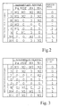
- FIGS. 2 and 3 The evaluation and processing of these signals is tabular in FIGS. 2 and 3 shown.
- processing signals error-detecting signals
- example Signals to be output to the electronics of the transmission control error reporting Signals
- the signals Pa, M GE , M +, M- are initiated by the sensors 7 to 14 and the signal transmitters M1 and / or M2.
- a pre-diagnosis is preferably carried out in the selector lever position P (parking), which can already be done, for example, by inserting the ignition key into the ignition lock (not shown in detail).
- the first signal generator M1 is present, the signal Pa is generated by the sensor 7 and the signals M GE , M + and M- are generated by the second signal generator M2 and the sensors 12 to 14.
- These individual signals arriving in the diagnostic electronics 15 are evaluated internally, here by comparison with a stored pattern. In a first statement, this information arrives at the electronics of the transmission control, whereby it receives information about the presence of the first signal transmitter M1 and the function of the individual sensors 12 to 14 in the tip alley 3.
- the electronics of the transmission control are informed that either the first signal transmitter M1 or at least one of the sensors 7, 12, 13 or 14 are not functionally, ie, hardware, present. Additional measures can then be used to prevent the vehicle from starting.
- This first meaningful diagnosis is preferably followed by further monitoring while driving.
- the signal generator M1 is adjusted in the direction R, specifically when the vehicle is to drive in reverse.
- a signal Pa R is generated, which is registered internally in the diagnostic electronics 15 and evaluated internally as "signal transmitter M1 still present”.
- the second signal transmitter M2 is also adjusted, which is now guided out of the area of influence of the sensor 13 and only responds to the sensors 12 and 14, as a result of which the signals M GE and M- are generated.
- the absence of the M + signal is recognized as correct in the diagnostic electronics 15.
- only the signal Pa R is given to the electronics of the transmission control if the electronics of the transmission control require such a signal from the sensor 8.
- a signal Pa N is generated by the first signal transmitter M1 at the sensor 9, while the second signal transmitter M2 at the sensor 14 only causes the signal M-.
- the absence of the signals M + and M GE in the diagnostic electronics 15 is defined as correct.
- the signal Pa N also arrives at the electronics of the transmission control independently of the diagnostic electronics 15.
- the first signal transmitter M1 is connected to the sensor 10 and switches it, while the second signal transmitter M2 no longer influences any sensors 12 to 14.
- the generated signal Pa D is also used for internal monitoring for the presence of the magnet M1 in the selector lever position D.
- This information when the selector lever 4 is adjusted with regard to the presence of the individual signals M GE , M + and M- can be used to carry out a separate, ie also an individual analysis of the three sensors 12, 13, 14 within the diagnostic electronics 15 even before switching to to be able to make the selector lever position D.
- the selector lever 4 can be transferred to the tip alley 3 if desired. Since the first signal transmitter M1 now preferably also activates the sensors 12 to 14 in the tip alley 3, it is necessary to additionally indicate this middle position "M GE " to the electronics of the transmission control in order to inform the latter that the magnet M1 is in the tip alley located.
- the signals M GE , M + and M- are preferably ORed in the diagnostic electronics 15 by a transistor, not shown, ie the transistor used is connected as an OR gate.
- the M GE signal (selector lever center position in tipgasse 3) is also transmitted to the electronics of the transmission control system when the selector lever 4 is switched to the selector lever positions M + and M- in tipgasse 3 (wiper principle). In the selector lever positions P to N, this ORing of the sensor signals is switched off.
- the selector lever 4 When the selector lever 4 is transferred from the selector lever position "D" from the automatic shift gate 2 to the tip gate 3, the first signal transmitter M1 is routed to the sensor 12, as a result of which the sensor delivers the M GE signal.
- the signals M + and M- are not generated in this position.
- the selector lever 4 can now be adjusted within the tip gate 3 either to the selector lever position M + (acceleration) or selector lever position M- (reduction). This adjustment causes the sensors 13 or 14 to be activated by the first signal transmitter M1, which are sent to the electronics of the transmission control and to the diagnostic electronics 15. A separate diagnosis can, but does not have to be made at this point.
- sensors 7 to 14 cannot do any more Lamps shown in the selector lever cover 5 for a direct visual Diagnostic display can be used.
Landscapes
- Engineering & Computer Science (AREA)
- General Engineering & Computer Science (AREA)
- Mechanical Engineering (AREA)
- Arrangement Or Mounting Of Control Devices For Change-Speed Gearing (AREA)
- Control Of Transmission Device (AREA)
Abstract
Description
Der zweite Signalgeber ist im Unterschied zum ersten Signalgeber kein Aktivierungselement der Wählhebelschaltung für eine Getriebesteuerung, sondern ein sogenanntes Diagnoseelement.
Mit dieser Wählhebelschaltung kann vorab als auch während der Fahrt eine Diagnose auf das Vorhandensein bestimmter, zumindest für die Schaltung des Getriebes bzw. Ansteuerung der Getriebesteuerung notwendiger elektronischer Bauelemente einer Wählhebelschaltung vorgenommen werden, wobei bei Fehlen eines entsprechendes Signals durch eine Diagnoseelektronik ein Signal ausgegeben wird, was zur Stillegung eines Kraft- oder Nutzfahrzeuges führen kann.
- Fig. 1
- in einer Draufsichtdarstellung eine Wählhebelschaltung für ein Automatikgetriebe,
- Fig. 2
- eine tabellarische Darstellung der in einer Diagnoseelektronik zu verarbeitenden Signale,
- Fig. 3
- in tabellarischer Darstellung die von der Diagnoseelektronik auszugebenden Signale.
Die Sensoren 7 bis 14, die berührungslos arbeiten, sind in der Regel Hall-Sensoren, Magnet- oder Reedkontakte, die Signale Pa, PaR, PaN, PaD, PaS sowie MGE, M+ und M- für die Elektronik einer Getriebesteuerung (nicht näher dargestellt) liefern und/oder die jeweilige Wählhebelpositionsanzeige 6 zuschalten. Diese Signale Pa, PaR, PaN, PaD, PaS der Automatikschaltgasse 2 sowie MGE, M+ und M- der Tipgasse 3 werden durch einen ersten Signalgeber M1 als Aktivierungselement, beispielsweise ein Magnet, an den Sensoren 7 bis 14 hervorgerufen. In der bevorzugten und hier beschriebenen Ausführung ist nur ein Aktivierungselement M1 Bestandteil der Wählhebelschaltung 1.
In einer weiteren, speziellen Funktion dienen insbesondere die Sensoren 7 bis 11, vorrangig jedoch der Sensor 7, zur Diagnose auf das Vorhandenseins des ersten Signalgebers M1. Dazu sind die Sensoren 7 bis 14 mit eine Diagnoseelektronik 15 elektrisch verbunden, die die Signale der Sensoren 7 bis 14 auswertet und beispielsweise für die nicht näher dargestellte Elektronik der Getriebesteuerung des Automatikgetriebes aufbereitet.
Nach Verlassen des Wählhebels 4 aus der Wählhebelposition P wird zusammen mit dem Wählhebel 4 der Signalgeber M1 in Richtung R verstellt, und zwar dann, wenn das Fahrzeug rückwärts fahren soll. In dieser Wählhebelposition R wird, bedingt durch den Sensor 8 und dem verstellten ersten Siganlgeber M1, ein Signal PaR erzeugt, was in der Diagnoseelektronik 15 intern registriert und als " Signalgeber M1 weiterhin vorhanden" intern ausgewertet wird. Gleichzeitig mit der Verstellung des Wählhebels 4 wird auch der zweite Signalgeber M2 mit verstellt, der nun aus dem Einflußbereich des Sensors 13 geführt wird und nur noch die Sensoren 12 und 14 anspricht, wodurch die Signale MGE und M- generiert werden. Das Fehlen des Signals M+ wird in der Diagnoseelektronik 15 als richtig erkannt. An die Elektronik der Getriebesteuerung wird unabhängig von der Diagnoseelektronik 15 jedoch nur das Signal PaR gegeben, wenn die Elektronik der Getriebesteuerung ein derartiges Signal vom Sensor 8 benötigt.
Claims (10)
- Wählhebelschaltung (1) für ein Getriebe in einem Fahrzeugmit einer ersten Gasse (2) zum Anwählen von unterschiedlichen Fahrbereichen (P, R, N, D, S) und einer parallel dazu zweiten Gasse (3) zur sequentiellen Anwahl weiterer Fahrbereiche (M+, M-),mit einem Wählhebel (4) zum Einstellen der Fahrbereiche (P, R, N, D, S) sowie der sequentiell anwählbaren Fahrbereiche (M+, M-),mit Signalaufnehmer (7 bis 14) in der ersten Gasse (2) sowie in der zweiten Gasse (3) undmit einem ersten Signalgeber (M1) in der ersten Gasse (2) und einem weiteren, zweiten Signalgeber (M2) in der zweiten Gasse (3), wobeibeide Signalgeber (M1, M2) derart mit dem Wählhebel (4) verbunden sind, daßbei Verstellung des Wählhebels (4) in der ersten Gasse (2) der erste Signalgeber (M1) jeweils mit den Signalaufnehmern (7 bis 11) der ersten Gasse (2) und der zweite Signalgeber (M2) mit den Signalaufnehmern (12 bis 14) der zweiten Gasse (3) zusammenwirkt, wobeider zweite Signalgeber (M2) relativ zum ersten Signalgeber (M1) derart angeordnet ist, daß dieser bei Stellung des Wählhebels (4) im Fahrbereich (P) die Signalaufnehmer (12 bis 14) der zweiten Gasse (3) anspricht und bei Verstellung des Wählhebels (4) in andere Fahrbereiche (R, N, D, S) innerhalb der ersten Gasse (2) nacheinander aus dem Einflußbereich der einzelnen Signalaufnehmer (12 bis 14) heraus geführt wird, wobeibei Verstellung des Wählhebels (4) in die zweite Gasse (3) der erste Signalgeber (M1) in den Einflußbereich der Signalaufnehmer (12 bis 14) der zweiten Gasse (3) geführt wird, unddie Signalaufnehmer (7 bis 14) mit einer Diagnoseelektronik (15) elektrisch verbunden sind.
- Wählhebelschaltung nach Anspruch 1, dadurch gekennzeichnet, daß der erste Signalgeber (M1) als Aktivierungselement der Wählhebelschaltung (1) und der zweite Signalgeber als Diagnoseelement (M2) fungiert.
- Wählhebelschaltung nach einem der Ansprüche 1 oder 2, dadurch gekennzeichnet, daß die beiden Signalgeber (M1, M2) berührungslos arbeitende Geber sind.
- Wählhebelschaltung nach einem der vorgenannten Ansprüche 1 bis 3, dadurch gekennzeichnet, daß die Signalaufnehmer (7 bis 14) berührungslos arbeitende Sensoren sind.
- Wählhebelschaltung nach einem oder mehreren der vorgenannten Ansprüche, dadurch gekennzeichnet, daß die Signalgeber (M1, M2) Magnete und die Signalaufnehmer (7 bis 14) Hall-Sensoren, Reed-Kontakte und/oder Magnetkontakte sind.
- Wählhebelschaltung nach einem der vorgenannten Ansprüche, dadurch gekennzeichnet, daß der zur Diagnose der Signalaufnehmer (12 bis14) in der zweiten Gasse (3) verwendete Signalgeber (M2) größenmäßig derart gestaltet ist, daß dieser in einer ersten Wählhebelposition (P) diese Sensoren (12 bis 14) gleichzeitig anspricht, wobei drei verschiedene Signale (MGE, M+, M-) erzeugt werden, die an der Diagnoseelektronik (15) zur internen Weiterverarbeitung gegeben werden.
- Wählhebelschaltung nach einem der vorgenannten Ansprüche, dadurch gekennzeichnet, daß die Prüfung auf das Vorhandensein des ersten Signalgebers (M1) in der ersten Gasse (2) und/oder der zumindest drei Signalaufnehmer (12 bis 14) in der zweiten Gasse (3) vorab im ersten Fahrbereich (P) erfolgt.
- Wählhebelschaltung nach einem der Ansprüche 1 bis 7, dadurch gekennzeichnet, daß zur Anzeige der eingestellten Position des Wählhebels (4) Wählpositionsanzeigen (6) in einer Wählhebelabdeckung (5) integriert sind.
- Wählhebelschaltung nach Anspruch 8, dadurch gekennzeichnet, daß die Wählpositionsanzeigen (6) hinterleuchtbar sind, wobei die Zuschaltung der Leuchten beim Verstellen des ersten Signalgebers (M1) bzw. des zweiten Signalgebers (M2) erfolgt, wozu die Sensoren (7-14) mit jeweils einer Leuchte hinter den Wählpositionsanzeigen (6) verbunden sind.
- Wählhebelschaltung nach einem der Ansprüche 1 bis 9, dadurch gekennzeichnet, die Diagnoseelektronik (15) mit weiteren Bauelementen der Wählhebelschaltung (1) und/oder der Elektronik der Getriebesteuerung gemeinsamen auf einer Leiterplatte angeordnet ist.
Applications Claiming Priority (4)
| Application Number | Priority Date | Filing Date | Title |
|---|---|---|---|
| DE10015432 | 2000-03-28 | ||
| DE10015432 | 2000-03-28 | ||
| DE10108267A DE10108267A1 (de) | 2000-03-28 | 2001-02-21 | Wählhebelschaltung für ein Getriebe in einem Fahrzeug |
| DE10108267 | 2001-02-21 |
Publications (3)
| Publication Number | Publication Date |
|---|---|
| EP1138984A2 true EP1138984A2 (de) | 2001-10-04 |
| EP1138984A3 EP1138984A3 (de) | 2003-10-01 |
| EP1138984B1 EP1138984B1 (de) | 2004-08-04 |
Family
ID=26005067
Family Applications (1)
| Application Number | Title | Priority Date | Filing Date |
|---|---|---|---|
| EP20010104955 Expired - Lifetime EP1138984B1 (de) | 2000-03-28 | 2001-03-01 | Wählhebelschaltung für ein Getriebe in einem Fahrzeug |
Country Status (2)
| Country | Link |
|---|---|
| EP (1) | EP1138984B1 (de) |
| ES (1) | ES2222281T3 (de) |
Cited By (4)
| Publication number | Priority date | Publication date | Assignee | Title |
|---|---|---|---|---|
| WO2005001314A1 (en) * | 2003-06-27 | 2005-01-06 | Kongsberg Automotive Ab | Device for symmetrical gear shift |
| WO2006101429A1 (en) * | 2005-03-22 | 2006-09-28 | Kongsberg Automotive Ab | A gear lever with extra detection |
| WO2018050228A1 (en) * | 2016-09-15 | 2018-03-22 | Kongsberg Automotive Ab | Arrangement for reading off predetermined positions of a gear lever in a gear selector in a vehicle |
| CN112261366A (zh) * | 2020-10-20 | 2021-01-22 | 贵州电网有限责任公司 | 一种运行监视装置 |
Citations (7)
| Publication number | Priority date | Publication date | Assignee | Title |
|---|---|---|---|---|
| DE4427330A1 (de) | 1994-08-02 | 1996-02-15 | Fichtel & Sachs Ag | Anordnung zum Erfassen einer an einem Kraftfahrzeugschaltgetriebe eingestellten Schaltstellung |
| EP0783081A1 (de) | 1995-04-26 | 1997-07-09 | Fico Triad S.A. | Anzeigeeinrichtung für die schalthebelposition einer automatischen getriebeschaltung |
| DE19650154A1 (de) | 1996-12-04 | 1998-06-10 | Lemfoerder Metallwaren Ag | Schaltvorrichtung für ein Getriebe eines KFZ mit einer gekrümmten Leiterplatte und Verfahren zur Herstellung dieser Leiterplatte |
| DE19653193A1 (de) | 1996-12-19 | 1998-07-02 | Siemens Ag | Anordnung zum Erfassen der Stellung eines Wählhebels oder Schalthebels in einem Kraftfahrzeug |
| DE19748115A1 (de) | 1997-10-31 | 1999-05-12 | Sican F & E Gmbh Sibet | Vorrichtung zum elektromechanischen Schalten eines Gangwechselgetriebes |
| DE19811972A1 (de) | 1998-03-19 | 1999-10-14 | Lemfoerder Metallwaren Ag | Wählvorrichtung für ein Automatikgetriebe eines Kraftfahrzeuges |
| EP0798146B1 (de) | 1996-03-29 | 2000-06-28 | Dr.Ing.h.c. F. Porsche Aktiengesellschaft | Gasse für einen Schalthebel |
Family Cites Families (2)
| Publication number | Priority date | Publication date | Assignee | Title |
|---|---|---|---|---|
| DE19821361B4 (de) * | 1997-05-22 | 2006-07-06 | Volkswagen Ag | Getriebeschalteinrichtung und Getriebesteuerungsverfahren |
| DE19938528A1 (de) * | 1999-08-13 | 2001-02-15 | Audi Ag | Steuereinrichtung für automatisch und manuell schaltbare Getriebe |
-
2001
- 2001-03-01 EP EP20010104955 patent/EP1138984B1/de not_active Expired - Lifetime
- 2001-03-01 ES ES01104955T patent/ES2222281T3/es not_active Expired - Lifetime
Patent Citations (7)
| Publication number | Priority date | Publication date | Assignee | Title |
|---|---|---|---|---|
| DE4427330A1 (de) | 1994-08-02 | 1996-02-15 | Fichtel & Sachs Ag | Anordnung zum Erfassen einer an einem Kraftfahrzeugschaltgetriebe eingestellten Schaltstellung |
| EP0783081A1 (de) | 1995-04-26 | 1997-07-09 | Fico Triad S.A. | Anzeigeeinrichtung für die schalthebelposition einer automatischen getriebeschaltung |
| EP0798146B1 (de) | 1996-03-29 | 2000-06-28 | Dr.Ing.h.c. F. Porsche Aktiengesellschaft | Gasse für einen Schalthebel |
| DE19650154A1 (de) | 1996-12-04 | 1998-06-10 | Lemfoerder Metallwaren Ag | Schaltvorrichtung für ein Getriebe eines KFZ mit einer gekrümmten Leiterplatte und Verfahren zur Herstellung dieser Leiterplatte |
| DE19653193A1 (de) | 1996-12-19 | 1998-07-02 | Siemens Ag | Anordnung zum Erfassen der Stellung eines Wählhebels oder Schalthebels in einem Kraftfahrzeug |
| DE19748115A1 (de) | 1997-10-31 | 1999-05-12 | Sican F & E Gmbh Sibet | Vorrichtung zum elektromechanischen Schalten eines Gangwechselgetriebes |
| DE19811972A1 (de) | 1998-03-19 | 1999-10-14 | Lemfoerder Metallwaren Ag | Wählvorrichtung für ein Automatikgetriebe eines Kraftfahrzeuges |
Cited By (7)
| Publication number | Priority date | Publication date | Assignee | Title |
|---|---|---|---|---|
| WO2005001314A1 (en) * | 2003-06-27 | 2005-01-06 | Kongsberg Automotive Ab | Device for symmetrical gear shift |
| US7614319B2 (en) | 2003-06-27 | 2009-11-10 | Kongsberg Automotive Ab | Device for symmetrical gear shift |
| WO2006101429A1 (en) * | 2005-03-22 | 2006-09-28 | Kongsberg Automotive Ab | A gear lever with extra detection |
| US8171816B2 (en) | 2005-03-22 | 2012-05-08 | Kongsberg Automotive Ab | Gear arrangement for vehicle including gear lever with multiple lever rods |
| WO2018050228A1 (en) * | 2016-09-15 | 2018-03-22 | Kongsberg Automotive Ab | Arrangement for reading off predetermined positions of a gear lever in a gear selector in a vehicle |
| US11371606B2 (en) | 2016-09-15 | 2022-06-28 | Kongsberg Automotive Ab | Arrangement for reading off predetermined positions of a gear lever in a gear selector in a vehicle |
| CN112261366A (zh) * | 2020-10-20 | 2021-01-22 | 贵州电网有限责任公司 | 一种运行监视装置 |
Also Published As
| Publication number | Publication date |
|---|---|
| EP1138984B1 (de) | 2004-08-04 |
| EP1138984A3 (de) | 2003-10-01 |
| ES2222281T3 (es) | 2005-02-01 |
Similar Documents
| Publication | Publication Date | Title |
|---|---|---|
| EP1240446B1 (de) | Steuereinrichtung für ein automatisch und manuell schaltbares schaltgetriebe in einem kraftfahrzeug | |
| DE19749330C2 (de) | Vorrichtung zum Erfassen von Schaltstellungen eines mechanisch betätigbaren Schaltmittels | |
| EP0075693B2 (de) | Gangwähler für ein Getriebe | |
| DE69130418T2 (de) | Diagnose für elektronisches übertragungssteuerungssystem | |
| EP0361011B1 (de) | Anzeigevorrichtung für ein automatisches Kraftfahzeuggetriebe | |
| DE10049307B4 (de) | Sensorik-System für die Steuereinrichtung eines automatisch schaltbaren Getriebes | |
| DE19608981A1 (de) | Schaltvorrichtung für ein Getriebe von Kraftfahrzeugen | |
| EP2791625B1 (de) | Sensorvorrichtung und verfahren zur positionserfassung sowie magnetelement für die sensorvorrichtung | |
| EP0794362A2 (de) | Schaltvorrichtung für ein Getriebe von Kraftfahrzeugen | |
| DE102007026303B4 (de) | Wählhebelmodul mit 3D-Magnetsensorelement | |
| WO2009052976A1 (de) | Sensor für die schaltstellung einer schaltwelle und entsprechendes ermittlungsverfahren | |
| DE19653193A1 (de) | Anordnung zum Erfassen der Stellung eines Wählhebels oder Schalthebels in einem Kraftfahrzeug | |
| EP1138984B1 (de) | Wählhebelschaltung für ein Getriebe in einem Fahrzeug | |
| DE4121410C1 (en) | Vehicle change-speed gear position recognising appts. - has hole mask which interrupts magnetic flux from permanent magnets to reed switches fitted directly to gears and activates position indicating circuit | |
| DE10108267A1 (de) | Wählhebelschaltung für ein Getriebe in einem Fahrzeug | |
| DE19748131A1 (de) | Vorrichtung zum Erfassen von Schaltstellungen eines mechanisch betätigbaren Schaltmittels sowie Verfahren zum Erfassen von Schaltstellungen eines mechanisch betätigbaren Schaltmittels | |
| DE19522656A1 (de) | Positionserkennungsvorrichtung für einen Wählhebel in Kraftfahrzeugen | |
| WO2022136130A1 (de) | Aktuator und vorrichtung zum einlegen einer parksperre eines kraftfahrzeugautomatikgetriebes mit einem derartigen aktuator sowie ein damit ausgestattetes kraftfahrzeug | |
| DE19707141A1 (de) | Anordnung zum Erfassen von Betätigungs- oder Schaltzuständen einer Getriebebetätigungsvorrichtung | |
| DE10227633A1 (de) | Codierter Getriebepositionsschalter | |
| DE102008058163A1 (de) | Vorrichtung zur Erfassung sämtlicher Schaltpositionen eines Schaltgetriebes | |
| DE10213763A1 (de) | Schaltvorrichtung zur Steuerung der Gangwahl eines Kraftfahrzeuggetriebes | |
| DE102004052797A1 (de) | Vorrichtung zur Positionserfassung von Schaltgabeln und/oder Gangstellern eines Getriebes | |
| DE19944203A1 (de) | Vorrichtung zum Erfassen einer Stellung eines Stellelements | |
| DE102007052978A1 (de) | Anordnung zur Erfassung eines Drehwinkels |
Legal Events
| Date | Code | Title | Description |
|---|---|---|---|
| PUAI | Public reference made under article 153(3) epc to a published international application that has entered the european phase |
Free format text: ORIGINAL CODE: 0009012 |
|
| AK | Designated contracting states |
Kind code of ref document: A2 Designated state(s): AT BE CH CY DE DK ES FI FR GB GR IE IT LI LU MC NL PT SE TR |
|
| AX | Request for extension of the european patent |
Free format text: AL;LT;LV;MK;RO;SI |
|
| PUAL | Search report despatched |
Free format text: ORIGINAL CODE: 0009013 |
|
| AK | Designated contracting states |
Kind code of ref document: A3 Designated state(s): AT BE CH CY DE DK ES FI FR GB GR IE IT LI LU MC NL PT SE TR |
|
| AX | Request for extension of the european patent |
Extension state: AL LT LV MK RO SI |
|
| 17P | Request for examination filed |
Effective date: 20031011 |
|
| GRAP | Despatch of communication of intention to grant a patent |
Free format text: ORIGINAL CODE: EPIDOSNIGR1 |
|
| GRAS | Grant fee paid |
Free format text: ORIGINAL CODE: EPIDOSNIGR3 |
|
| RAP1 | Party data changed (applicant data changed or rights of an application transferred) |
Owner name: PREH GMBH |
|
| GRAA | (expected) grant |
Free format text: ORIGINAL CODE: 0009210 |
|
| AKX | Designation fees paid |
Designated state(s): DE ES FR GB IT |
|
| AK | Designated contracting states |
Kind code of ref document: B1 Designated state(s): DE ES FR GB IT |
|
| REG | Reference to a national code |
Ref country code: GB Ref legal event code: FG4D Free format text: NOT ENGLISH |
|
| REG | Reference to a national code |
Ref country code: IE Ref legal event code: FG4D Free format text: GERMAN |
|
| REF | Corresponds to: |
Ref document number: 50103057 Country of ref document: DE Date of ref document: 20040909 Kind code of ref document: P |
|
| GBT | Gb: translation of ep patent filed (gb section 77(6)(a)/1977) |
Effective date: 20040825 |
|
| REG | Reference to a national code |
Ref country code: ES Ref legal event code: FG2A Ref document number: 2222281 Country of ref document: ES Kind code of ref document: T3 |
|
| PGFP | Annual fee paid to national office [announced via postgrant information from national office to epo] |
Ref country code: GB Payment date: 20050221 Year of fee payment: 5 |
|
| PGFP | Annual fee paid to national office [announced via postgrant information from national office to epo] |
Ref country code: FR Payment date: 20050311 Year of fee payment: 5 |
|
| PGFP | Annual fee paid to national office [announced via postgrant information from national office to epo] |
Ref country code: ES Payment date: 20050323 Year of fee payment: 5 |
|
| REG | Reference to a national code |
Ref country code: IE Ref legal event code: FD4D |
|
| ET | Fr: translation filed | ||
| PLBE | No opposition filed within time limit |
Free format text: ORIGINAL CODE: 0009261 |
|
| STAA | Information on the status of an ep patent application or granted ep patent |
Free format text: STATUS: NO OPPOSITION FILED WITHIN TIME LIMIT |
|
| 26N | No opposition filed |
Effective date: 20050506 |
|
| PG25 | Lapsed in a contracting state [announced via postgrant information from national office to epo] |
Ref country code: GB Free format text: LAPSE BECAUSE OF NON-PAYMENT OF DUE FEES Effective date: 20060301 |
|
| PG25 | Lapsed in a contracting state [announced via postgrant information from national office to epo] |
Ref country code: ES Free format text: LAPSE BECAUSE OF NON-PAYMENT OF DUE FEES Effective date: 20060302 |
|
| PGFP | Annual fee paid to national office [announced via postgrant information from national office to epo] |
Ref country code: IT Payment date: 20060331 Year of fee payment: 6 |
|
| GBPC | Gb: european patent ceased through non-payment of renewal fee |
Effective date: 20060301 |
|
| REG | Reference to a national code |
Ref country code: FR Ref legal event code: ST Effective date: 20061130 |
|
| REG | Reference to a national code |
Ref country code: ES Ref legal event code: FD2A Effective date: 20060302 |
|
| PG25 | Lapsed in a contracting state [announced via postgrant information from national office to epo] |
Ref country code: FR Free format text: LAPSE BECAUSE OF NON-PAYMENT OF DUE FEES Effective date: 20060331 |
|
| PGFP | Annual fee paid to national office [announced via postgrant information from national office to epo] |
Ref country code: DE Payment date: 20090320 Year of fee payment: 9 |
|
| PG25 | Lapsed in a contracting state [announced via postgrant information from national office to epo] |
Ref country code: IT Free format text: LAPSE BECAUSE OF NON-PAYMENT OF DUE FEES Effective date: 20070301 |
|
| PG25 | Lapsed in a contracting state [announced via postgrant information from national office to epo] |
Ref country code: DE Free format text: LAPSE BECAUSE OF NON-PAYMENT OF DUE FEES Effective date: 20101001 |