EP1138968B1 - Labyrinthdichtung für eine Gelenkkreuzwelle - Google Patents
Labyrinthdichtung für eine Gelenkkreuzwelle Download PDFInfo
- Publication number
- EP1138968B1 EP1138968B1 EP01107238A EP01107238A EP1138968B1 EP 1138968 B1 EP1138968 B1 EP 1138968B1 EP 01107238 A EP01107238 A EP 01107238A EP 01107238 A EP01107238 A EP 01107238A EP 1138968 B1 EP1138968 B1 EP 1138968B1
- Authority
- EP
- European Patent Office
- Prior art keywords
- seal
- seal body
- sealing
- recess
- bearing bushing
- Prior art date
- Legal status (The legal status is an assumption and is not a legal conclusion. Google has not performed a legal analysis and makes no representation as to the accuracy of the status listed.)
- Expired - Lifetime
Links
Images


Classifications
-
- F—MECHANICAL ENGINEERING; LIGHTING; HEATING; WEAPONS; BLASTING
- F16—ENGINEERING ELEMENTS AND UNITS; GENERAL MEASURES FOR PRODUCING AND MAINTAINING EFFECTIVE FUNCTIONING OF MACHINES OR INSTALLATIONS; THERMAL INSULATION IN GENERAL
- F16D—COUPLINGS FOR TRANSMITTING ROTATION; CLUTCHES; BRAKES
- F16D3/00—Yielding couplings, i.e. with means permitting movement between the connected parts during the drive
- F16D3/16—Universal joints in which flexibility is produced by means of pivots or sliding or rolling connecting parts
- F16D3/26—Hooke's joints or other joints with an equivalent intermediate member to which each coupling part is pivotally or slidably connected
- F16D3/38—Hooke's joints or other joints with an equivalent intermediate member to which each coupling part is pivotally or slidably connected with a single intermediate member with trunnions or bearings arranged on two axes perpendicular to one another
- F16D3/382—Hooke's joints or other joints with an equivalent intermediate member to which each coupling part is pivotally or slidably connected with a single intermediate member with trunnions or bearings arranged on two axes perpendicular to one another constructional details of other than the intermediate member
- F16D3/385—Bearing cup; Bearing construction; Bearing seal; Mounting of bearing on the intermediate member
-
- F—MECHANICAL ENGINEERING; LIGHTING; HEATING; WEAPONS; BLASTING
- F16—ENGINEERING ELEMENTS AND UNITS; GENERAL MEASURES FOR PRODUCING AND MAINTAINING EFFECTIVE FUNCTIONING OF MACHINES OR INSTALLATIONS; THERMAL INSULATION IN GENERAL
- F16C—SHAFTS; FLEXIBLE SHAFTS; ELEMENTS OR CRANKSHAFT MECHANISMS; ROTARY BODIES OTHER THAN GEARING ELEMENTS; BEARINGS
- F16C21/00—Combinations of sliding-contact bearings with ball or roller bearings, for exclusively rotary movement
- F16C21/005—Combinations of sliding-contact bearings with ball or roller bearings, for exclusively rotary movement the external zone of a bearing with rolling members, e.g. needles, being cup-shaped, with or without a separate thrust-bearing disc or ring, e.g. for universal joints
-
- F—MECHANICAL ENGINEERING; LIGHTING; HEATING; WEAPONS; BLASTING
- F16—ENGINEERING ELEMENTS AND UNITS; GENERAL MEASURES FOR PRODUCING AND MAINTAINING EFFECTIVE FUNCTIONING OF MACHINES OR INSTALLATIONS; THERMAL INSULATION IN GENERAL
- F16C—SHAFTS; FLEXIBLE SHAFTS; ELEMENTS OR CRANKSHAFT MECHANISMS; ROTARY BODIES OTHER THAN GEARING ELEMENTS; BEARINGS
- F16C33/00—Parts of bearings; Special methods for making bearings or parts thereof
- F16C33/72—Sealings
- F16C33/76—Sealings of ball or roller bearings
- F16C33/78—Sealings of ball or roller bearings with a diaphragm, disc, or ring, with or without resilient members
- F16C33/7803—Sealings of ball or roller bearings with a diaphragm, disc, or ring, with or without resilient members suited for particular types of rolling bearings
- F16C33/7809—Sealings of ball or roller bearings with a diaphragm, disc, or ring, with or without resilient members suited for particular types of rolling bearings for needle roller bearings
-
- F—MECHANICAL ENGINEERING; LIGHTING; HEATING; WEAPONS; BLASTING
- F16—ENGINEERING ELEMENTS AND UNITS; GENERAL MEASURES FOR PRODUCING AND MAINTAINING EFFECTIVE FUNCTIONING OF MACHINES OR INSTALLATIONS; THERMAL INSULATION IN GENERAL
- F16C—SHAFTS; FLEXIBLE SHAFTS; ELEMENTS OR CRANKSHAFT MECHANISMS; ROTARY BODIES OTHER THAN GEARING ELEMENTS; BEARINGS
- F16C33/00—Parts of bearings; Special methods for making bearings or parts thereof
- F16C33/72—Sealings
- F16C33/76—Sealings of ball or roller bearings
- F16C33/80—Labyrinth sealings
-
- F—MECHANICAL ENGINEERING; LIGHTING; HEATING; WEAPONS; BLASTING
- F16—ENGINEERING ELEMENTS AND UNITS; GENERAL MEASURES FOR PRODUCING AND MAINTAINING EFFECTIVE FUNCTIONING OF MACHINES OR INSTALLATIONS; THERMAL INSULATION IN GENERAL
- F16C—SHAFTS; FLEXIBLE SHAFTS; ELEMENTS OR CRANKSHAFT MECHANISMS; ROTARY BODIES OTHER THAN GEARING ELEMENTS; BEARINGS
- F16C2361/00—Apparatus or articles in engineering in general
- F16C2361/41—Couplings
Definitions
- the invention relates to a seal for a in a bearing bush recorded joint cross pin for a universal joint shaft with an outer and an inner, annular, insertable into the bearing bush, a mutual adjustment permitting sealing body, which are in operative connection with each other.
- seal arrangement for a bearing of a journal in a bearing bush for roller bearing universal joints known, consisting of a a radial shaft seal provided with a reinforcement, the rotatably inserted into a bore of the bearing bush is and rests with a sealing lip on the pin. Furthermore, the seal arrangement has another Reinforced sealing ring in the area of an open End of the bearing bush against rotation on a shoulder arranged the pin fitting and with a bearing bush directed sealing lip is provided. The seal arrangement has a form-fitting as another component held on an outer wall of the bearing bush Sealing cap on, which with a reinforcement of the sealing ring forms a labyrinth gap.
- Sealing systems in which the main seal on a conical transition between the cylindrical rolling element surface of the articulation cross pin and the central articulated cross body takes place are known from DE 196 37 553 C1. But this can be done by a possible addition or Subtraction of production-related lengths and diameter tolerances the relevant components of the spider set the necessary bias is difficult to comply. Sealing systems of this type are due to the relative movement exposed to the respective sealing element of the friction and have an additional seal, in front of the main seal is arranged and this on the one hand from direct contact with Foreign substances protects and on the other hand increase the sealing effect should. This additional seal is on the spider appropriate. Their sealing lips are arranged that the seal on the bearing bush and on the main seal takes place.
- the invention is based on the object, the seal for a joint spigot received in a bearing bush such form and arrange that a largely permanent sealing and thus an improvement of the Lifespan is guaranteed.
- the outer seal body with the bearing bush and the inner seal body with the joint cross pin each with the aid of a press fit are connected. This will ensure that the seal between the respective sealing body and the gel pin or the bearing bush is static, d. H. the seal body does not rotate relative to the pivot pin or to the bearing book.
- a dynamic seal like the State of the art describes, although within wide limits maintenance-free, easier and cheaper, but not in the long run safe enough to meet high safety requirements to meet. Lack of lubrication can lead to a Overload of the universal joint and come to breakage.
- the sealing body one or more support elements have, wherein at least one support element as Sealing lips is formed and on the cone part or in the area of a cone transition on the articular spigot can be supported with bias.
- This ensures that the Seal no longer directly on the spider takes place, but through the interlocking, lamellar or labyrinth-shaped sealing elements, engaged with each other or in operative connection stand.
- the outer Sealing body with the bearing bush and the inner seal body connected to the spider via a press fit be such that an intrusion of foreign substances or a loss of lubricant at the joints is avoided.
- the two support elements are arranged at a distance from each other and the second support element on one of the cone transition subsequent, inclined tapered surface supportable is.
- the main seal may be different Contours and proportions of the universal joint shaft or the joint cross pin to be adapted. It is further readily possible, the height of the support elements or the lamellar sealing elements to enlarge or to shrink, so that the cross-sectional height of the main sealing area also be increased or decreased can. By reducing the total mass of the sealing elements you get a space gain and can thus without Further, the sealing elements on a step of a stepped place articulated cross pin and trained thereby the available for the WälzSystemlagerung available Enlarge space.
- Solution is finally provided that on the inner Sealing body arranged covering part a coaxial has annular space extending to a central axis, arranged to receive one on the bearing bush, annular approach is used.
- the bearing bush has a bottom with an inner Face on and between this face and the two inner end faces of the seal body are provided for receiving the joint cross pin rolling elements.
- the wrapping part and the two supporting elements form the one-piece sealing body, which consists of an elastomeric material and at least on the spider and / or on a cone part is pressed on.
- a method for producing a seal advantageous in which the outer sealing body with radial inwardly directed sealing blades machined or non-cutting produced and then in an injection mold is inserted in addition to the contour of the inner Sealing body is recessed, before injecting the inner seal body a release agent on the outer Sealing body is applied, which is the sticking together prevents the two seal body, then the inner Seal body in the contour and between the sealing lamellae injected the outer seal body and the inner seal body during the cooling process something shrinks, creating a labyrinthine gap between the two sealing bodies is formed.
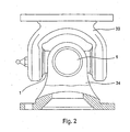
- a universal joint is shown in Fig. 2 schematically shown. Joints and cardan shafts and the Most compensating couplings are used to compensate for less Shaft misalignments.
- Fig. 2 are two joint forks 33 and 34 connected via universal joint pin.
- the joint forks 33, 34 can, for example, in Be forged joint.
- the cone cross usually exists Made of high quality case steel and is in Rolling received. It is advantageous if you long pins in terms of accurate manufacture of the sliding surfaces and friction losses used.
- Such cardan shafts can be used on axle drives of motor vehicles or rail vehicles.
- For universal joints in motor vehicle construction is considered optimal diffraction angle five to seven degrees, especially with Consideration of heating and efficiency. Too small Auslenkwinkeln there is a risk that bearing needles and pin off because of insufficient rolling movement.
- a spider is made of a cylindrical pin member 35, which by means of a Rolling elements 3 rotatably arranged in a bearing bush 2 is.
- the bearing bush 2 consists of a cylindrical housing part 36 with a bottom 8, the plane end face 17 has. At the front end of the bearing bush 2 There is an annular recess for receiving at least one first ring-shaped, outer sealing body 4, which is provided with a second inner, also annularly formed sealing body 5 via form-fitting sealing elements or sealing lamellae 9 operatively connected is.
- the two seal body 4 and 5 form substantially the main sealing system between the outer and the inner area of the bearing bush 2.
- seal body 4 also belongs the second inner, ring-shaped Seal body 5.
- Both seal body 4 and 5 have numerous juxtaposed, labyrinthine formed sealing elements or sealing lamellae 9 on, which is trapezoidal in cross section according to FIG could be.
- the sealing fins 9 are formed and arranged in such a way that between the opposite sealing surfaces a slight gap remains, so that between the two sealing bodies 4 and 5 a rotary motion is possible.
- the outer sealing body has three adjacent ones Seal plates 9, to which a cylindrical Approach 39 connects, in a corresponding in the inner sealing body 5 provided recess 40th is used in registration.
- the inside can End face of the recess 40 against the end face Press the sealing body 4 and thus the Seal body 4 in turn against the shoulder 16 of the bearing bush 2 press.
- This ensures that the two seal body 4, 5 even at a Preßverbund not further into the interior of the bearing bush 2 and thus also the position of the articular cross pin 1 can additionally secure against axial displacement.
- the second seal body 5 is with reference to its sealing blade 9 mirror image of the first Seal body 4 is formed, wherein the two opposite Seal blades 9 of FIG. 1 in one standing in constant contact.
- the seal body 5 has shown in FIG. 1 at least two with spaced apart support elements 22nd and 23, wherein the one support element 22 in a Area 14 of the Kcnusübergangs is provided.
- the area 14 is shown in FIG. 3 between the right end of the cylindrical pivot part 35 and a adjoining, widening conical part 30.
- the transition region 14 has a curved course.
- a part of the support element 22, 23 sits on the cylindrical part and a part of the support element on the widening part of the articular cross pin 1 on.
- the support element 22 closes in the direction of a Surface 41 of the cone portion 30 a chamber or recess 15 and to the second support member 23 at.
- the two sealing bodies 4, 5 may be made of an elastomeric Material made of thermoplastics such as polyolefins or be formed of a polyvinyl compound.
- the outer seal body 4 is connected to the bearing bush 2 and the inner seal body 5 with the journal cross pin 1 each applied by means of interference fit to this way, a penetration of foreign bodies in the interior to avoid the bearing bush and also one Loss of lubricant over the stomata in the area to exclude the joints.
- the outer seal body 4 can be made by cutting or cutting and then inserted into a corresponding injection mold in addition to the outer contour of the inner Sealing body 5 is recessed. Now he can inner seal body are injected, where he shrinks slightly during the cooling process. This results between the surfaces of the sealing fins 9 a labyrinth gap, so that it is ensured that the two cooperating sealing body.
- the advantageous embodiment of the two sealing body 4, 5 creates the possibility of this with appropriate Adaptation of any surface to a spider 1 apply.
- To the section height To reduce the seal body, this will be accordingly the sealing fins 9 in their cross-sectional height reduced. This gives you a space gain.
- this creates the possibility the sealing body 4 or 5 step-shaped Articulated cross pin to adapt easily.
- the reduction of space is also the internal Room for receiving the rolling elements 3 increases.
- the support element 23 is included Biasing force against the surface 41 of the cone part 30 at. This gives a perfect seal between the outer and the inner region of the articulated cross pin.
- the sealing lamellae extend 9 preferably in the radial direction, d. H. she extend approximately parallel to a transverse plane 31, the a central axis 11 intersects at a right angle. Between the mutually facing surfaces of the sealing lamellae 9 there is an air gap or labyrinth gap 10th
- the outer diameter of the outer, annular seal body 4 is constant over the entire length of the seal body.
- a projection 6 which extends into an annular space 24 provided in the second sealing body 5.
- a gradation or recess 25 with an end face 26 and a second end face 26 'is provided.
- a cladding part 7, which is fixedly connected to the inner, annular sealing body 5 extends.
- the outer diameter of the wrapping part 7 corresponds to the region of the end face 26 of the gradation of the outer diameter of the bearing bush 2.
- the projection 6 of the bearing bush 2 thus forms with the recess 25 in conjunction with the annular space 24 of the inner seal body 5 also a labyrinth seal.
- the with respect to the transverse plane 31 in approximately parallel end faces 26, 26 'of the projection 6 form with the recess 25 and also lying on a transverse plane end faces 27 and 27' of the wrapping part 7 with the annular space 24 each have an annular gap 28 and 29 respectively ,
- the outer wall of the seal body 4 has approximately the same outer diameter of the lower wall portion 43 of the recess 37.
- the projection 6 lies against the outer periphery of the seal body 5 and thus also forms a labyrinthine sealing gap 12.
- the projection 39 of the outer seal body 4 bears with its inner end face against the front end of the inner seal body 5 and presses in the position shown in FIG. 3, the seal body 4 against the shoulder 16.
- the axial fixation of the universal joint pin 1 is also effected by the abutment of the inner end face of the hinge pin 1 against the end face 17 of the bottom eighth
Applications Claiming Priority (2)
| Application Number | Priority Date | Filing Date | Title |
|---|---|---|---|
| DE10015571A DE10015571A1 (de) | 2000-03-29 | 2000-03-29 | Labyrinthdichtung für eine Gelenkkreuzwelle |
| DE10015571 | 2000-03-29 |
Publications (2)
| Publication Number | Publication Date |
|---|---|
| EP1138968A1 EP1138968A1 (de) | 2001-10-04 |
| EP1138968B1 true EP1138968B1 (de) | 2005-08-31 |
Family
ID=7636809
Family Applications (1)
| Application Number | Title | Priority Date | Filing Date |
|---|---|---|---|
| EP01107238A Expired - Lifetime EP1138968B1 (de) | 2000-03-29 | 2001-03-23 | Labyrinthdichtung für eine Gelenkkreuzwelle |
Country Status (4)
| Country | Link |
|---|---|
| US (1) | US6547668B2 (es) |
| EP (1) | EP1138968B1 (es) |
| DE (2) | DE10015571A1 (es) |
| ES (1) | ES2246952T3 (es) |
Families Citing this family (9)
| Publication number | Priority date | Publication date | Assignee | Title |
|---|---|---|---|---|
| US6964613B2 (en) * | 2002-10-24 | 2005-11-15 | Trw Inc. | Universal joint |
| US20040171427A1 (en) * | 2003-02-28 | 2004-09-02 | Wagner John Brian | U-joint face seal |
| US8630168B2 (en) * | 2003-06-23 | 2014-01-14 | Intel Corporation | Adaptive use of a transmit opportunity |
| US7512070B2 (en) * | 2003-06-23 | 2009-03-31 | Intel Corporation | Adaptive use of a transmit opportunity |
| US7695390B2 (en) * | 2006-09-18 | 2010-04-13 | Gm Global Technology Operations, Inc. | Multi-speed transmission |
| DE102009048290A1 (de) * | 2009-10-05 | 2011-04-07 | Schaeffler Technologies Gmbh & Co. Kg | Wälzlager, insbesondere Radial-Nadellager |
| CA2734901C (en) * | 2011-03-23 | 2018-05-22 | Hitek Urethane Global Ltd. | Elastomeric seal for rotating heads |
| US8506170B2 (en) * | 2011-10-12 | 2013-08-13 | Baldor Electric Company | Bearing mounted isolator seal |
| JP5912480B2 (ja) * | 2011-12-12 | 2016-04-27 | 株式会社Roki | シール部材 |
Family Cites Families (18)
| Publication number | Priority date | Publication date | Assignee | Title |
|---|---|---|---|---|
| DE8416023U1 (de) * | 1984-08-23 | FAG Kugelfischer Georg Schäfer KGaA, 8720 Schweinfurt | Dichtung aus elastischem Werkstoff für Gelenkbüchsen | |
| US3446507A (en) * | 1966-09-21 | 1969-05-27 | Gen Motors Corp | Universal joint bearing seal assembly |
| BE792674A (nl) * | 1971-12-14 | 1973-06-13 | Wavin Bv | Buisverbinding met klemring |
| US4337628A (en) * | 1980-08-20 | 1982-07-06 | Borg-Warner Corporation | Universal joint with unitary face seal and retainer assembly |
| US4377312A (en) * | 1981-03-06 | 1983-03-22 | Dana Corporation | Bearing seal |
| FR2526896B1 (fr) * | 1982-05-15 | 1986-10-10 | Skf Kugellagerfabriken Gmbh | Dispositif d'etancheite pour coussinets |
| FR2566071B1 (fr) * | 1984-06-15 | 1989-03-10 | Glaenzer Spicer Sa | Dispositif d'etancheite pour joint de cardan |
| DE3639315C1 (de) * | 1986-11-17 | 1988-04-14 | Gelenkwellenbau Gmbh | Vorrichtung zum Abdichten eines Waelzlagers,insbesondere von Lagerbuechsen eines Kreuzgelenkes |
| DE8714948U1 (es) * | 1987-11-10 | 1987-12-17 | Skf Gmbh, 8720 Schweinfurt, De | |
| DE4128179A1 (de) * | 1991-08-24 | 1993-02-25 | Skf Gmbh | Abdichtung fuer lagerbuechsen, insbesondere fuer kreuzgelenke |
| DE4131694C2 (de) | 1991-09-24 | 2000-02-17 | Schaeffler Waelzlager Ohg | Dichtungsanordnung für eine Lagerbüchse |
| US5407387A (en) * | 1993-02-12 | 1995-04-18 | The Zeller Corporation | Universal joint seal |
| DE4408831A1 (de) | 1994-03-16 | 1995-09-21 | Schaeffler Waelzlager Kg | Abdichtung für Gelenkkreuzbüchsen |
| US5626520A (en) * | 1995-06-14 | 1997-05-06 | The Zeller Corporation | Reversible universal joint seal |
| US5588915A (en) | 1995-12-26 | 1996-12-31 | Dana Corporation | Seal and seal guard assembly for universal joint |
| IT1283092B1 (it) * | 1996-06-05 | 1998-04-07 | Gkn Automotive Ag | Corredo per crociere con una disposizione di guarnizioni |
| JP3247048B2 (ja) * | 1996-08-28 | 2002-01-15 | 矢崎総業株式会社 | リップ付きゴム製品 |
| US6095925A (en) * | 1997-10-10 | 2000-08-01 | Dana Corporation | Seal assembly and seal guard for a universal joint |
-
2000
- 2000-03-29 DE DE10015571A patent/DE10015571A1/de not_active Withdrawn
-
2001
- 2001-03-23 EP EP01107238A patent/EP1138968B1/de not_active Expired - Lifetime
- 2001-03-23 DE DE50107246T patent/DE50107246D1/de not_active Expired - Lifetime
- 2001-03-23 ES ES01107238T patent/ES2246952T3/es not_active Expired - Lifetime
- 2001-03-27 US US09/818,069 patent/US6547668B2/en not_active Expired - Fee Related
Also Published As
| Publication number | Publication date |
|---|---|
| ES2246952T3 (es) | 2006-03-01 |
| DE10015571A1 (de) | 2001-10-11 |
| EP1138968A1 (de) | 2001-10-04 |
| US6547668B2 (en) | 2003-04-15 |
| US20010034270A1 (en) | 2001-10-25 |
| DE50107246D1 (de) | 2005-10-06 |
Similar Documents
| Publication | Publication Date | Title |
|---|---|---|
| EP0274584B1 (de) | Vorrichtung zum Abdichten der Lagerbüchse eines Kreuzgelenkes | |
| EP2087249B1 (de) | Wälzlageranordnung | |
| DE60109298T2 (de) | Gleitlager | |
| EP2561241B1 (de) | Dichtungsanordnung für wälzlager | |
| EP2239475B1 (de) | Gegenbahngelenk | |
| DD237535A5 (de) | Elastisches gelenk, kupplung oder dergleichen | |
| EP0330993B1 (de) | Lagerungsanordnung für ein Zapfenkreuz eines Kreuzgelenkes | |
| DE10209933B4 (de) | Gegenbahngelenk | |
| EP2391832B1 (de) | Gleichlaufdrehgelenk mit verbesserten montageeigenschaften | |
| EP1138968B1 (de) | Labyrinthdichtung für eine Gelenkkreuzwelle | |
| EP0785370A1 (de) | Kreuzgelenkanordnung für eine Gelenkwelle | |
| DE1919431A1 (de) | Waelzlageranordnung | |
| EP0577830A1 (de) | Kugelgleichlaufdrehgelenk mit käfigsicherungselementen. | |
| WO2004097239A1 (de) | Zentriervorrichtung zum gegenseitigen zentrieren zweier wellenenden | |
| DE4321986A1 (de) | Zahnkupplung, insbes. für ein Antriebsaggregat eines Schienenfahrzeugs | |
| EP1225355B1 (de) | Dichtungssystem für ein Lager eines Kreuzgelenkes | |
| DE4211757A1 (de) | Dichtungsanordnung für ein Kreuzgelenk | |
| DE2734383A1 (de) | Vorrichtung zum gegenseitigen verbinden von drehwellen | |
| EP0773379A1 (de) | Dichtungsanordnung für ein Zapfenkreuz | |
| EP2597325B1 (de) | Abgedichtete Gelenkverbindung | |
| WO2003006264A1 (de) | Lagerungsanordnung für eine antreibbare radnabe eines kraftfahrzeuges | |
| WO2024008351A1 (de) | Einführelement zum einführen und positionieren eines wellenelementes, ein verfahren zum zusammenbau eines systems sowie ein verfahren zum austausch eines bauteils in einem system | |
| DE10246755A1 (de) | Gelenkanordnung | |
| DE102018124047A1 (de) | Gelenkaußenteil für homokinetische Gelenke | |
| DE7906071U1 (de) | Wälzlager |
Legal Events
| Date | Code | Title | Description |
|---|---|---|---|
| PUAI | Public reference made under article 153(3) epc to a published international application that has entered the european phase |
Free format text: ORIGINAL CODE: 0009012 |
|
| AK | Designated contracting states |
Kind code of ref document: A1 Designated state(s): DE ES FR GB IT Kind code of ref document: A1 Designated state(s): AT BE CH CY DE DK ES FI FR GB GR IE IT LI LU MC NL PT SE TR |
|
| AX | Request for extension of the european patent |
Free format text: AL;LT;LV;MK;RO;SI |
|
| 17P | Request for examination filed |
Effective date: 20020221 |
|
| AKX | Designation fees paid |
Free format text: DE ES FR GB IT |
|
| 17Q | First examination report despatched |
Effective date: 20041103 |
|
| GRAP | Despatch of communication of intention to grant a patent |
Free format text: ORIGINAL CODE: EPIDOSNIGR1 |
|
| GRAS | Grant fee paid |
Free format text: ORIGINAL CODE: EPIDOSNIGR3 |
|
| GRAA | (expected) grant |
Free format text: ORIGINAL CODE: 0009210 |
|
| AK | Designated contracting states |
Kind code of ref document: B1 Designated state(s): DE ES FR GB IT |
|
| REG | Reference to a national code |
Ref country code: GB Ref legal event code: FG4D Free format text: NOT ENGLISH |
|
| REF | Corresponds to: |
Ref document number: 50107246 Country of ref document: DE Date of ref document: 20051006 Kind code of ref document: P |
|
| GBT | Gb: translation of ep patent filed (gb section 77(6)(a)/1977) |
Effective date: 20051005 |
|
| REG | Reference to a national code |
Ref country code: ES Ref legal event code: FG2A Ref document number: 2246952 Country of ref document: ES Kind code of ref document: T3 |
|
| ET | Fr: translation filed | ||
| PLBE | No opposition filed within time limit |
Free format text: ORIGINAL CODE: 0009261 |
|
| STAA | Information on the status of an ep patent application or granted ep patent |
Free format text: STATUS: NO OPPOSITION FILED WITHIN TIME LIMIT |
|
| 26N | No opposition filed |
Effective date: 20060601 |
|
| PGFP | Annual fee paid to national office [announced via postgrant information from national office to epo] |
Ref country code: ES Payment date: 20100326 Year of fee payment: 10 |
|
| PGFP | Annual fee paid to national office [announced via postgrant information from national office to epo] |
Ref country code: FR Payment date: 20100402 Year of fee payment: 10 Ref country code: IT Payment date: 20100327 Year of fee payment: 10 |
|
| PGFP | Annual fee paid to national office [announced via postgrant information from national office to epo] |
Ref country code: GB Payment date: 20100322 Year of fee payment: 10 |
|
| PGFP | Annual fee paid to national office [announced via postgrant information from national office to epo] |
Ref country code: DE Payment date: 20100324 Year of fee payment: 10 |
|
| GBPC | Gb: european patent ceased through non-payment of renewal fee |
Effective date: 20110323 |
|
| REG | Reference to a national code |
Ref country code: FR Ref legal event code: ST Effective date: 20111130 |
|
| PG25 | Lapsed in a contracting state [announced via postgrant information from national office to epo] |
Ref country code: DE Free format text: LAPSE BECAUSE OF NON-PAYMENT OF DUE FEES Effective date: 20111001 Ref country code: FR Free format text: LAPSE BECAUSE OF NON-PAYMENT OF DUE FEES Effective date: 20110331 |
|
| REG | Reference to a national code |
Ref country code: DE Ref legal event code: R119 Ref document number: 50107246 Country of ref document: DE Effective date: 20111001 |
|
| PG25 | Lapsed in a contracting state [announced via postgrant information from national office to epo] |
Ref country code: IT Free format text: LAPSE BECAUSE OF NON-PAYMENT OF DUE FEES Effective date: 20110323 Ref country code: GB Free format text: LAPSE BECAUSE OF NON-PAYMENT OF DUE FEES Effective date: 20110323 |
|
| REG | Reference to a national code |
Ref country code: ES Ref legal event code: FD2A Effective date: 20120424 |
|
| PG25 | Lapsed in a contracting state [announced via postgrant information from national office to epo] |
Ref country code: ES Free format text: LAPSE BECAUSE OF NON-PAYMENT OF DUE FEES Effective date: 20110324 |