EP1138968B1 - Labyrinth seal for a universal joint - Google Patents
Labyrinth seal for a universal joint Download PDFInfo
- Publication number
- EP1138968B1 EP1138968B1 EP01107238A EP01107238A EP1138968B1 EP 1138968 B1 EP1138968 B1 EP 1138968B1 EP 01107238 A EP01107238 A EP 01107238A EP 01107238 A EP01107238 A EP 01107238A EP 1138968 B1 EP1138968 B1 EP 1138968B1
- Authority
- EP
- European Patent Office
- Prior art keywords
- seal
- seal body
- sealing
- recess
- bearing bushing
- Prior art date
- Legal status (The legal status is an assumption and is not a legal conclusion. Google has not performed a legal analysis and makes no representation as to the accuracy of the status listed.)
- Expired - Lifetime
Links
Images


Classifications
-
- F—MECHANICAL ENGINEERING; LIGHTING; HEATING; WEAPONS; BLASTING
- F16—ENGINEERING ELEMENTS AND UNITS; GENERAL MEASURES FOR PRODUCING AND MAINTAINING EFFECTIVE FUNCTIONING OF MACHINES OR INSTALLATIONS; THERMAL INSULATION IN GENERAL
- F16D—COUPLINGS FOR TRANSMITTING ROTATION; CLUTCHES; BRAKES
- F16D3/00—Yielding couplings, i.e. with means permitting movement between the connected parts during the drive
- F16D3/16—Universal joints in which flexibility is produced by means of pivots or sliding or rolling connecting parts
- F16D3/26—Hooke's joints or other joints with an equivalent intermediate member to which each coupling part is pivotally or slidably connected
- F16D3/38—Hooke's joints or other joints with an equivalent intermediate member to which each coupling part is pivotally or slidably connected with a single intermediate member with trunnions or bearings arranged on two axes perpendicular to one another
- F16D3/382—Hooke's joints or other joints with an equivalent intermediate member to which each coupling part is pivotally or slidably connected with a single intermediate member with trunnions or bearings arranged on two axes perpendicular to one another constructional details of other than the intermediate member
- F16D3/385—Bearing cup; Bearing construction; Bearing seal; Mounting of bearing on the intermediate member
-
- F—MECHANICAL ENGINEERING; LIGHTING; HEATING; WEAPONS; BLASTING
- F16—ENGINEERING ELEMENTS AND UNITS; GENERAL MEASURES FOR PRODUCING AND MAINTAINING EFFECTIVE FUNCTIONING OF MACHINES OR INSTALLATIONS; THERMAL INSULATION IN GENERAL
- F16C—SHAFTS; FLEXIBLE SHAFTS; ELEMENTS OR CRANKSHAFT MECHANISMS; ROTARY BODIES OTHER THAN GEARING ELEMENTS; BEARINGS
- F16C21/00—Combinations of sliding-contact bearings with ball or roller bearings, for exclusively rotary movement
- F16C21/005—Combinations of sliding-contact bearings with ball or roller bearings, for exclusively rotary movement the external zone of a bearing with rolling members, e.g. needles, being cup-shaped, with or without a separate thrust-bearing disc or ring, e.g. for universal joints
-
- F—MECHANICAL ENGINEERING; LIGHTING; HEATING; WEAPONS; BLASTING
- F16—ENGINEERING ELEMENTS AND UNITS; GENERAL MEASURES FOR PRODUCING AND MAINTAINING EFFECTIVE FUNCTIONING OF MACHINES OR INSTALLATIONS; THERMAL INSULATION IN GENERAL
- F16C—SHAFTS; FLEXIBLE SHAFTS; ELEMENTS OR CRANKSHAFT MECHANISMS; ROTARY BODIES OTHER THAN GEARING ELEMENTS; BEARINGS
- F16C33/00—Parts of bearings; Special methods for making bearings or parts thereof
- F16C33/72—Sealings
- F16C33/76—Sealings of ball or roller bearings
- F16C33/78—Sealings of ball or roller bearings with a diaphragm, disc, or ring, with or without resilient members
- F16C33/7803—Sealings of ball or roller bearings with a diaphragm, disc, or ring, with or without resilient members suited for particular types of rolling bearings
- F16C33/7809—Sealings of ball or roller bearings with a diaphragm, disc, or ring, with or without resilient members suited for particular types of rolling bearings for needle roller bearings
-
- F—MECHANICAL ENGINEERING; LIGHTING; HEATING; WEAPONS; BLASTING
- F16—ENGINEERING ELEMENTS AND UNITS; GENERAL MEASURES FOR PRODUCING AND MAINTAINING EFFECTIVE FUNCTIONING OF MACHINES OR INSTALLATIONS; THERMAL INSULATION IN GENERAL
- F16C—SHAFTS; FLEXIBLE SHAFTS; ELEMENTS OR CRANKSHAFT MECHANISMS; ROTARY BODIES OTHER THAN GEARING ELEMENTS; BEARINGS
- F16C33/00—Parts of bearings; Special methods for making bearings or parts thereof
- F16C33/72—Sealings
- F16C33/76—Sealings of ball or roller bearings
- F16C33/80—Labyrinth sealings
-
- F—MECHANICAL ENGINEERING; LIGHTING; HEATING; WEAPONS; BLASTING
- F16—ENGINEERING ELEMENTS AND UNITS; GENERAL MEASURES FOR PRODUCING AND MAINTAINING EFFECTIVE FUNCTIONING OF MACHINES OR INSTALLATIONS; THERMAL INSULATION IN GENERAL
- F16C—SHAFTS; FLEXIBLE SHAFTS; ELEMENTS OR CRANKSHAFT MECHANISMS; ROTARY BODIES OTHER THAN GEARING ELEMENTS; BEARINGS
- F16C2361/00—Apparatus or articles in engineering in general
- F16C2361/41—Couplings
Definitions
- the invention relates to a seal for a in a bearing bush recorded joint cross pin for a universal joint shaft with an outer and an inner, annular, insertable into the bearing bush, a mutual adjustment permitting sealing body, which are in operative connection with each other.
- seal arrangement for a bearing of a journal in a bearing bush for roller bearing universal joints known, consisting of a a radial shaft seal provided with a reinforcement, the rotatably inserted into a bore of the bearing bush is and rests with a sealing lip on the pin. Furthermore, the seal arrangement has another Reinforced sealing ring in the area of an open End of the bearing bush against rotation on a shoulder arranged the pin fitting and with a bearing bush directed sealing lip is provided. The seal arrangement has a form-fitting as another component held on an outer wall of the bearing bush Sealing cap on, which with a reinforcement of the sealing ring forms a labyrinth gap.
- Sealing systems in which the main seal on a conical transition between the cylindrical rolling element surface of the articulation cross pin and the central articulated cross body takes place are known from DE 196 37 553 C1. But this can be done by a possible addition or Subtraction of production-related lengths and diameter tolerances the relevant components of the spider set the necessary bias is difficult to comply. Sealing systems of this type are due to the relative movement exposed to the respective sealing element of the friction and have an additional seal, in front of the main seal is arranged and this on the one hand from direct contact with Foreign substances protects and on the other hand increase the sealing effect should. This additional seal is on the spider appropriate. Their sealing lips are arranged that the seal on the bearing bush and on the main seal takes place.
- the invention is based on the object, the seal for a joint spigot received in a bearing bush such form and arrange that a largely permanent sealing and thus an improvement of the Lifespan is guaranteed.
- the outer seal body with the bearing bush and the inner seal body with the joint cross pin each with the aid of a press fit are connected. This will ensure that the seal between the respective sealing body and the gel pin or the bearing bush is static, d. H. the seal body does not rotate relative to the pivot pin or to the bearing book.
- a dynamic seal like the State of the art describes, although within wide limits maintenance-free, easier and cheaper, but not in the long run safe enough to meet high safety requirements to meet. Lack of lubrication can lead to a Overload of the universal joint and come to breakage.
- the sealing body one or more support elements have, wherein at least one support element as Sealing lips is formed and on the cone part or in the area of a cone transition on the articular spigot can be supported with bias.
- This ensures that the Seal no longer directly on the spider takes place, but through the interlocking, lamellar or labyrinth-shaped sealing elements, engaged with each other or in operative connection stand.
- the outer Sealing body with the bearing bush and the inner seal body connected to the spider via a press fit be such that an intrusion of foreign substances or a loss of lubricant at the joints is avoided.
- the two support elements are arranged at a distance from each other and the second support element on one of the cone transition subsequent, inclined tapered surface supportable is.
- the main seal may be different Contours and proportions of the universal joint shaft or the joint cross pin to be adapted. It is further readily possible, the height of the support elements or the lamellar sealing elements to enlarge or to shrink, so that the cross-sectional height of the main sealing area also be increased or decreased can. By reducing the total mass of the sealing elements you get a space gain and can thus without Further, the sealing elements on a step of a stepped place articulated cross pin and trained thereby the available for the WälzSystemlagerung available Enlarge space.
- Solution is finally provided that on the inner Sealing body arranged covering part a coaxial has annular space extending to a central axis, arranged to receive one on the bearing bush, annular approach is used.
- the bearing bush has a bottom with an inner Face on and between this face and the two inner end faces of the seal body are provided for receiving the joint cross pin rolling elements.
- the wrapping part and the two supporting elements form the one-piece sealing body, which consists of an elastomeric material and at least on the spider and / or on a cone part is pressed on.
- a method for producing a seal advantageous in which the outer sealing body with radial inwardly directed sealing blades machined or non-cutting produced and then in an injection mold is inserted in addition to the contour of the inner Sealing body is recessed, before injecting the inner seal body a release agent on the outer Sealing body is applied, which is the sticking together prevents the two seal body, then the inner Seal body in the contour and between the sealing lamellae injected the outer seal body and the inner seal body during the cooling process something shrinks, creating a labyrinthine gap between the two sealing bodies is formed.
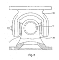
- a universal joint is shown in Fig. 2 schematically shown. Joints and cardan shafts and the Most compensating couplings are used to compensate for less Shaft misalignments.
- Fig. 2 are two joint forks 33 and 34 connected via universal joint pin.
- the joint forks 33, 34 can, for example, in Be forged joint.
- the cone cross usually exists Made of high quality case steel and is in Rolling received. It is advantageous if you long pins in terms of accurate manufacture of the sliding surfaces and friction losses used.
- Such cardan shafts can be used on axle drives of motor vehicles or rail vehicles.
- For universal joints in motor vehicle construction is considered optimal diffraction angle five to seven degrees, especially with Consideration of heating and efficiency. Too small Auslenkwinkeln there is a risk that bearing needles and pin off because of insufficient rolling movement.
- a spider is made of a cylindrical pin member 35, which by means of a Rolling elements 3 rotatably arranged in a bearing bush 2 is.
- the bearing bush 2 consists of a cylindrical housing part 36 with a bottom 8, the plane end face 17 has. At the front end of the bearing bush 2 There is an annular recess for receiving at least one first ring-shaped, outer sealing body 4, which is provided with a second inner, also annularly formed sealing body 5 via form-fitting sealing elements or sealing lamellae 9 operatively connected is.
- the two seal body 4 and 5 form substantially the main sealing system between the outer and the inner area of the bearing bush 2.
- seal body 4 also belongs the second inner, ring-shaped Seal body 5.
- Both seal body 4 and 5 have numerous juxtaposed, labyrinthine formed sealing elements or sealing lamellae 9 on, which is trapezoidal in cross section according to FIG could be.
- the sealing fins 9 are formed and arranged in such a way that between the opposite sealing surfaces a slight gap remains, so that between the two sealing bodies 4 and 5 a rotary motion is possible.
- the outer sealing body has three adjacent ones Seal plates 9, to which a cylindrical Approach 39 connects, in a corresponding in the inner sealing body 5 provided recess 40th is used in registration.
- the inside can End face of the recess 40 against the end face Press the sealing body 4 and thus the Seal body 4 in turn against the shoulder 16 of the bearing bush 2 press.
- This ensures that the two seal body 4, 5 even at a Preßverbund not further into the interior of the bearing bush 2 and thus also the position of the articular cross pin 1 can additionally secure against axial displacement.
- the second seal body 5 is with reference to its sealing blade 9 mirror image of the first Seal body 4 is formed, wherein the two opposite Seal blades 9 of FIG. 1 in one standing in constant contact.
- the seal body 5 has shown in FIG. 1 at least two with spaced apart support elements 22nd and 23, wherein the one support element 22 in a Area 14 of the Kcnusübergangs is provided.
- the area 14 is shown in FIG. 3 between the right end of the cylindrical pivot part 35 and a adjoining, widening conical part 30.
- the transition region 14 has a curved course.
- a part of the support element 22, 23 sits on the cylindrical part and a part of the support element on the widening part of the articular cross pin 1 on.
- the support element 22 closes in the direction of a Surface 41 of the cone portion 30 a chamber or recess 15 and to the second support member 23 at.
- the two sealing bodies 4, 5 may be made of an elastomeric Material made of thermoplastics such as polyolefins or be formed of a polyvinyl compound.
- the outer seal body 4 is connected to the bearing bush 2 and the inner seal body 5 with the journal cross pin 1 each applied by means of interference fit to this way, a penetration of foreign bodies in the interior to avoid the bearing bush and also one Loss of lubricant over the stomata in the area to exclude the joints.
- the outer seal body 4 can be made by cutting or cutting and then inserted into a corresponding injection mold in addition to the outer contour of the inner Sealing body 5 is recessed. Now he can inner seal body are injected, where he shrinks slightly during the cooling process. This results between the surfaces of the sealing fins 9 a labyrinth gap, so that it is ensured that the two cooperating sealing body.
- the advantageous embodiment of the two sealing body 4, 5 creates the possibility of this with appropriate Adaptation of any surface to a spider 1 apply.
- To the section height To reduce the seal body, this will be accordingly the sealing fins 9 in their cross-sectional height reduced. This gives you a space gain.
- this creates the possibility the sealing body 4 or 5 step-shaped Articulated cross pin to adapt easily.
- the reduction of space is also the internal Room for receiving the rolling elements 3 increases.
- the support element 23 is included Biasing force against the surface 41 of the cone part 30 at. This gives a perfect seal between the outer and the inner region of the articulated cross pin.
- the sealing lamellae extend 9 preferably in the radial direction, d. H. she extend approximately parallel to a transverse plane 31, the a central axis 11 intersects at a right angle. Between the mutually facing surfaces of the sealing lamellae 9 there is an air gap or labyrinth gap 10th
- the outer diameter of the outer, annular seal body 4 is constant over the entire length of the seal body.
- a projection 6 which extends into an annular space 24 provided in the second sealing body 5.
- a gradation or recess 25 with an end face 26 and a second end face 26 'is provided.
- a cladding part 7, which is fixedly connected to the inner, annular sealing body 5 extends.
- the outer diameter of the wrapping part 7 corresponds to the region of the end face 26 of the gradation of the outer diameter of the bearing bush 2.
- the projection 6 of the bearing bush 2 thus forms with the recess 25 in conjunction with the annular space 24 of the inner seal body 5 also a labyrinth seal.
- the with respect to the transverse plane 31 in approximately parallel end faces 26, 26 'of the projection 6 form with the recess 25 and also lying on a transverse plane end faces 27 and 27' of the wrapping part 7 with the annular space 24 each have an annular gap 28 and 29 respectively ,
- the outer wall of the seal body 4 has approximately the same outer diameter of the lower wall portion 43 of the recess 37.
- the projection 6 lies against the outer periphery of the seal body 5 and thus also forms a labyrinthine sealing gap 12.
- the projection 39 of the outer seal body 4 bears with its inner end face against the front end of the inner seal body 5 and presses in the position shown in FIG. 3, the seal body 4 against the shoulder 16.
- the axial fixation of the universal joint pin 1 is also effected by the abutment of the inner end face of the hinge pin 1 against the end face 17 of the bottom eighth
Landscapes
- Engineering & Computer Science (AREA)
- General Engineering & Computer Science (AREA)
- Mechanical Engineering (AREA)
- Sealing Of Bearings (AREA)
- Sealing Using Fluids, Sealing Without Contact, And Removal Of Oil (AREA)
- Sealing Devices (AREA)
- Gasket Seals (AREA)
- Rolling Contact Bearings (AREA)
- Sealing With Elastic Sealing Lips (AREA)
Description
Die Erfindung bezieht sich auf eine Abdichtung für einen in einer Lagerbuchse aufgenommenen Gelenkkreuzzapfen für eine Gelenkkreuzwelle mit einem äußeren und einem inneren, ringförmigen, in die Lagerbuchse einsetzbaren, eine gegenseitige Verstellung zulassenden Dichtungskörper, die miteinander in Wirkverbindung stehen.The invention relates to a seal for a in a bearing bush recorded joint cross pin for a universal joint shaft with an outer and an inner, annular, insertable into the bearing bush, a mutual adjustment permitting sealing body, which are in operative connection with each other.
Es ist bereits eine Dichtungsanordnung (DE 44 08 831 A1) für eine Lagerung eines Zapfens in einer Lagerbuchse für wälzgelagerte Kreuzgelenke bekannt, die aus einem mit einer Armierung versehenen Radialwellendichtring besteht, der drehfest in eine Bohrung der Lagerbuchse eingesetzt ist und mit einer Dichtlippe an den Zapfen anliegt. Ferner weist die Dichtungsanordnung einen weiteren armierten Dichtring auf, der im Bereich eines offenen Endes der Lagerbuchse drehfest an einer Schulter des Zapfens anliegend angeordnet und mit einer zur Lagerbuchse gerichteten Dichtlippe versehen ist. Die Dichtungsanordnung weist als weiteres Bauteil eine formschlüssig an einer Außenwand der Lagerbuchse gehaltene Dichtkappe auf, die mit einer Armierung des Dichtrings einen Labyrinthspalt bildet. Hierbei ist die Vorspannung der Dichtlippen, sofern sie auf einer rein zylindrischen Stufe anliegen, nur durch die Durchmessertoleranzen der betreffenden Bauteile des Gelenkkreuzsatzes beeinflußbar und kann damit eingehalten werden. Da aber aus Fertigungsgründen die Übergänge an den einzelnen Stufensprüngen abgerundet sind, werden die zylindrischen Dichtflächen in axialer Richtung verkürzt und die Möglichkeit, mehrere solche Dichtlippen hintereinander anzuordnen, um dadurch die Dichtwirkung zu verbessern, weitgehendst eingeschränkt.It is already a seal arrangement (DE 44 08 831 A1) for a bearing of a journal in a bearing bush for roller bearing universal joints known, consisting of a a radial shaft seal provided with a reinforcement, the rotatably inserted into a bore of the bearing bush is and rests with a sealing lip on the pin. Furthermore, the seal arrangement has another Reinforced sealing ring in the area of an open End of the bearing bush against rotation on a shoulder arranged the pin fitting and with a bearing bush directed sealing lip is provided. The seal arrangement has a form-fitting as another component held on an outer wall of the bearing bush Sealing cap on, which with a reinforcement of the sealing ring forms a labyrinth gap. Here is the bias the sealing lips, provided they are on a purely cylindrical Level abut, only by the diameter tolerances of relevant components of the spider set influenced and can be complied with. But there for production reasons rounded off the transitions at the individual increments are, the cylindrical sealing surfaces in axial Direction shortened and the possibility of several such To arrange sealing lips in succession, thereby the To improve sealing effect, largely limited.
Dichtungssysteme, bei denen die Hauptabdichtung auf einem konischen Übergang zwischen der zylindrischen Wälzkörperfläche des Gelenkkreuzzapfens und dem zentralen Gelenkkreuzkörper stattfindet, sind aus der DE 196 37 553 C1 bekannt. Dabei kann aber durch eine mögliche Addition bzw. Subtraktion von fertigungsbedingten Längen und Durchmessertoleranzen der betreffenden Bauteile des Gelenkkreuzsatzes die nötige Vorspannung nur erschwert eingehalten werden. Dichtungssysteme dieser Art sind aufgrund der Relativbewegung zum jeweiligen Dichtungselement der Reibung ausgesetzt und besitzen eine Zusatzdichtung, die vor der Hauptdichtung angeordnet ist und diese zum einen vor direktem Kontakt mit Fremdstoffen schützt und zum anderen die Dichtwirkung erhöhen soll. Diese Zusatzdichtung ist auf dem Gelenkkreuzzapfen angebracht. Ihre Dichtlippen sind so angeordnet, dass die Abdichtung auf der Lagerbuchse und auf der Hauptdichtung stattfindet. Sealing systems in which the main seal on a conical transition between the cylindrical rolling element surface of the articulation cross pin and the central articulated cross body takes place, are known from DE 196 37 553 C1. But this can be done by a possible addition or Subtraction of production-related lengths and diameter tolerances the relevant components of the spider set the necessary bias is difficult to comply. Sealing systems of this type are due to the relative movement exposed to the respective sealing element of the friction and have an additional seal, in front of the main seal is arranged and this on the one hand from direct contact with Foreign substances protects and on the other hand increase the sealing effect should. This additional seal is on the spider appropriate. Their sealing lips are arranged that the seal on the bearing bush and on the main seal takes place.
Ein anderes Problem beim Abdichten eines Gelenkkreuzsatzes stellt die Kontur des Gelenkkreuzes dar, denn aus Fertigungsgründen ist der Übergang zwischen der zylindrischen Wälzkörperlauffläche des Gelenkkreuzzapfens und dem zentralen Gelenkkreuzkörper konisch verrundet oder stufenförmig mit jeweils einem Konus oder Radius bzw. Stufensprung ausgebildet. Dieser Übergang zwischen Gelenkkreuzzapfen und zentralem Gelenkkreuzkörper dient als Dichtfläche der Hauptdichtung, an der eine oder mehrere Dichtlippen des Dichtungssystems, das im Regelfall ortsfest mit der Gelenkkreuzbuchse verbunden ist, mit einer bestimmten Vorspannung anliegen. Diese Vorspannung muß aus funktionstechnischen Gründen gewährleistet sein, da durch eine zu geringe Vorspannung Fremdstoffe in die Lagerung eindringen können oder durch eine zu große Vorspannung ein erhöhter Reibungsverschleiß stattfindet und somit in beiden Fällen ein frühzeitiger Lagerausfall hervorgerufen wird.Another problem with sealing a spider set represents the contour of the spider, because of manufacturing reasons is the transition between the cylindrical Wälzkörperlauffläche of the Gelenkkreuzzapfens and the central Articulated cross body conically rounded or stepped each formed with a cone or radius or increment. This transition between articular spigots and central articulated cross body serves as a sealing surface of Main seal, on which one or more sealing lips of the Sealing system, which is usually stationary with the joint cross socket connected, with a certain bias issue. This bias must be functional Reasons to be ensured because of too low a bias Foreign substances can enter the storage or too high a preload an increased friction wear takes place and thus in both cases an early one Bearing failure is caused.
Der Erfindung liegt die Aufgabe zugrunde, die Abdichtung für einen in einer Lagerbuchse aufgenommenen Gelenkkreuzzapfen derart auszubilden und anzuordnen, dass eine weitgehend dauerhafte Abdichtung und somit eine Verbesserung der Lebensdauer gewährleistet wird.The invention is based on the object, the seal for a joint spigot received in a bearing bush such form and arrange that a largely permanent sealing and thus an improvement of the Lifespan is guaranteed.
Gelöst wird die Aufgabe erfindungsgemäß dadurch, dass beide in radialer Richtung gegenüberliegende Dichtungskörper labyrinthartig angeordnete, formschlüssig ineinandergreifende Dichtungslamellen aufweisen, die sich in etwa in Richtung oder parallel zu einer rechtwinklig zur Mittelachse des Gelenkkreuzzapfens angeordneten Querebene erstrecken und eineThe object is achieved according to the invention in that both in the radial direction opposite seal body labyrinthine arranged, interlocking interlocking Have sealing lamellae, which extend approximately in the direction or parallel to a perpendicular to the central axis of the spider arranged transverse plane extend and a
Labyrinthdichtung bilden und zumindest einer der Dichtungskörper ein Umhüllungsteil aufweist, das den anderen Dichtungskörper und/oder die Lagerbuchse zumindest teilweise überlappt. Labyrinth seal form and at least one of the seal body a wrapping part comprising the other sealing body and / or the bushing at least partially overlaps.
Durch die vorteilhafte Ausbildung und Anordnung der beiden Dichtungskörper mit den in Eingriff stehenden, formschlüssigen Dichtungselementen und dem zugehörigen Umhüllungsteil wird auf kostengünstige Weise eine einfache, jedoch sehr wirkungsvolle Dichtungsvorrichtung geschaffen, mit der eine dauerhafte Abdichtung und somit eine wesentliche Verbesserung der Lebensdauer gewährleistet wird.Due to the advantageous design and arrangement of the two Sealing body with the engaged, form-fitting Seal elements and the associated enclosure part is a simple, but very cost effective way created effective sealing device, with a permanent seal and thus a significant improvement the lifetime is guaranteed.
Vorteilhaft ist es hierzu, dass der äußere Dichtungskörper mit der Lagerbuchse und der innere Dichtungskörper mit dem Gelenkkreuzzapfen jeweils mit Hilfe einer Presspassung verbunden sind. Dadurch wird erreicht, dass die Abdichtung zwischen dem jeweiligen Dichtungskörper und dem Gelenlczapfen bzw. der Lagerbuche statisch erfolgt, d. h. der Dichtungskörpers rotiert nicht relativ zu dem Gelenkzapfen bzw. zu der Lagerbuche. Eine dynamische Dichtung, wie sie der Stand der Technik beschreibt, ist zwar in weiten Grenzen wartungsfrei, einfacher und billiger, aber auf Dauer nicht sicher genug, um hohen Anforderungsansprüchen an Sicherheit gerecht zu werden. Bei mangelnde Schmierung kann es zu einer Überbelastung des Kreuzgelenks und zum Bruch kommen.It is advantageous for this purpose that the outer seal body with the bearing bush and the inner seal body with the joint cross pin each with the aid of a press fit are connected. This will ensure that the seal between the respective sealing body and the gel pin or the bearing bush is static, d. H. the seal body does not rotate relative to the pivot pin or to the bearing book. A dynamic seal, like the State of the art describes, although within wide limits maintenance-free, easier and cheaper, but not in the long run safe enough to meet high safety requirements to meet. Lack of lubrication can lead to a Overload of the universal joint and come to breakage.
Eine zusätzliche Möglichkeit ist gemäß einer Weiterbildung, dass die Dichtungskörper ein oder mehrere Abstützelemente aufweisen, wobei zumindest ein Abstützelement als Dichtlippen ausgebildet ist und auf dem Konusteil oder im Bereich eines Konusübergangs auf dem Gelenkkreuzzapfen mit Vorspannung abstützbar ist. Hierdurch wird erreicht, dass die Abdichtung nicht mehr direkt auf dem Gelenkkreuzzapfen stattfindet, sondern durch die ineinander eingreifenden, lamellenförmigen bzw. labyrinthförmig ausgebildeten Dichtungselemente, die miteinander in Eingriff bzw. in Wirkverbindung stehen. Vorteilhafterweise kann dabei der äußere Dichtungskörper mit der Lagerbuchse und der innere Dich-tungskörper mit dem Gelenkkreuz über eine Presspassung verbunden sein, so dass ein Eindringen von Fremdstoffen bzw. ein Schmiermittelverlust an den Fügestellen vermieden wird. Zur Herstellung dieses Dichtungssystems, das aus dem äußeren Dichtungskörper und dem inneren Dichtungskörper besteht, die beide ringförmig ausgebildet sind, kann der äußere Dichtungskörper spanend oder spanlos hergestellt und anschließend in eine Spritzgussform eingelegt werden, an der zusätzlich die Kontur des inneren Dichtungskörpers ausgespart ist. Hierdurch kann der innere Dichtungskörper eingespritzt werden, so daß er beim Erkaltungsvorgang etwas schrumpft. Dadurch entsteht ein Labyrinthspalt zwischen den beiden Dichtungskörpern, der sicherstellt, daß sich Innen- und Außenringe gegeneinander drehen lassen können, ohne daß große Reibungsverluste auftreten. Vor dem Einspritzen des inneren Dichtungskörpers wird durch Aufbringen von Trennmittel auf den beiden Dichtungskörpern verhindert, daß diese zusammenhaften. Dabei ist es vorteilhaft, daß die einander gegenüberliegenden Flächen keine Unebenheiten aufweisen, wodurch ebenfalls Reibungsverluste reduziert werden können.An additional possibility is according to a development, that the sealing body one or more support elements have, wherein at least one support element as Sealing lips is formed and on the cone part or in the area of a cone transition on the articular spigot can be supported with bias. This ensures that the Seal no longer directly on the spider takes place, but through the interlocking, lamellar or labyrinth-shaped sealing elements, engaged with each other or in operative connection stand. Advantageously, while the outer Sealing body with the bearing bush and the inner seal body connected to the spider via a press fit be such that an intrusion of foreign substances or a loss of lubricant at the joints is avoided. To manufacture this sealing system, that of the outer Seal body and the inner seal body consists, which are both annular, the outer Sealing body made by cutting or without cutting and then be placed in an injection mold on the additional the contour of the inner seal body is recessed. As a result, the inner seal body injected so that he does something during the cooling process shrinking. This creates a labyrinth gap between the two sealing bodies, which ensures that Inner and outer rings can be turned against each other, without major friction losses occur. Before the Injection of the inner seal body is by applying of release agent on the two sealing bodies prevents them from sticking together. It is advantageous that the opposing surfaces have no bumps, which also friction losses can be reduced.
Ferner ist es vorteilhaft, daß die beiden Abstützelemente mit Abstand zueinander angeordnet sind und das zweite Abstützelement auf einer an den Konusübergang anschließenden, geneigt verlaufenden Konusfläche abstützbar ist. Durch die vorteilhafte Verwendung der beiden mit Abstand zueinander angeordneten Abstützelemente lassen sich diese ohne weiteres im Übergangsbereich zwischen dem zylinderförmigen Teil des Gelenkkreuzzapfens und dem Konusübergang auf der Oberfläche des Gelenkkreuzzapfens anbringen und dadurch auch eine einwandfreie Dichtung erzielen, insbesondere dann, wenn diese mit Vorspannung gegen die Oberfläche des Gelenkkreuzzapfens gepreßt werden.Furthermore, it is advantageous that the two support elements are arranged at a distance from each other and the second support element on one of the cone transition subsequent, inclined tapered surface supportable is. By the advantageous use of the two with Leave spaced supporting elements These are easily in the transition area between the cylindrical part of the joint cross pin and the Cone junction on the surface of the articular cross pin attach and thus a perfect seal achieve, especially if this with bias pressed against the surface of the journal cross pin.
Vorteilhaft ist es auch, daß zwischen den beiden Abstützelementen eine zur Oberfläche des Gelenkkreuzzapfens gerichtete Kammer bzw. Aussparung gebildet ist. Durch die unterschiedlich große Anzahl der Dichtungslamellen bzw. der Abstützelemente, die als Dichtungslamellen fungieren, kann die Hauptdichtung unterschiedlichen Konturen und Verhältnissen an der Gelenkkreuzwelle bzw. dem Gelenkkreuzzapfen angepaßt werden. Ferner ist es ohne weiteres möglich, die Höhe der Abstützelemente bzw. der lamellenförmigen Dichtungselemente zu vergrößern oder zu verkleinern, so dass die Querschnittshöhe des Hauptdichtungsbereichs ebenfalls vergrößert bzw. vermindert werden kann. Durch die Verminderung der Gesamtmasse der Dichtungselemente erhält man einen Bauraumgewinn und kann somit ohne weiteres die Dichtungselemente auf einer Stufe eines stufenförmig ausgebildeten Gelenkkreuzzapfens plazieren und dadurch den für die Wälzkörperlagerung zur Verfügung stehenden Bauraum vergrößern.It is also advantageous that between the two support elements one to the surface of the articular cross pin directed chamber or recess is formed. Due to the different numbers of sealing lamellae or the supporting elements, as sealing lamellae The main seal may be different Contours and proportions of the universal joint shaft or the joint cross pin to be adapted. It is further readily possible, the height of the support elements or the lamellar sealing elements to enlarge or to shrink, so that the cross-sectional height of the main sealing area also be increased or decreased can. By reducing the total mass of the sealing elements you get a space gain and can thus without Further, the sealing elements on a step of a stepped place articulated cross pin and trained thereby the available for the Wälzkörperlagerung available Enlarge space.
Gemäß einer bevorzugten Ausführungsform der erfindungsgemäßen Lösung ist schließlich vorgesehen, dass das auf dem inneren Dichtungskörper angeordnete Umhüllungsteil einen koaxial zu einer Mittelachse verlaufenden Ringraum aufweist, der zur Aufnahme eines an der Lagerbuchse angeordneten, ringförmigen Ansatzes dient.According to a preferred embodiment of the invention Solution is finally provided that on the inner Sealing body arranged covering part a coaxial has annular space extending to a central axis, arranged to receive one on the bearing bush, annular approach is used.
Von besonderer Bedeutung ist für die vorliegende Erfindung, dass der Ansatz eine im Querschnitt rechteckförmige Aussparung aufweist, in die der äußere Teil des Umhüllungsteils einbringbar ist und der Ansatz und die Aussparung mit dem Ringraum eine Labyrinthdichtung bilden.Of particular importance for the present invention, that the approach in a rectangular cross-section Has recess into which the outer part of the wrapping part is einbringbar and the approach and the recess with the annular space form a labyrinth seal.
Dabei weist die Lagerbuchse einen Boden mit einer innenliegenden Stirnfläche auf und zwischen dieser Stirnfläche und den beiden innenliegenden Stirnflächen der Dichtungskörper sind zur Aufnahme des Gelenkkreuzzapfens Wälzkörper vorgesehen.In this case, the bearing bush has a bottom with an inner Face on and between this face and the two inner end faces of the seal body are provided for receiving the joint cross pin rolling elements.
Durch das vorteilhaft beschriebene Dichtungssystem erhält man eine zusätzliche Abdichtung durch eine am Innenring des Dichtungskörpers angeformte Dichtlippe in Verbindung mit dem Gelenkkreuzkonus. Durch den Presssitz des inneren Dichtungskörpers auf dem Gelenkkreuzzapfen können Fremdkörper nicht in den Innenraum der Lagerbuchse eindringen. Durch den Überlappungs- bzw. Umhüllungsteil, der den anderen Dichtungskörper und/oder die Lagerbuchse zumindest teilweise umgibt, entsteht eine zusätzliche Abdichtung, die einerseits die labyrinthförmig ausgebildete Hauptdichtung und andererseits den Pressverband zwischen Außenring und Lagerbuchse vor Fremdstoffen in vorteilhafter Weise schützt. Durch die Aussparung zwischen den beiden Abstütz- oder Dichtungselementen kann der Anpressdruck in diesem Bereich optimal gesteuert werden. Ferner kann in diese Aussparung ein aus Elastomere bestehender Ring eingelegt und somit eine zusätzliche Dichtwirkung erreicht werden.Obtained by the advantageous described sealing system one additional seal by one on the inner ring of the Sealing body molded sealing lip in conjunction with the articular cross cone. By the interference fit of the inner seal body on the spider can foreign matter do not penetrate into the interior of the bearing bush. By the overlapping part of the other Sealing body and / or the bearing bush at least partially surrounds, creates an additional seal, on the one hand the labyrinth-shaped main seal and on the other hand, the interference fit between outer ring and bearing bush protects against foreign substances in an advantageous manner. Through the recess between the two support or Sealing elements can be the contact pressure in this area be optimally controlled. Furthermore, in this recess a ring made of elastomers inserted and thus a additional sealing effect can be achieved.
Im Zusammenhang mit der erfindungsgemäßen Ausbildung und Anordnung ist es von Vorteil, dass mit Bezug auf eine Querebene in etwa parallel verlaufende Stirnseiten des Ansatzes und der Aussparung mit ebenfalls auf einer Querebene liegenden Stirnseiten des Umhüllungsteils des Ringraums je einen Ringspalt bilden. Durch die vorteilhafte Materialauswahl und Dimensionierung, die beide direkten Einfluß auf die einzelnen Pressverbände haben, kann die Größe des Labyrinthspalts gesteuert und dadurch der Vorteil erreicht werden, dass die hauptsächliche Dichtwirkung nur von den Durchmessertoleranzen beeinflußt wird. Sowohl der äußere als auch der innere Dichtungskörper werden bei der Montage auf ihre jeweiligen Bauteile aufgepresst und im elastischen Bereich verformt. Hierbei kann sich der Labyrinthspalt des Dichtungssystems wieder verkleinern. Durch die vorteilhafte Auswahl dieser Einflußgrößen kann die Reibung zwischen dem inneren und dem äußeren Dichtungskörper auf ein Minimum reduziert werden, und man erhält dadurch eine weitgehend verschleißfreie Abdichtung.In connection with the embodiment of the invention and Arrangement, it is advantageous that with respect to a transverse plane approximately parallel end faces of the approach and the recess also lying on a transverse plane Front sides of the wrapping part of the Annular space each form an annular gap. By the advantageous Material selection and sizing, both direct The influence on the individual press federations can have Size of the labyrinth gap controlled and thereby the advantage be achieved that the main sealing effect only is affected by the diameter tolerances. Both the Outer and the inner seal body are in the Assembly pressed on their respective components and in the elastic Area deformed. This can be the labyrinth gap reduce the sealing system again. By the advantageous selection of these influencing variables can be the friction between the inner and outer seal body be reduced to a minimum, and you get by a largely wear-free seal.
Vorteilhaft ist es ferner, dass das Umhüllungsteil und die beiden Abstützelemente den einteiligen Dichtungskörper bilden, der aus einem elastomeren Werkstoff besteht und zumindest auf den Gelenkkreuzzapfen und/oder auf ein Konusteil aufgepresst ist.It is also advantageous that the wrapping part and the two supporting elements form the one-piece sealing body, which consists of an elastomeric material and at least on the spider and / or on a cone part is pressed on.
Hierzu ist ein Verfahren zur Herstellung einer Abdichtung von Vorteil, bei dem der äußere Dichtungskörper mit radial nach innen gerichteten Dichtungslamellen spanend oder spanlos hergestellt und anschließend in eine Spritzgussform eingelegt wird an der zusätzlich die Kontur des inneren Dichtungskörpers ausgespart ist, vor dem Einspritzen des inneren Dichtungskörpers ein Trennmittel auf den äußeren Dichtungskörper aufgebracht wird, welches das Zusammenhaften der beiden Dichtungskörper verhindert, danach der innere Dichtungskörper in die Kontur und zwischen die Dichtungslamellen des äußeren Dichtungskörpers eingespritzt wird und der innere Dichtungskörper beim Erkaltungsvorgang etwas schrumpft, wodurch ein Labyrinthspalt zwischen den beiden Dichtungskörpern gebildet wird.For this purpose, a method for producing a seal advantageous in which the outer sealing body with radial inwardly directed sealing blades machined or non-cutting produced and then in an injection mold is inserted in addition to the contour of the inner Sealing body is recessed, before injecting the inner seal body a release agent on the outer Sealing body is applied, which is the sticking together prevents the two seal body, then the inner Seal body in the contour and between the sealing lamellae injected the outer seal body and the inner seal body during the cooling process something shrinks, creating a labyrinthine gap between the two sealing bodies is formed.
Weitere Vorteile und Einzelheiten der Erfindung sind in den Patentansprüchen und in der Beschreibung erläutert und in den Figuren dargestellt. Es zeigt:
Figur 1- eine Abdichtung für einen in einer Lagerbuchse aufgenommenen Gelenkkreuzzapfen für eine Gelenkkreuzwelle mit einem äußeren und einem inneren, ringförmigen, in die Lagerbuchse einsetzbaren Dichtungskörper,
Figur 2- eine schematische Darstellung eines Kreuzgelenks, teilweise im Schnitt,
- Figur 3
- eine vergrößerte Darstellung der beiden
in
Figur 1 dargestellten Dichtungskörper mit dem Konusbereich des Gelenkkreuzzapfens.
- FIG. 1
- a seal for a joint spigot received in a bearing bush for a universal joint shaft with an outer and an inner, annular sealing body which can be inserted into the bearing bush,
- FIG. 2
- a schematic representation of a universal joint, partly in section,
- FIG. 3
- an enlarged view of the two seal body shown in Figure 1 with the cone region of the joint cross pin.
In der Zeichnung ist in Fig. 2 ein Kreuzgelenk schematisch
dargestellt. Gelenke und Gelenkwellen sowie die
meisten Ausgleichskupplungen dienen zum Ausgleich geringer
Wellenverlagerungen. Am meisten verwendet man das
Kreuzgelenk (Kardangelenk). In Fig. 2 sind zwei Gelenkgabeln
33 und 34 über Kreuzgelenkzapfen miteinander verbunden.
Die Gelenkgabeln 33, 34 können beispielsweise im
Gelenk geschmiedet sein. Das Zapfenkreuz besteht normalerweise
aus hochwertigem Einsatzstahl und ist in
Wälzlagern aufgenommen. Vorteilhaft ist es, wenn man
lange Zapfen in Bezug auf genaue Herstellung der Gleitflächen
und Reibungsverluste verwendet. Derartige Gelenkwellen
können bei Achsantrieben von Kraftfahrzeugen
oder Schienenfahrzeugen eingesetzt werden. Für Kreuzgelenke
im Kraftfahrzeugbau wird als optimaler Beugungswinkel
fünf bis sieben Grad angegeben, insbesondere mit
Rücksicht auf Erwärmung und Wirkungsgrad. Bei zu kleinen
Auslenkwinkeln besteht die Gefahr, daß sich Lagernadeln
und Zapfen wegen zu geringer Wälzbewegung abplatten.In the drawing, a universal joint is shown in Fig. 2 schematically
shown. Joints and cardan shafts and the
Most compensating couplings are used to compensate for less
Shaft misalignments. The most used one
Universal joint (cardan joint). In Fig. 2 are two
Ein besonderes Problem ist die einwandfreie Abdichtung
des Gelenkkreuzzapfens, der in Fig. 1 und 3 schematisch
wiedergegeben ist. Ein Gelenkkreuzzapfen besteht aus
einem zylinderförmigen Zapfenteil 35, das mittels eines
Wälzkörpers 3 in einer Lagerbuchse 2 drehbar angeordnet
ist.A special problem is the perfect seal
of the articulated cross pin, the in Figs. 1 and 3 schematically
is reproduced. A spider is made of
a
Die Lagerbuchse 2 besteht aus einem zylinderförmigen Gehäuseteil
36 mit einem Boden 8, der eine plane Stirnfläche
17 aufweist. Am stirnseitigen Ende der Lagerbuchse 2
befindet sich eine ringförmige Aussparung zur Aufnahme
von mindestens einem ersten ringförmig ausgebildeten,
äußeren Dichtungskörper 4, der mit einem zweiten innenliegenden,
ebenfalls ringförmig ausgebildeten Dichtungskörper
5 über formschlüssig ausgebildete Dichtungselemente
bzw. Dichtungslamellen 9 wirkungsmäßig verbunden
ist. Die beiden Dichtungskörper 4 und 5 bilden im wesentlichen
das Hauptabdichtungssystem zwischen dem Außen-
und dem Innenbereich der Lagerbuchse 2.The bearing
Zwischen der Stirnfläche 17 und zwei ebenfalls gegenüberliegenden
Stirnflächen 38 der Dichtungskörper 4, 5
befindet sich der bereits erwähnte Wälzkörper 3 zur Lagerung
des Gelenkzapfenteils 35 des Gelenkkreuzzapfens
1. Dieser Innenraum wird durch die beiden Dichtungskörper
4 und 5 auf vorteilhafte Weise unter Vermeidung
großer Reibungskrafte gegenüber Fremdkörpern abgedichtet.Between the
In einer ringförmigen Aussparung 37, die durch eine
Schulter 16 begrenzt wird, sitzt der bereits erwähnte
erste Dichtungskörper 4, der in die ringförmige Aussparung
37 eingepreßt werden kann, um eine gute Reibschlußverbindung
zwischen der Innenoberfläche des Dichtungskörpers
4 und der Innenoberfläche der Aussparung sicherzustellen.In an
Zu dem ersten äußeren, ringförmigen Dichtungskörper 4
gehört auch der zweite innere, ringförmig ausgebildete
Dichtungskörper 5. Beide Dichtungskörper 4 und 5 weisen
zahlreiche nebeneinander angeordnete, labyrinthartig
ausgebildete Dichtungselemente bzw. Dichtungslamellen 9
auf, die im Querschnitt gemäß Fig. 3 trapezförmig ausgebildet
sein können.To the first outer annular seal body. 4
also belongs the second inner, ring-shaped
Die Dichtungslamellen 9 sind derart ausgebildet und angeordnet,
daß zwischen den gegenüberliegenden Dichtungsflächen
ein geringfügiger Spalt verbleibt, so daß zwischen
den beiden Dichtungskörpern 4 und 5 eine Drehbewegung
möglich ist. Im Ausführungsbeispiel gemäß Fig. 3
weist der äußere Dichtungskörper drei nebeneinanderliegende
Dichtungslamellen 9 auf, an die sich ein zylinderförmiger
Ansatz 39 anschließt, der in eine entsprechende
im inneren Dichtungskörper 5 vorgesehene Ausdrehung 40
paßgenau eingesetzt ist. Auf diese Weise kann die innenliegende
Stirnfläche der Ausdrehung 40 gegen die Stirnfläche
des Dichtungskörpers 4 drücken und somit den
Dichtungskörper 4 wiederum gegen die Schulter 16 der Lagerbuchse
2 pressen. Hierdurch wird sichergestellt, daß
die beiden Dichtungskörper 4, 5 auch bei einem Preßverbund
nicht weiter in den Innenraum der Lagerbuchse 2
wandern und somit auch die Lage des Gelenkkreuzzapfens 1
gegen eine axiale Verschiebung zusätzlich sichern können.
Der zweite Dichtungskörper 5 ist mit Bezug auf
seine Dichtungslamelle 9 spiegelbildlich zu dem ersten
Dichtungskörper 4 ausgebildet, wobei die beiden gegenüberliegenden
Dichtungslamellen 9 gemäß Fig. 1 in einem
ständigen Eingriff stehen.The sealing
Der Dichtungskörper 5 weist gemäß Fig. 1 wenigstens zwei
mit Abstand zueinander angeordnete Abstützelemente 22
und 23 auf, wobei das eine Abstützelement 22 in einem
Bereich 14 des Kcnusübergangs vorgesehen ist. Der Bereich
14 liegt gemäß Fig. 3 zwischen dem rechten Ende
des zylindrischen Gelenkzapfenteils 35 und einem sich
daran anschließenden, sich erweiternden Konusteil 30.
Der Übergangsbereich 14 hat einen kurvenförmigen Verlauf.
Ein Teil des Abstützelements 22, 23 sitzt auf dem
zylindrischen Teil und ein Teil des Abstützelements auf
dem sich erweiternden Teil des Gelenkkreuzzapfens 1 auf.
An das Abstützelement 22 schließt sich in Richtung einer
Oberfläche 41 des Konusteils 30 eine Kammer bzw. Aussparung
15 und daran das zweite Abstützelement 23 an.The
Die beiden Dichtungskörper 4, 5 können aus einem elastomeren
Material, aus Thermoplasten wie Polyolefine oder
aus einer Polyvinylverbindung gebildet sein.The two sealing
Der äußere Dichtungskörper 4 wird mit der Lagerbuchse 2
und der innere Dichtungskörper 5 mit dem Gelenkkreuzzapfen
1 jeweils mittels Preßpassung aufgebracht, um auf
diese Weise ein Eindringen von Fremdkörpern in den Innenraum
der Lagerbuchse zu vermeiden und auch einen
Schmiermittelverlust über die Spaltöffnungen im Bereich
der Fügestellen auszuschließen. Bei der Herstellung der
Dichtungsvorrichtung werden die beiden Dichtungskörper 4
und 5 vor dem Einbau zusammengesetzt. Der äußere Dichtungskörper
4 kann spanend oder spanlos gefertigt und
anschließend in eine entsprechende Spritzgußform eingelegt
werden, an der zusätzlich die Außenkontur des inneren
Dichtungskörpers 5 ausgespart ist. Jetzt kann der
innere Dichtungskörper eingespritzt werden, wobei er
beim Erkaltungsvorgang etwas schrumpft. Hierdurch entsteht
zwischen den Oberflächen der Dichtungslamellen 9
ein Labyrinthspalt, so daß sichergestellt wird, daß die
beiden miteinander zusammenwirkenden Dichtungskörper 4
und 5 gegeneinander gedreht werden können. Vorteilhafterweise
wird vor dem Einspritzvorgang des inneren Dichtungskörpers
5 Trennmittel auf die Oberfläche des äußeren
Dichtungskörpers 4 gebracht, damit die Dichtungslamellen
nicht zusammenhaften. Vorteilhaft ist es
hierzu, wenn die Dichtungsflächen eine sehr geringe
Rauhtiefe aufweisen, um bei einer gegenseitigen Verstellung
der Dichtungskörper 4 und 5 die Reibungsverluste klein zu
halten.The
Die vorteilhafte Ausgestaltung der beiden Dichtungskörper
4, 5 schafft die Möglichkeit, diese bei entsprechender
Anpassung jeder beliebigen Oberfläche auf einen Gelenkkreuzzapfen
1 aufzubringen. Um die Querschnittshöhe
der Dichtungskörper zu verringern, werden hierzu entsprechend
die Dichtungslamellen 9 in ihrer Querschnittshöhe
reduziert. Hierdurch erhält man einen Bauraumgewinn.
Ferner wird hierdurch die Möglichkeit geschaffen,
die Dichtungskörper 4 bzw. 5 stufenförmig ausgebildeten
Gelenkkreuzzapfen ohne weiteres anzupassen. Durch
die Verringerung des Bauraums wird auch der innenliegende
Raum zur Aufnahme der Wälzkörper 3 vergrößert.The advantageous embodiment of the two sealing
In vorteilhafter Weise liegt das Abstützelement 23 mit
Vorspannkraft gegen die Oberfläche 41 des Konusteils 30
an. Hierdurch erhält man eine einwandfreie Abdichtung
zwischen dem Außen- und dem Innenbereich des Gelenkkreuzzapfens.Advantageously, the
Wie aus Fig. 1 hervorgeht, erstrecken sich die Dichtungslamellen
9 vorzugsweise in radialer Richtung, d. h. sie
erstrecken sich in etwa parallel zu einer Querebene 31, die
eine Mittelachse 11 in einem rechten Winkel schneidet. Zwischen
den einander zugewandten Oberflächen der Dichtungslamellen
9 befindet sich ein Luftspalt bzw. Labyrinthspalt
10.As is apparent from Fig. 1, the sealing lamellae extend
9 preferably in the radial direction, d. H. she
extend approximately parallel to a
Der Außendurchmesser des äußeren, ringförmig ausgebildeten
Dichtungskörpers 4 ist über die gesamte Länge des Dichtungskörpers
konstant. Am Ende der Lagerbuchse 2 befindet
sich ein Ansatz 6, der sich in einen im zweiten Dichtungskörper
5 vorgesehenen Ringraum 24 erstreckt. Am stirnseitigen
Ende der Lagerbuchse 2 ist eine Abstufung bzw. Aussparung
25 mit einer Stirnseite 26 und einer zweiten Stirnseite
26' vorgesehen. In diese Abstufung bzw. Aussparung 25
erstreckt sich ein Umhüllungsteil 7, das fest mit dem inneren,
ringförmigen Dichtungskörper 5 verbunden ist. Der
Außendurchmesser des Umhüllungsteils 7 entspricht dem
Bereich der Stirnseite 26 der Abstufung des
Außendurchmessers der Lagerbuchse 2. Der Ansatz 6 der
Lagerbuchse 2 bildet also mit der Aussparung 25 in
Verbindung mit dem Ringraum 24 des inneren
Dichtungskörpers 5 ebenfalls eine Labyrinthdichtung. Die
mit Bezug auf die Querebene 31 in etwa parallel verlaufenden
Stirnseiten 26, 26' des Ansatzes 6 bilden mit der
Aussparung 25 und die ebenfalls auf einer Querebene liegenden
Stirnseiten 27 und 27' des Umhüllungsteils 7 mit dem
Ringraum 24 je einen Ringspalt 28 bzw. 29.
Die Außenwand des Dichtungskörpers 4 hat in etwa den gleichen
Außendurchmesser des unteren Wandteils 43 der Aussparung
37. Der Ansatz 6 liegt gegen den Außenumfang des Dichtungskörpers
5 und bildet somit ebenfalls einen labyrinthartigen
Dichtungsspalt 12. Das Umhüllungsteil 7 und die
beiden Abstützelemente 22 und 23, die, wie bereits erwähnt,
als Dichtungskörper 5 fungieren, bilden einen einteiligen
Dichtungskörper, der auf das Konusteil 30 aufgepresst ist.
Der Ansatz 39 des äußeren Dichtungskörpers 4 liegt mit seiner
innenliegenden Stirnseite gegen das stirnseitige Ende
des inneren Dichtungskörpers 5 an und presst in der Stellung
gemäß Fig. 3 den Dichtungskörper 4 gegen die Schulter
16. Damit ist auch die Axialbewegung des Gelenkkreuzzapfens
1 in Richtung des Bodens 8 der Lagerbuchse 2 begrenzt. Die
axiale Fixierung des Gelenkkreuzzapfens 1 erfolgt auch
durch die Anlage der innenliegenden Stirnfläche des Gelenkbolzens
1 gegen die Stirnfläche 17 des Bodens 8. The outer diameter of the outer,
The outer wall of the
- 11
- GelenkkreuzzapfenJointed cross pin
- 22
- Lagerbuchsebearing bush
- 33
- Wälzkörperrolling elements
- 44
- Dichtungskörper, äußererSealing body, outer
- 55
- Dichtungskörper, innererSealing body, inner
- 66
- Ansatzapproach
- 77
- Umhüllungsteilenveloping part
- 88th
- Bodenground
- 99
- Dichtungslamelle, DichtungselementSealing lamella, sealing element
- 1010
- Labyrinthspaltlabyrinth gap
- 1111
- Mittelachsecentral axis
- 1212
- Dichtungsspaltseal gap
- 1313
- Dichtlippesealing lip
- 1414
- Bereich des KonusübergangsArea of the cone junction
- 1515
- Kammer, AussparungChamber, recess
- 1616
- Schultershoulder
- 1717
- Stirnflächeface
- 1818
- LamellenteilkreisSlats pitch
- 1919
- Wälzkörper-LaufflächeRolling element bearing surface
- 2020
- Nasenose
- 21 2221 22
- Abstützelementsupporting
- 2323
- Abstützelementsupporting
- 2424
- Ringraumannulus
- 2525
- Aussparung, AbstufungRecess, gradation
- 2626
- Stirnseitefront
- 2626
- Stirnseitenfront sides
- 2727
- Stirnseite front
- 27'27 '
- Stirnseitefront
- 2828
- Ringspaltannular gap
- 2929
- Ringspaltannular gap
- 3030
- Konusteilconical part
- 3131
- Querebenetransverse plane
- 3232
- Stirnflächeface
- 3333
- Gelenkgabelyoke
- 3434
- Gelenkgabelyoke
- 3535
- GelenkzapfenteilKnuckle part
- 3636
- Gehäuseteilhousing part
- 3737
- ringförmige Aussparungannular recess
- 3838
- Stirnflächeface
- 3939
- Ansatzapproach
- 4040
- Ausdrehungrecess
- 4141
- Oberflächesurface
- 4242
- Stirnseitefront
- 4343
- Wandteilwall part
Claims (10)
- Seal for a spider trunnion (1) for a spider shaft, said trunnion (1) being received in a bearing bushing (2), said seal having an outer and an inner annular seal body (4, 5), wherein the two bodies (4, 5) interact, can be inserted in the bearing bushing (2), and permit mutual displacement,
characterized in thata) both radially opposing seal bodies (4, 5) comprise sealing lamellas (9) that are arranged like a labyrinth, engage each other with positive fit, extend approximately towards or parallel to a transverse plane (31) arranged at right angles to the center line (11) of the spider trunnion (1), and form a labyrinth seal; andb) at least one seal body (5) comprises a sheath part (7) that at least partially overlaps the other seal body (4) and/or the bearing bushing (2). - Seal according to claim 1, characterized in that the connection of the outer seal body (4) to the bearing bushing (2) as well as of the inner seal body (5) to the spider trunnion (1) is provided by way of interference fit.
- Seal according to claim 1 or 2, characterized in that the seal bodies (4, 5) comprise one or more supporting elements (22, 23), wherein at least one supporting element (22) is formed as a sealing lip and can be supported with prestress against the cone part (30) or against the spider trunnion (1) in the area of a cone transition portion (14).
- Seal according to claim 3, characterized in that the two supporting elements (22, 23) are spaced apart and that the second supporting element (23) can be supported against a slanting cone surface that is arranged adjacent to the cone transition portion (14).
- Seal according to any one of claims 3 and 4, characterized in that a chamber or recess (15) is formed between the two supporting elements (22, 23), said chamber or recess (15) being directed towards the surface of the spider trunnion (1).
- Seal according to any one of claims 1 to 5, characterized in that the sheath part (7) arranged on the inner seal body (5) comprises an annular space (24) extending coaxially to a center line (11), said annular space (24) serving to receive an annular extension piece (6) that is arranged at the bearing bushing (2).
- Bearing bushing with a seal according to claim 6, characterized in that the extension piece (6) comprises a recess (25) of rectangular cross-section for receiving the outer part of the sheath part (7) and that the extension piece (6) and the recess (25) form a labyrinth seal together with the annular space (24).
- Bearing bushing according to claim 7, characterized in that front sides (26, 26') of the extension piece (6) and of the recess (25) extending approximately parallel to the transverse plane (31) form one annular gap (28, 29) each together with front sides (27, 27') of the sheath part (7) of the annular space (24) that also lie in a transverse plane.
- Seal according to any one of claims 3 to 6, characterized in that the sheath part (7) and the two supporting elements (22, 23) form the one-piece seal body (5) that consists of an elastomer and is pressed at least onto the spider trunnion (1) and/or a cone part (30).
- Method for manufacturing a seal according to claim 1,
characterized in thata) the outer seal body (4) with radially inwardly directed sealing lamellas (9) is manufactured by material removal or by forming and then placed in an injection mould that also comprises a recess for the contour of the inner seal body (5);b) a release agent is deposited on the outer seal body (4) prior to injecting the inner seal body (5) for preventing the two seal bodies (4, 5) from sticking to each other;c) the inner seal body (5) is injected into the contour and between the sealing lamellas (9) of the outer seal body (4);d) the inner seal body (5) slightly shrinks during cooling down, thereby forming a labyrinth gap between the two seal bodies (4, 5).
Applications Claiming Priority (2)
| Application Number | Priority Date | Filing Date | Title |
|---|---|---|---|
| DE10015571A DE10015571A1 (en) | 2000-03-29 | 2000-03-29 | Labyrinth seal for pivot pin of universal joint shaft has seal bodies with positive interlocking sealing elements and overlapping jacket part |
| DE10015571 | 2000-03-29 |
Publications (2)
| Publication Number | Publication Date |
|---|---|
| EP1138968A1 EP1138968A1 (en) | 2001-10-04 |
| EP1138968B1 true EP1138968B1 (en) | 2005-08-31 |
Family
ID=7636809
Family Applications (1)
| Application Number | Title | Priority Date | Filing Date |
|---|---|---|---|
| EP01107238A Expired - Lifetime EP1138968B1 (en) | 2000-03-29 | 2001-03-23 | Labyrinth seal for a universal joint |
Country Status (4)
| Country | Link |
|---|---|
| US (1) | US6547668B2 (en) |
| EP (1) | EP1138968B1 (en) |
| DE (2) | DE10015571A1 (en) |
| ES (1) | ES2246952T3 (en) |
Families Citing this family (9)
| Publication number | Priority date | Publication date | Assignee | Title |
|---|---|---|---|---|
| US6964613B2 (en) * | 2002-10-24 | 2005-11-15 | Trw Inc. | Universal joint |
| US20040171427A1 (en) * | 2003-02-28 | 2004-09-02 | Wagner John Brian | U-joint face seal |
| US7512070B2 (en) * | 2003-06-23 | 2009-03-31 | Intel Corporation | Adaptive use of a transmit opportunity |
| US8630168B2 (en) * | 2003-06-23 | 2014-01-14 | Intel Corporation | Adaptive use of a transmit opportunity |
| US7695390B2 (en) * | 2006-09-18 | 2010-04-13 | Gm Global Technology Operations, Inc. | Multi-speed transmission |
| DE102009048290A1 (en) * | 2009-10-05 | 2011-04-07 | Schaeffler Technologies Gmbh & Co. Kg | Rolling bearings, in particular radial needle roller bearings |
| CA2734901C (en) * | 2011-03-23 | 2018-05-22 | Hitek Urethane Global Ltd. | Elastomeric seal for rotating heads |
| US8506170B2 (en) * | 2011-10-12 | 2013-08-13 | Baldor Electric Company | Bearing mounted isolator seal |
| JP5912480B2 (en) * | 2011-12-12 | 2016-04-27 | 株式会社Roki | Seal member |
Family Cites Families (18)
| Publication number | Priority date | Publication date | Assignee | Title |
|---|---|---|---|---|
| DE8416023U1 (en) * | 1984-08-23 | FAG Kugelfischer Georg Schäfer KGaA, 8720 Schweinfurt | Seal made of elastic material for joint sleeves | |
| US3446507A (en) * | 1966-09-21 | 1969-05-27 | Gen Motors Corp | Universal joint bearing seal assembly |
| BE792674A (en) * | 1971-12-14 | 1973-06-13 | Wavin Bv | PIPE CONNECTION WITH CLAMP RING |
| US4337628A (en) * | 1980-08-20 | 1982-07-06 | Borg-Warner Corporation | Universal joint with unitary face seal and retainer assembly |
| US4377312A (en) * | 1981-03-06 | 1983-03-22 | Dana Corporation | Bearing seal |
| JPS58207526A (en) * | 1982-05-15 | 1983-12-03 | エス・カ−・エフ・ク−ゲルラ−ゲルフアブリケン・ゲ−エムベ−ハ− | Sealing device for bearing bush |
| FR2566071B1 (en) * | 1984-06-15 | 1989-03-10 | Glaenzer Spicer Sa | SEALING DEVICE FOR CARDAN JOINT |
| DE3639315C1 (en) * | 1986-11-17 | 1988-04-14 | Gelenkwellenbau Gmbh | Device for sealing a roller bearing, in particular bearing bushes of a universal joint |
| DE8714948U1 (en) * | 1987-11-10 | 1987-12-17 | SKF GmbH, 8720 Schweinfurt | Sealing for bearing bushes |
| DE4128179A1 (en) * | 1991-08-24 | 1993-02-25 | Skf Gmbh | Seal for bearing sockets esp. for cross joints - has dirty water chamber drained off to outside when bearing is stationary |
| DE4131694C2 (en) | 1991-09-24 | 2000-02-17 | Schaeffler Waelzlager Ohg | Sealing arrangement for a bearing bush |
| US5407387A (en) * | 1993-02-12 | 1995-04-18 | The Zeller Corporation | Universal joint seal |
| DE4408831A1 (en) | 1994-03-16 | 1995-09-21 | Schaeffler Waelzlager Kg | Bearing cover for universal joint |
| US5626520A (en) * | 1995-06-14 | 1997-05-06 | The Zeller Corporation | Reversible universal joint seal |
| US5588915A (en) | 1995-12-26 | 1996-12-31 | Dana Corporation | Seal and seal guard assembly for universal joint |
| IT1283092B1 (en) * | 1996-06-05 | 1998-04-07 | Gkn Automotive Ag | CRUISES KIT WITH A SEALING ARRANGEMENT |
| JP3247048B2 (en) * | 1996-08-28 | 2002-01-15 | 矢崎総業株式会社 | Rubber product with lip |
| US6095925A (en) * | 1997-10-10 | 2000-08-01 | Dana Corporation | Seal assembly and seal guard for a universal joint |
-
2000
- 2000-03-29 DE DE10015571A patent/DE10015571A1/en not_active Withdrawn
-
2001
- 2001-03-23 DE DE50107246T patent/DE50107246D1/en not_active Expired - Lifetime
- 2001-03-23 ES ES01107238T patent/ES2246952T3/en not_active Expired - Lifetime
- 2001-03-23 EP EP01107238A patent/EP1138968B1/en not_active Expired - Lifetime
- 2001-03-27 US US09/818,069 patent/US6547668B2/en not_active Expired - Fee Related
Also Published As
| Publication number | Publication date |
|---|---|
| US20010034270A1 (en) | 2001-10-25 |
| DE10015571A1 (en) | 2001-10-11 |
| ES2246952T3 (en) | 2006-03-01 |
| US6547668B2 (en) | 2003-04-15 |
| EP1138968A1 (en) | 2001-10-04 |
| DE50107246D1 (en) | 2005-10-06 |
Similar Documents
| Publication | Publication Date | Title |
|---|---|---|
| EP0274584B1 (en) | Device for sealing the bearing cup of a universal joint | |
| EP2087249B1 (en) | Rolling bearing arrangement | |
| DE60109298T2 (en) | BEARINGS | |
| EP2561241B1 (en) | Sealing assembly for a rolling bearing | |
| EP2239475B1 (en) | Counter track joint | |
| DD237535A5 (en) | ELASTIC JOINT, CLUTCH OR THE LIKE | |
| EP0330993B1 (en) | Bearing arrangement for a cross-trunnion of a hooked joint | |
| DE10209933B4 (en) | Counter track joint | |
| EP2391832B1 (en) | Cv joint with improved assembly properties | |
| EP1138968B1 (en) | Labyrinth seal for a universal joint | |
| EP0785370A1 (en) | Universal joint assembly for an articulated shaft | |
| DE1919431A1 (en) | Roller bearing arrangement | |
| EP0577830A1 (en) | Homocinetic ball turning joint with cage retaining elements. | |
| DE4321986A1 (en) | Tooth coupling, especially for a drive unit of a rail vehicle | |
| WO2004097239A1 (en) | Centring device for mutually centring two shaft ends | |
| EP1225355B1 (en) | Seal device for a bearing of an universal joint | |
| DE4211757A1 (en) | Sealing arrangement for a universal joint | |
| DE2734383A1 (en) | DEVICE FOR MUTUAL CONNECTION OF ROTATING SHAFTS | |
| EP0773379A1 (en) | Sealing arrangement for a cross-trunnion | |
| EP2597325B1 (en) | Sealed articulated joint | |
| WO2003006264A1 (en) | Bearing arrangement for a driveable wheel hub in a motor vehicle | |
| WO2024008351A1 (en) | Insertion element for inserting and positioning a shaft element, a method for assembling a system, and a method for exchanging a component in a system | |
| DE10246755A1 (en) | joint arrangement | |
| DE102018124047A1 (en) | Outer joint part for homokinetic joints | |
| DE7906071U1 (en) | roller bearing |
Legal Events
| Date | Code | Title | Description |
|---|---|---|---|
| PUAI | Public reference made under article 153(3) epc to a published international application that has entered the european phase |
Free format text: ORIGINAL CODE: 0009012 |
|
| AK | Designated contracting states |
Kind code of ref document: A1 Designated state(s): DE ES FR GB IT Kind code of ref document: A1 Designated state(s): AT BE CH CY DE DK ES FI FR GB GR IE IT LI LU MC NL PT SE TR |
|
| AX | Request for extension of the european patent |
Free format text: AL;LT;LV;MK;RO;SI |
|
| 17P | Request for examination filed |
Effective date: 20020221 |
|
| AKX | Designation fees paid |
Free format text: DE ES FR GB IT |
|
| 17Q | First examination report despatched |
Effective date: 20041103 |
|
| GRAP | Despatch of communication of intention to grant a patent |
Free format text: ORIGINAL CODE: EPIDOSNIGR1 |
|
| GRAS | Grant fee paid |
Free format text: ORIGINAL CODE: EPIDOSNIGR3 |
|
| GRAA | (expected) grant |
Free format text: ORIGINAL CODE: 0009210 |
|
| AK | Designated contracting states |
Kind code of ref document: B1 Designated state(s): DE ES FR GB IT |
|
| REG | Reference to a national code |
Ref country code: GB Ref legal event code: FG4D Free format text: NOT ENGLISH |
|
| REF | Corresponds to: |
Ref document number: 50107246 Country of ref document: DE Date of ref document: 20051006 Kind code of ref document: P |
|
| GBT | Gb: translation of ep patent filed (gb section 77(6)(a)/1977) |
Effective date: 20051005 |
|
| REG | Reference to a national code |
Ref country code: ES Ref legal event code: FG2A Ref document number: 2246952 Country of ref document: ES Kind code of ref document: T3 |
|
| ET | Fr: translation filed | ||
| PLBE | No opposition filed within time limit |
Free format text: ORIGINAL CODE: 0009261 |
|
| STAA | Information on the status of an ep patent application or granted ep patent |
Free format text: STATUS: NO OPPOSITION FILED WITHIN TIME LIMIT |
|
| 26N | No opposition filed |
Effective date: 20060601 |
|
| PGFP | Annual fee paid to national office [announced via postgrant information from national office to epo] |
Ref country code: ES Payment date: 20100326 Year of fee payment: 10 |
|
| PGFP | Annual fee paid to national office [announced via postgrant information from national office to epo] |
Ref country code: FR Payment date: 20100402 Year of fee payment: 10 Ref country code: IT Payment date: 20100327 Year of fee payment: 10 |
|
| PGFP | Annual fee paid to national office [announced via postgrant information from national office to epo] |
Ref country code: GB Payment date: 20100322 Year of fee payment: 10 |
|
| PGFP | Annual fee paid to national office [announced via postgrant information from national office to epo] |
Ref country code: DE Payment date: 20100324 Year of fee payment: 10 |
|
| GBPC | Gb: european patent ceased through non-payment of renewal fee |
Effective date: 20110323 |
|
| REG | Reference to a national code |
Ref country code: FR Ref legal event code: ST Effective date: 20111130 |
|
| PG25 | Lapsed in a contracting state [announced via postgrant information from national office to epo] |
Ref country code: DE Free format text: LAPSE BECAUSE OF NON-PAYMENT OF DUE FEES Effective date: 20111001 Ref country code: FR Free format text: LAPSE BECAUSE OF NON-PAYMENT OF DUE FEES Effective date: 20110331 |
|
| REG | Reference to a national code |
Ref country code: DE Ref legal event code: R119 Ref document number: 50107246 Country of ref document: DE Effective date: 20111001 |
|
| PG25 | Lapsed in a contracting state [announced via postgrant information from national office to epo] |
Ref country code: IT Free format text: LAPSE BECAUSE OF NON-PAYMENT OF DUE FEES Effective date: 20110323 Ref country code: GB Free format text: LAPSE BECAUSE OF NON-PAYMENT OF DUE FEES Effective date: 20110323 |
|
| REG | Reference to a national code |
Ref country code: ES Ref legal event code: FD2A Effective date: 20120424 |
|
| PG25 | Lapsed in a contracting state [announced via postgrant information from national office to epo] |
Ref country code: ES Free format text: LAPSE BECAUSE OF NON-PAYMENT OF DUE FEES Effective date: 20110324 |