EP1137090A2 - Method for fabricating membrane-electrode assembly and fuel cell adopting the membrane electrode assembly - Google Patents
Method for fabricating membrane-electrode assembly and fuel cell adopting the membrane electrode assembly Download PDFInfo
- Publication number
- EP1137090A2 EP1137090A2 EP01302668A EP01302668A EP1137090A2 EP 1137090 A2 EP1137090 A2 EP 1137090A2 EP 01302668 A EP01302668 A EP 01302668A EP 01302668 A EP01302668 A EP 01302668A EP 1137090 A2 EP1137090 A2 EP 1137090A2
- Authority
- EP
- European Patent Office
- Prior art keywords
- catalytic metal
- proton exchange
- membrane
- catalyst layer
- polymer membrane
- Prior art date
- Legal status (The legal status is an assumption and is not a legal conclusion. Google has not performed a legal analysis and makes no representation as to the accuracy of the status listed.)
- Granted
Links
Images



Classifications
-
- H—ELECTRICITY
- H01—ELECTRIC ELEMENTS
- H01M—PROCESSES OR MEANS, e.g. BATTERIES, FOR THE DIRECT CONVERSION OF CHEMICAL ENERGY INTO ELECTRICAL ENERGY
- H01M8/00—Fuel cells; Manufacture thereof
- H01M8/10—Fuel cells with solid electrolytes
- H01M8/1004—Fuel cells with solid electrolytes characterised by membrane-electrode assemblies [MEA]
-
- H—ELECTRICITY
- H01—ELECTRIC ELEMENTS
- H01M—PROCESSES OR MEANS, e.g. BATTERIES, FOR THE DIRECT CONVERSION OF CHEMICAL ENERGY INTO ELECTRICAL ENERGY
- H01M2300/00—Electrolytes
- H01M2300/0017—Non-aqueous electrolytes
- H01M2300/0065—Solid electrolytes
- H01M2300/0082—Organic polymers
-
- H—ELECTRICITY
- H01—ELECTRIC ELEMENTS
- H01M—PROCESSES OR MEANS, e.g. BATTERIES, FOR THE DIRECT CONVERSION OF CHEMICAL ENERGY INTO ELECTRICAL ENERGY
- H01M8/00—Fuel cells; Manufacture thereof
- H01M8/10—Fuel cells with solid electrolytes
- H01M8/1009—Fuel cells with solid electrolytes with one of the reactants being liquid, solid or liquid-charged
-
- Y—GENERAL TAGGING OF NEW TECHNOLOGICAL DEVELOPMENTS; GENERAL TAGGING OF CROSS-SECTIONAL TECHNOLOGIES SPANNING OVER SEVERAL SECTIONS OF THE IPC; TECHNICAL SUBJECTS COVERED BY FORMER USPC CROSS-REFERENCE ART COLLECTIONS [XRACs] AND DIGESTS
- Y02—TECHNOLOGIES OR APPLICATIONS FOR MITIGATION OR ADAPTATION AGAINST CLIMATE CHANGE
- Y02E—REDUCTION OF GREENHOUSE GAS [GHG] EMISSIONS, RELATED TO ENERGY GENERATION, TRANSMISSION OR DISTRIBUTION
- Y02E60/00—Enabling technologies; Technologies with a potential or indirect contribution to GHG emissions mitigation
- Y02E60/30—Hydrogen technology
- Y02E60/50—Fuel cells
-
- Y—GENERAL TAGGING OF NEW TECHNOLOGICAL DEVELOPMENTS; GENERAL TAGGING OF CROSS-SECTIONAL TECHNOLOGIES SPANNING OVER SEVERAL SECTIONS OF THE IPC; TECHNICAL SUBJECTS COVERED BY FORMER USPC CROSS-REFERENCE ART COLLECTIONS [XRACs] AND DIGESTS
- Y02—TECHNOLOGIES OR APPLICATIONS FOR MITIGATION OR ADAPTATION AGAINST CLIMATE CHANGE
- Y02P—CLIMATE CHANGE MITIGATION TECHNOLOGIES IN THE PRODUCTION OR PROCESSING OF GOODS
- Y02P70/00—Climate change mitigation technologies in the production process for final industrial or consumer products
- Y02P70/50—Manufacturing or production processes characterised by the final manufactured product
-
- Y—GENERAL TAGGING OF NEW TECHNOLOGICAL DEVELOPMENTS; GENERAL TAGGING OF CROSS-SECTIONAL TECHNOLOGIES SPANNING OVER SEVERAL SECTIONS OF THE IPC; TECHNICAL SUBJECTS COVERED BY FORMER USPC CROSS-REFERENCE ART COLLECTIONS [XRACs] AND DIGESTS
- Y10—TECHNICAL SUBJECTS COVERED BY FORMER USPC
- Y10S—TECHNICAL SUBJECTS COVERED BY FORMER USPC CROSS-REFERENCE ART COLLECTIONS [XRACs] AND DIGESTS
- Y10S977/00—Nanotechnology
- Y10S977/70—Nanostructure
- Y10S977/701—Integrated with dissimilar structures on a common substrate
- Y10S977/72—On an electrically conducting, semi-conducting, or semi-insulating substrate
-
- Y—GENERAL TAGGING OF NEW TECHNOLOGICAL DEVELOPMENTS; GENERAL TAGGING OF CROSS-SECTIONAL TECHNOLOGIES SPANNING OVER SEVERAL SECTIONS OF THE IPC; TECHNICAL SUBJECTS COVERED BY FORMER USPC CROSS-REFERENCE ART COLLECTIONS [XRACs] AND DIGESTS
- Y10—TECHNICAL SUBJECTS COVERED BY FORMER USPC
- Y10S—TECHNICAL SUBJECTS COVERED BY FORMER USPC CROSS-REFERENCE ART COLLECTIONS [XRACs] AND DIGESTS
- Y10S977/00—Nanotechnology
- Y10S977/70—Nanostructure
- Y10S977/773—Nanoparticle, i.e. structure having three dimensions of 100 nm or less
- Y10S977/775—Nanosized powder or flake, e.g. nanosized catalyst
Definitions
- the present invention relates to a method for fabricating a membrane-electrode assembly and fuel cells adopting a membrane-electrode assembly formed by the method, and more particularly, to a method for fabricating a membrane-electrode assembly employing a nanophase catalyzed membrane, in which the size of carbon particles serving as a support catalyst is controlled, and fuel cells with an improved power density, which use a membrane-electrode assembly containing the catalyzed membrane formed by the method.
- PEMFCs Proton exchange membrane fuel cells emerging as a future generation clean energy source alternative to fossil energy have a high power density and a high energy conversion efficiency.
- the PEMFC is workable at room temperature and is easy to seal and miniaturize, so that it can be extensively applied to the field of portable electronic devices.
- the PEMFC is a power generator for producing direct current through electrochemical reaction of hydrogen and oxygen.
- the basic structure of such a cell is shown in FIG. 1.
- the PEMFC has a proton exchange membrane 11 interposed between the anode and the cathode to which reaction gases are supplied.
- the proton exchange membrane 11 is formed of a solid polymer electrolyte (SPE) with a thickness of 50-200 ⁇ m.
- the anode consists of an anode backing layer 14 and a catalyst layer 12 on the anode backing layer 14.
- the cathode consists of a cathode backing layer 15 and a catalyst layer on the cathode backing layer 15.
- the anode and cathode backing layers 14 and 15 are formed of carbon cloth or carbon paper.
- reference numeral 16 denotes a bipolar plate serving as a current collector and having flow pattern for gas supply.
- reaction gases are supplied to a PEMFC having such a structure described above, hydrogen molecules are decomposed into protons and electrons by oxidation reaction in the anode.
- the produced protons reach the cathode through the proton exchange membrane 11.
- oxygen molecules take electrons from the anode and are reduced to oxygen ions by reduction.
- the produced oxygen ions react with hydrogen ions from the anode and produce water.
- direct methanol fuel cells have the same structure as the PEMFC described previously, but using liquid methanol, instead of hydrogen, as a fuel source.
- methanol is supplied to the anode, an oxidation reaction occurs in the presence of a catalyst, so that protons, electrons and carbon dioxide are generated.
- energy efficiency of the DMFC is lower than the PEMFC, use of a liquid fuel in the DMFC makes its application to potable electronic devices easier.
- a catalyst layer 21 includes carbon particles 22 loaded with catalytic metal particle 23, and a binder (not shown).
- the carbon particles 22 as a reaction base for the incoming reaction gases increase the chance of occurrence of the gases reactions.
- the catalytic metal particle 23 initiates an oxidation/reduction of fuel sources, such as hydrogen, methanol or oxygen.
- the binder contributes to strengthening the binding force between the catalyst layer and the proton exchange membrane to prevent delamination of the catalyst layer from electrodes even if the cell is used for a longer period of time.
- Carbon particles are loaded with catalytic metal particles typically by a reduction method.
- a reduction method a compound having a catalytic metal as its cation is reduced such that only the catalytic metal appears on the surface of a carrier such as carbon particles.
- a carrier such as carbon particles.
- the surface of carbon particles is coated with catalytic metals.
- platinum-on-carbon is prepared by coating 0.1- ⁇ m carbon particles with 2 ⁇ 5-nm ultrafine catalytic metal particles, for example, platinum particles, and polytetrafluoroethylene is added as a binder.
- the resulting composition is deposited in a film form, impregnated with an ionomer solution, and dried, thereby resulting in a complete catalytic layer.
- a catalytic layer composition is coated on a support, and then peeled off to obtain a thin catalyst film.
- the catalyst film is pressed into the surface of a proton exchange membrane to form a complete catalytic layer.
- this method has the following disadvantages.
- the formation of the catalytic layer is effective in increasing the contact area between the catalytic layer and the proton exchange membrane, it is difficult to fully disperse catalyst particles over the surface of the proton exchange membrane because carbon particles serving as a support for the catalyst have a size of a few micrometers. This is evidenced from FIGS. 2A and 2B.
- the amount of reaction gases for reactions as well as the amount of catalyst must be increased.
- the increased amount of reaction gases lowers utilization efficiency of the catalyst, and undesirably increases the weight, volume and price of a completed cell.
- the catalytic layer is bonded to the proton exchange membrane by high-temperature and high-pressure pressing, so that the proton exchange membrane degrades during this hot pressing process.
- catalyst utilization efficiency is low because the catalytic metal particles penetrate into porous electrodes. Because the catalytic metal particles are coated on the surface of the carbon particles having a size of a few micrometers, bonding between the catalyst layer and the proton exchange membrane, which allows electrochemical reactions to occur at the contact area, can not be smoothly achieved, so that utilization efficiency of the catalyst becomes low.
- a method for fabricating a membrane-electrode assembly comprising; coating nano-sized catalytic metal particles on a proton exchange polymer membrane by sputtering a catalytic metal source; coating nano-sized carbon particles on the proton exchange polymer membrane by arc discharging or by sputtering a carbon source to form a nanophase catalyst layer; and bonding electrodes to the proton exchange polymer membrane having the nanophase catalyst layer.
- a method for fabricating a membrane-electrode assembly comprising; coating nano-sized catalytic metal and carbon particles on a proton exchange polymer membrane by simultaneously sputtering a catalytic metal source and a carbon source to form a nanophase catalyst layer; and bonding electrodes to the proton exchange polymer membrane having the nanophase catalyst layer.
- the catalytic metal source may comprise a pure platinum (Pt), and an alloy and a mixture of Pt and at least one metal selected from the group consisting of gold (Au), palladium (Pd), rhodium (Rh), iridium (Ir), ruthenium (Rh), tin (Sn), and molybdenum (Mo).
- the carbon source may be at least one of graphite and carbon rod. It is preferable that the catalyst layer has a thickness of 10-100 nm, and the coated catalytic metal and carbon particles have a particle size of 2-10 nm.
- the invention may control the size of the carbon particles serving as a support catalyst so that fuel can be efficiently supplied with a high utilization efficiency of the catalyst.
- the invention also relates to fuel cells adopting a membrane-electrode assembly formed by the methods described above.
- the invention also relates to a membrane-electrode assembly comprising: a proton exchange polymer membrane (11); a catalyst layer (21) having catalytic metal particles (23) and carbon particles (22); and electrodes (14, 15) attached to the proton exchange polymer membrane (11) and catalyst layer (21) wherein the catalyst layer (21) has a thickness of 10-100nm and the coated catalytic metal particles (23) and the carbon particles (22) have a particle size of 2-10nm.
- membrane-electrode assembly used through this specification are defined as an assembled structure including a proton exchange membrane interposed between an anode and cathode.
- the proton exchange membrane employing a catalyst layer is prepared by coating the proton exchange membrane with a catalytic metal, and then with carbon.
- a catalytic metal and carbon may be simultaneously coated on a proton exchange membrane to form the proton exchange membrane.
- the particles of the coated catalytic metal and carbon are nano-sized and vary according to the conditions of sputtering and arc discharge applied to the coatings.
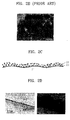
- the catalyst layer according to the present invention has a structure as illustrated in FIGS. 2C through 2F.
- FIG. 2C is a schematic view of a catalyst layer according to the present invention.
- FIGS. 2D through 2F are transmission electron microscope (TEM) photos ( ⁇ 500,000) of the catalyst layers according to the present invention.
- TEM transmission electron microscope
- nano-sized carbon and metal catalyst particles are uniformly dispersed as a catalyst layer over a proton exchange membrane.
- the catalyst layer is dense and can formed as a thin film. Use of the catalyst layer including uniformly dispersed catalyst and carbon particles improves utilization efficiency of the catalyst, compared to the conventional catalyst layer illustrated in FIGS. 2A and 2B.
- the membrane electrode assembly may be included in a PEMFC as shown as Figure 5.
- the difference to the prior art arrangement is that the catalyst layers 21 are formed as will be described further below.
- a proton exchange polymer membrane as a base is pre-treated to allow easy coating of metal catalyst and carbon in subsequent processes. This pre-treatment also ensures reactions efficiency after the coating of the catalyst and carbon particles is completed.
- the pre-treatment involves removing water from the surface of a proton exchange polymer membrane, which has undergone a cleaning process, in a reaction chamber in a vacuum state, wherein the reaction chamber will be used for the coating of catalytic metal and carbon.
- Suitable catalytic metal sources include pure platinum (Pt), an alloy and a mixture of Pt and at least one metal selected from the group consisting of gold (Au), palladium (Pd), rhodium (Rh), iridium (Ir), ruthenium (Rh), tin (Sn), and molybdenum (Mo). It is more preferable that Pt is used as a catalytic metal source for proton exchange membrane fuel cells (PEMFCs), and a Pt/Ru alloy is used for direct methanol fuel cells (DMFCs), in terms of catalyst utilization efficiency. It is also preferable that the catalytic metal has a particle size of 2-10 nm for catalyst utilization efficiency.
- Any known sputtering method may be applied to coat the proton exchange polymer membrane with the catalytic metal.
- a magnetron direct current (DC) sputtering method is more preferred.
- DC direct current
- this sputtering method as metal atoms fall down from a bulk target by attack of accelerated inert gas, plasma is uniformly formed by a magnetron, and the metal in a plasma state is coated on the proton exchange polymer membrane. This coating allows uniform dispersion of nano-sized catalytic metal.
- the sputtering conditions may be varied according to the particle size of catalytic metal, and the degree of dispersion of catalytic metal.
- Chamber is evacuated to a vacuum level at 10 -6 Pa or less.
- an inert gas is used as a reaction gas for the sputtering.
- Ar argon
- He a mixture of Ar and helium
- Ar is directly involved in sputtering, and He acts to adjust the porosity of the resulting metal coated layer by hitting the metal particles in a plasma state to take a portion of their kinetic energy. If the metal coated layer is highly dense due to its low porosity, fuel transfer is not easy.
- a gas pressure is preferably adjusted in the range of 10-1,000 Pa, and a sputter gun power is preferably adjusted in the range of 100-400W.
- This gas pressure level is higher than for a general thin film formation process performed at a gas pressure of 0.1-0.01 Pa. If the gas pressure for sputtering is less than 10 Pa, the resulting catalyst layer is so dense that gaseous or liquid fuel permeability becomes low. If the gas pressure for sputtering exceeds 1,000 Pa, uniform plasma formation is not ensured.
- the sputter gun power is less than 100W, the resulting catalyst layer has a smaller particle size than desired. If the sputter gun power is greater than 400W, uniform plasma formation is not ensured.
- the sputtering described above is repeated for the other side to coat nano-sized catalytic metal thereon.
- the amount of catalytic metal loading may be varied according to sputtering time and sputtering power.
- the particle size of catalytic metals is determined depending on the reaction gas pressure and sputtering power.
- the sputtering is carried out a few times with a predetermined time gap, rather than as a one-step continuous process.
- nano-sized carbon particles are coated on one side of the catalytic metal coated proton exchange polymer membrane by sputtering, or by a cathode arc discharge method.
- a carbon source at least one of graphite and carbon rod is used.
- a sputtering method is selected to coat carbon particles, the same sputtering conditions as in the catalytic metal sputtering are applied for the carbon sputtering. If an arc discharge method is selected, the power level and discharging time may be adjusted to form a carbon coated layer with a desired thickness and nano-sized particles.
- the gas pressure is adjusted in the range of 10-1,000 Pa, and a discharge current is adjusted to 100A or less. If the gas pressure is lower than 10 Pa, the resulting catalyst layer is so dense that gaseous or liquid fuel permeability becomes low. If the gas pressure for sputtering exceeds 1,000 Pa, uniform plasma formation is not ensured. If the discharge current exceeds 100A, uniformity and size of the carbon particles cannot be accurately controlled.
- the same process is performed upon the other side of the proton exchange polymer membrane to coat nano-sized carbon particles thereon as a nanophase catalyst layer.
- the size of carbon particles is in the range of 2-5 nm. More preferably, the shape and size of carbon particles are similar to those of the coated catalytic metal in terms of catalyst utilization efficiency.
- the resulting catalyst layer has a thickness of 10-100 nm, If the thickness of the catalyst layer is greater than 100 nm, it is difficult to form the effective interface with the proton membrane.
- the amount of catalyst loading per electrode area is preferable in the range of 0.01-0,2 mg/cm 2 for PEMFCs, and in the range of 0.1-2 mg/cm 2 for DMFCs. If the amount of catalyst loading is below these ranges, the catalytic activity is poor. If the amount of catalyst loading exceeds these ranges, utilization efficiency of the catalyst becomes lower.
- the amount of the catalytic metal coated by the method described previously is preferably in the range of 20-85% by weight, more preferably, 25-80% by weight, based on the total amount of catalytic metal and carbon particles. If the amount of the catalytic metal is below this range, utilization efficiency of the catalyst decreases. If the amount of the catalytic metal exceeds this range, fuel permeability becomes poor.
- an alloy or mosaic target having an intended catalyst composition may be used as a catalytic metal source.
- a plurality of sputter guns each of which hits 2-3 targets may be used.
- the nanophase catalyst layer is formed with nano-sized catalytic metal and carbon particles, as previously described, the catalytic metals and carbon particles penetrate deeply into the proton exchange polymer membrane through its cavities, so that efficiency of oxidation and reduction reactions occurring near the surfaces of the proton exchange polymer membrane much increases compared with the conventional catalyst layer illustrated in FIG. 2A.
- a catalytic layer can be formed on both side of the proton exchange membrane in a thin film form.
- the catalyst layer adjacent to the anode is formed as a thin film, cross-over of methanol can be effectively suppressed.
- the catalyst layer is formed by two-stages coating: coating of catalytic metal, and coating of carbon particles, catalytic metal and carbon particles may be simultaneously coated on the proton exchange membrane by sputtering. It is preferable that the catalytic metal is coated by magnetron sputtering, and the carbon particles are coated by radio frequency (RF) sputtering.
- RF radio frequency
- Electrodes are placed on each side of the proton exchange membrane coated with nano-sized catalytic metal and carbon particles, and hot pressed to form a complete membrane-electrode assembly according to the present invention.
- the pressing temperature is determined such that the proton exchange membrane is soften in that temperature range, for example, to 125°C for a Nafion (a registered trademark of E.I. duPong Nemours).
- the pressure level is about 200 kgf/cm 2 .
- As the electrodes a conductive carbon cloth or carbon paper may be used.
- a bipolar plate is attached to both sides of the membrane-electrode assembly, so that a completed fuel cell is obtained.
- the bipolar plate has cavities through which fuel is supplied inside the cell, and also serves as a current collector.
- Nafion 115 manufactured by duPont as a proton exchange polymer membrane was pre-treated as follows.
- a stainless steel made support frame was manufactured for easy handling in a vacuum chamber, and a predetermined active region (25 cm 2 ) of the proton exchange polymer membrane was exposed through the support frame.
- the corners of the proton exchange polymer membrane were fixed to the support frame, and left in a vacuum for 10 minutes to remove water. The degree of vacuum was controlled at 10 -6 Pa.
- One side of the pre-treated proton exchange polymer membrane was coated with Pt by magnetron sputtering.
- the magnetron sputtering was carried out for 400 seconds using a gas mixture of Ar and He in a 1:1 ratio as a reaction gas at a pressure of 100 Pa with a sputter gun power of 300 W.
- two sputterings were carried out each for 200 seconds.
- the other side of the proton exchange polymer membrane is coated with Pt by the same sputtering.
- the coated Pt catalyst had a particle size of about 3 nm.
- the Pt-coated proton exchange polymer membrane which was fixed to the stainless steel made support frame was transferred to an arc chamber.
- a graphite bar is used as a carbon source, and a predetermined voltage that causes a discharge current of 40A is applied to the electrode to coat one side of the proton exchange polymer membrane with carbon.
- the other side of the catalyzed proton exchange polymer membrane was coated with carbon by the same discharging, so that the both sides of the proton exchange polymer membranes were coated with catalyst and carbon.
- the pressure of the arc chamber was controlled about 10 Pa. Three arc dischargings were carried upon each side of the proton exchange polymer membrane each for 10 seconds.
- the amount of coated Pt was 0.06 mg/cm 2 and the amount of carbon was 0.6 mg/cm 2 .
- the particle size of Pt and carbon particles was 3 nm.
- the amount of Pt was equivalent to 25% by weight based on the total weight of the Pt and carbon particles.
- a carbon paper (Toray Carbon Paper, E-Tek Co.), which was water-proof treated with a 20:80 tetrafluoroethylene and hexafluoropropylene copolymer, was used as a backing layer.
- the carbon paper was bonded to the proton exchange polymer to obtain a membrane-electrode assembly (MEA). This bonding process was carried out using a hot press at 125°C with a load of about 200 kgf/cm 2 for 3 minutes.
- a PEMFC was manufactured with the MEA.
- a proton exchange polymer membrane (Nafion 115) adjacent to the anode was coated simultaneously with a Pt/Ru alloy by DC sputtering and with carbon by RF sputtering, and then other side was coated with Pt and carbon by the same methods, to form catalyst layers on the proton exchange polymer membrane.
- the gas pressure as a total pressure of Ar and He was 100 Pa.
- the DC sputtering was performed under the same conditions as in Example 1, and the RF sputtering was performed with a power of 300 W.
- a MEA and a DMFC were manufactured in a similar manner to that of Example 1.
- the amount of coated Pt/Pu alloy and Pt was 1.5 mg/cm 2
- the amount of coated carbon was 0.375 mg/cm 2
- the particle size of the catalytic metals and the carbon particles was in the range of 5-10 nm.
- the amount of the catalytic metals was equivalent to 80% by weight based on the total weight of the catalytic metal and carbon particles.
- a catalyst layer was formed by a spray method with Pt-doped carbon support (20% Pt/C, E-Tek Co.) formed by electrochemical reduction.
- a MEA and a PEMFC were manufactured in the same manner as in Example 1.
- the amount of coated Pt was 0.2 mg/cm 2 , which was 100 times more than the PEMFC of Example 1.
- the amount of carbon particles was 0.8 mg/cm 2 .
- the amount of the Pt was equivalent to 20% by weight based on the total weight of the Pt and carbon particles.
- the particle size of the coated catalytic metal was about 5 nm, and the particle size of the carbon particles was about 100 nm.
- a MEA and PEMFC were manufactured in the same manner as in Comparative Example 1, except that the amount of Pt coated per electrode area was 0.02 mg/cm 2 .
- a catalyst layer was formed by a spray method with a Pt/Ru-doped carbon support (60% Pt-Ru/C, E-Tek Co.) formed by electrochemical reduction, and a Pt-doped carbon support (20% Pt/C, E-Tek Co.).
- a MEA and a DMFC were manufactured in the same manner as in Example 2.
- the amount of carbon particles was 3.2 mg/cm 2 .
- the amount of the catalytic metals was equivalent to 60% by weight based on the total weight of the catalytic metals and carbon particles.
- the particle size of the coated catalytic metals was about 5 nm, and the particle size of the carbon particles was about 100 nm.
- a MEA and DMFC were manufactured in the same manner as in Comparative Example 3, except that the amount of Pt/Ru and the amount of Pt coated per electrode area were 1.5 mg/cm 2 .
- the PEMFCs manufactured in Example 1, and Comparative Examples 1 and 2 were operated using humidified oxygen and hydrogen gases (a 1:1 gas pressure ratio), and the polarization characteristics and power densities of the PEMFCs were evaluated. As the results, the structure of the catalyst layer of Example 1 is improved, as shown in the TEM photo of FIG. 2D. The polarization characteristic and the power density are improved for the PEMFC of Example 1, as shown in FIG. 3, compared with the PEMFCs of Comparative Examples 1 and 2.
- the DMFCs manufactured in Example 2, and Comparative Examples 3 and 4 were operated using a 2-M methanol solution and air, and the polarization characteristics and power densities of the DMFCs were evaluated. As the results, the structure of the catalyst layer of Example 2 is improved, as shown in the TEM photos of FIG. 2E and 2F. The polarization characteristic and the power density are excellent for the DMFC of Example 2, as shown in FIG. 4, compared with the DMFCs of Comparative Examples 3 and 4. In particular, unlike the DMFCs of Comparative Examples 3 and 4, the catalyst layer of the DMFC of Example 2 which is adjacent to the anode is formed as a thin film, so that cross-over of methanol can be suppressed.
Landscapes
- Life Sciences & Earth Sciences (AREA)
- Engineering & Computer Science (AREA)
- Manufacturing & Machinery (AREA)
- Sustainable Development (AREA)
- Sustainable Energy (AREA)
- Chemical & Material Sciences (AREA)
- Chemical Kinetics & Catalysis (AREA)
- Electrochemistry (AREA)
- General Chemical & Material Sciences (AREA)
- Inert Electrodes (AREA)
- Fuel Cell (AREA)
- Physical Vapour Deposition (AREA)
Abstract
Description
- The present invention relates to a method for fabricating a membrane-electrode assembly and fuel cells adopting a membrane-electrode assembly formed by the method, and more particularly, to a method for fabricating a membrane-electrode assembly employing a nanophase catalyzed membrane, in which the size of carbon particles serving as a support catalyst is controlled, and fuel cells with an improved power density, which use a membrane-electrode assembly containing the catalyzed membrane formed by the method.
- Proton exchange membrane fuel cells (PEMFCs) emerging as a future generation clean energy source alternative to fossil energy have a high power density and a high energy conversion efficiency. In addition, the PEMFC is workable at room temperature and is easy to seal and miniaturize, so that it can be extensively applied to the field of portable electronic devices.
- The PEMFC is a power generator for producing direct current through electrochemical reaction of hydrogen and oxygen. The basic structure of such a cell is shown in FIG. 1. Referring to FIG. 1, the PEMFC has a
proton exchange membrane 11 interposed between the anode and the cathode to which reaction gases are supplied. Theproton exchange membrane 11 is formed of a solid polymer electrolyte (SPE) with a thickness of 50-200 µm. The anode consists of ananode backing layer 14 and acatalyst layer 12 on theanode backing layer 14. The cathode consists of acathode backing layer 15 and a catalyst layer on thecathode backing layer 15. The anode and cathode backinglayers layers proton exchange membrane 11. In FIG. 1,reference numeral 16 denotes a bipolar plate serving as a current collector and having flow pattern for gas supply. - As reaction gases are supplied to a PEMFC having such a structure described above, hydrogen molecules are decomposed into protons and electrons by oxidation reaction in the anode. The produced protons reach the cathode through the
proton exchange membrane 11. Meanwhile, in the cathode oxygen molecules take electrons from the anode and are reduced to oxygen ions by reduction. The produced oxygen ions react with hydrogen ions from the anode and produce water. - On the other hand, direct methanol fuel cells (DMFCs) have the same structure as the PEMFC described previously, but using liquid methanol, instead of hydrogen, as a fuel source. As methanol is supplied to the anode, an oxidation reaction occurs in the presence of a catalyst, so that protons, electrons and carbon dioxide are generated. Although energy efficiency of the DMFC is lower than the PEMFC, use of a liquid fuel in the DMFC makes its application to potable electronic devices easier.
- In the previously described fuel cells, as shown in FIG. 2A, a
catalyst layer 21 includescarbon particles 22 loaded withcatalytic metal particle 23, and a binder (not shown). Thecarbon particles 22 as a reaction base for the incoming reaction gases increase the chance of occurrence of the gases reactions. Thecatalytic metal particle 23 initiates an oxidation/reduction of fuel sources, such as hydrogen, methanol or oxygen. The binder contributes to strengthening the binding force between the catalyst layer and the proton exchange membrane to prevent delamination of the catalyst layer from electrodes even if the cell is used for a longer period of time. - Carbon particles are loaded with catalytic metal particles typically by a reduction method. According to this reduction method, a compound having a catalytic metal as its cation is reduced such that only the catalytic metal appears on the surface of a carrier such as carbon particles. As a result, the surface of carbon particles is coated with catalytic metals. A method for forming a catalytic layer using such catalytic metal loaded carbon particles will be described below.
- First, platinum-on-carbon (Pt/C) is prepared by coating 0.1-µm carbon particles with 2∼5-nm ultrafine catalytic metal particles, for example, platinum particles, and polytetrafluoroethylene is added as a binder. The resulting composition is deposited in a film form, impregnated with an ionomer solution, and dried, thereby resulting in a complete catalytic layer.
- However, this method is disadvantageous in that the entire volume of carbon particles cannot be fully utilized because carbon particles are tens to hundreds times larger than catalytic metal particles. Furthermore, another drawback lies in that a contact area between the proton exchange membrane and the catalytic layers, where catalytic reactions take place, is so small. Because the reactions, such as diffusion of reaction gases, or collection of current, take place in the catalyst-and-carbon particles contact surface, such a catalyst structure in which a relatively large carbon particle is loaded with a large number of catalytic particles is considered as being inefficient.
- To solve this problem, a method for forming a catalyst layer directly on a proton conductive membrane by a decal process (US 5,234,777), and a method for uniformly dispersing a catalytic metal over the surface of electrodes (Electrochemical Acta., Vol. 42, No. 10, pp. 1587-1593) have been suggested.
- To the former, a catalytic layer composition is coated on a support, and then peeled off to obtain a thin catalyst film. The catalyst film is pressed into the surface of a proton exchange membrane to form a complete catalytic layer. However, this method has the following disadvantages. Although the formation of the catalytic layer is effective in increasing the contact area between the catalytic layer and the proton exchange membrane, it is difficult to fully disperse catalyst particles over the surface of the proton exchange membrane because carbon particles serving as a support for the catalyst have a size of a few micrometers. This is evidenced from FIGS. 2A and 2B. To produce an electrode with a higher power density than a predetermined level, the amount of reaction gases for reactions as well as the amount of catalyst must be increased. The increased amount of reaction gases lowers utilization efficiency of the catalyst, and undesirably increases the weight, volume and price of a completed cell. The catalytic layer is bonded to the proton exchange membrane by high-temperature and high-pressure pressing, so that the proton exchange membrane degrades during this hot pressing process.
- On the other hand, according to the conventional method for dispersing catalyst metals over the surface of electrodes by sputtering, catalyst utilization efficiency is low because the catalytic metal particles penetrate into porous electrodes. Because the catalytic metal particles are coated on the surface of the carbon particles having a size of a few micrometers, bonding between the catalyst layer and the proton exchange membrane, which allows electrochemical reactions to occur at the contact area, can not be smoothly achieved, so that utilization efficiency of the catalyst becomes low.
- Accordingly, there is a need for an improved method for fabricating a membrane-electrode assembly with an improved structure.
- There is also a need for fuel cells with improved power densities.
- According to an aspect of the first object of the present invention, there is provided a method for fabricating a membrane-electrode assembly, the method comprising; coating nano-sized catalytic metal particles on a proton exchange polymer membrane by sputtering a catalytic metal source; coating nano-sized carbon particles on the proton exchange polymer membrane by arc discharging or by sputtering a carbon source to form a nanophase catalyst layer; and bonding electrodes to the proton exchange polymer membrane having the nanophase catalyst layer.
- According to another aspect of the first object of the present invention, there is provided a method for fabricating a membrane-electrode assembly, the method comprising; coating nano-sized catalytic metal and carbon particles on a proton exchange polymer membrane by simultaneously sputtering a catalytic metal source and a carbon source to form a nanophase catalyst layer; and bonding electrodes to the proton exchange polymer membrane having the nanophase catalyst layer.
- In the membrane-electrode assembly fabrication methods, the catalytic metal source may comprise a pure platinum (Pt), and an alloy and a mixture of Pt and at least one metal selected from the group consisting of gold (Au), palladium (Pd), rhodium (Rh), iridium (Ir), ruthenium (Rh), tin (Sn), and molybdenum (Mo). The carbon source may be at least one of graphite and carbon rod. It is preferable that the catalyst layer has a thickness of 10-100 nm, and the coated catalytic metal and carbon particles have a particle size of 2-10 nm.
- The invention may control the size of the carbon particles serving as a support catalyst so that fuel can be efficiently supplied with a high utilization efficiency of the catalyst.
- The invention also relates to fuel cells adopting a membrane-electrode assembly formed by the methods described above.
- The invention also relates to a membrane-electrode assembly comprising: a proton exchange polymer membrane (11); a catalyst layer (21) having catalytic metal particles (23) and carbon particles (22); and electrodes (14, 15) attached to the proton exchange polymer membrane (11) and catalyst layer (21) wherein the catalyst layer (21) has a thickness of 10-100nm and the coated catalytic metal particles (23) and the carbon particles (22) have a particle size of 2-10nm.
- The above objects and advantages of the present invention will become more apparent by describing in detail preferred embodiments thereof with reference to the attached drawings in which:
- FIG. 1 illustrates the structure of a proton exchange membrane fuel cell (PEMFC);
- FIG. 2A illustrates the structure of a conventional catalyst layer;
- FIG. 2B is a transmission electron microscope (TEM) photo (× 500,000) of the conventional catalyst layer;
- FIG. 2C is a schematic view of a catalyst layer according to a preferred embodiment of the present invention;
- FIGS. 2D, 2E and 2F are TEM photos (× 500,000) of the catalyst layer according to the present invention;
- FIG. 3 is a graph illustrating cell potential variations with respect to current density in the PEMFCs of Example 1 and Comparative Examples 1-2; and
- FIG. 4 is a graph illustrating cell potential variations with respect to current density in the direct methanol fuel cells (DMFCs) of Example 2 and Comparative Examples 3-4.
-
- The terms "membrane-electrode assembly" used through this specification are defined as an assembled structure including a proton exchange membrane interposed between an anode and cathode.
- In a method for fabricating a membrane-electrode assembly according to the present invention, the proton exchange membrane employing a catalyst layer is prepared by coating the proton exchange membrane with a catalytic metal, and then with carbon. Alternatively, a catalytic metal and carbon may be simultaneously coated on a proton exchange membrane to form the proton exchange membrane. The particles of the coated catalytic metal and carbon are nano-sized and vary according to the conditions of sputtering and arc discharge applied to the coatings.
- The catalyst layer according to the present invention has a structure as illustrated in FIGS. 2C through 2F. FIG. 2C is a schematic view of a catalyst layer according to the present invention. FIGS. 2D through 2F are transmission electron microscope (TEM) photos (× 500,000) of the catalyst layers according to the present invention. Referring to FIGS. 2C through 2F, nano-sized carbon and metal catalyst particles are uniformly dispersed as a catalyst layer over a proton exchange membrane. The catalyst layer is dense and can formed as a thin film. Use of the catalyst layer including uniformly dispersed catalyst and carbon particles improves utilization efficiency of the catalyst, compared to the conventional catalyst layer illustrated in FIGS. 2A and 2B.
- The membrane electrode assembly may be included in a PEMFC as shown as Figure 5. The difference to the prior art arrangement is that the catalyst layers 21 are formed as will be described further below.
- A method for forming a catalyst layer for a membrane-electrode assembly according to the present invention will be described in greater detail. First, a proton exchange polymer membrane as a base is pre-treated to allow easy coating of metal catalyst and carbon in subsequent processes. This pre-treatment also ensures reactions efficiency after the coating of the catalyst and carbon particles is completed. The pre-treatment involves removing water from the surface of a proton exchange polymer membrane, which has undergone a cleaning process, in a reaction chamber in a vacuum state, wherein the reaction chamber will be used for the coating of catalytic metal and carbon. For the pre-treatment by vacuum drying, or for the coating of catalytic metal and carbon particles, which will be described later, it is preferable to fix the corners of the proton exchange polymer layer to a support frame having a predetermined size for levelling.
- Once the pre-treatment is completed, nano-sized metal catalyst particles are coated over one side of the proton exchange polymer membrane by sputtering. Suitable catalytic metal sources include pure platinum (Pt), an alloy and a mixture of Pt and at least one metal selected from the group consisting of gold (Au), palladium (Pd), rhodium (Rh), iridium (Ir), ruthenium (Rh), tin (Sn), and molybdenum (Mo). It is more preferable that Pt is used as a catalytic metal source for proton exchange membrane fuel cells (PEMFCs), and a Pt/Ru alloy is used for direct methanol fuel cells (DMFCs), in terms of catalyst utilization efficiency. It is also preferable that the catalytic metal has a particle size of 2-10 nm for catalyst utilization efficiency.
- Any known sputtering method may be applied to coat the proton exchange polymer membrane with the catalytic metal. A magnetron direct current (DC) sputtering method is more preferred. According to this sputtering method, as metal atoms fall down from a bulk target by attack of accelerated inert gas, plasma is uniformly formed by a magnetron, and the metal in a plasma state is coated on the proton exchange polymer membrane. This coating allows uniform dispersion of nano-sized catalytic metal. Here, the sputtering conditions may be varied according to the particle size of catalytic metal, and the degree of dispersion of catalytic metal.
- Chamber is evacuated to a vacuum level at 10-6 Pa or less. As a reaction gas for the sputtering, an inert gas is used. Preferably, argon (Ar) or a mixture of Ar and helium (He) is used to keep a vacuum level at 10-6 Pa or less. Here, Ar is directly involved in sputtering, and He acts to adjust the porosity of the resulting metal coated layer by hitting the metal particles in a plasma state to take a portion of their kinetic energy. If the metal coated layer is highly dense due to its low porosity, fuel transfer is not easy.
- During the sputtering, a gas pressure is preferably adjusted in the range of 10-1,000 Pa, and a sputter gun power is preferably adjusted in the range of 100-400W. This gas pressure level is higher than for a general thin film formation process performed at a gas pressure of 0.1-0.01 Pa. If the gas pressure for sputtering is less than 10 Pa, the resulting catalyst layer is so dense that gaseous or liquid fuel permeability becomes low. If the gas pressure for sputtering exceeds 1,000 Pa, uniform plasma formation is not ensured.
- If the sputter gun power is less than 100W, the resulting catalyst layer has a smaller particle size than desired. If the sputter gun power is greater than 400W, uniform plasma formation is not ensured.
- Once the catalyst layer is deposited on one side of the proton exchange polymer membrane, the sputtering described above is repeated for the other side to coat nano-sized catalytic metal thereon. The amount of catalytic metal loading may be varied according to sputtering time and sputtering power. The particle size of catalytic metals is determined depending on the reaction gas pressure and sputtering power.
- To prevent heat transfer from the target to the proton exchange polymer membrane, it is preferable that the sputtering is carried out a few times with a predetermined time gap, rather than as a one-step continuous process.
- After the catalytic metal sputtering is completed, nano-sized carbon particles are coated on one side of the catalytic metal coated proton exchange polymer membrane by sputtering, or by a cathode arc discharge method. As a carbon source, at least one of graphite and carbon rod is used.
- If a sputtering method is selected to coat carbon particles, the same sputtering conditions as in the catalytic metal sputtering are applied for the carbon sputtering. If an arc discharge method is selected, the power level and discharging time may be adjusted to form a carbon coated layer with a desired thickness and nano-sized particles.
- When a carbon source is deposited by arc discharging, the gas pressure is adjusted in the range of 10-1,000 Pa, and a discharge current is adjusted to 100A or less. If the gas pressure is lower than 10 Pa, the resulting catalyst layer is so dense that gaseous or liquid fuel permeability becomes low. If the gas pressure for sputtering exceeds 1,000 Pa, uniform plasma formation is not ensured. If the discharge current exceeds 100A, uniformity and size of the carbon particles cannot be accurately controlled.
- The same process is performed upon the other side of the proton exchange polymer membrane to coat nano-sized carbon particles thereon as a nanophase catalyst layer. It is preferable that the size of carbon particles is in the range of 2-5 nm. More preferably, the shape and size of carbon particles are similar to those of the coated catalytic metal in terms of catalyst utilization efficiency.
- It is preferable that the resulting catalyst layer has a thickness of 10-100 nm, If the thickness of the catalyst layer is greater than 100 nm, it is difficult to form the effective interface with the proton membrane.
- The amount of catalyst loading per electrode area is preferable in the range of 0.01-0,2 mg/cm2 for PEMFCs, and in the range of 0.1-2 mg/cm2 for DMFCs. If the amount of catalyst loading is below these ranges, the catalytic activity is poor. If the amount of catalyst loading exceeds these ranges, utilization efficiency of the catalyst becomes lower.
- The amount of the catalytic metal coated by the method described previously is preferably in the range of 20-85% by weight, more preferably, 25-80% by weight, based on the total amount of catalytic metal and carbon particles. If the amount of the catalytic metal is below this range, utilization efficiency of the catalyst decreases. If the amount of the catalytic metal exceeds this range, fuel permeability becomes poor.
- When a binary or ternary catalytic metal is applied, an alloy or mosaic target having an intended catalyst composition may used as a catalytic metal source. Alternatively, a plurality of sputter guns each of which hits 2-3 targets may be used.
- When the nanophase catalyst layer is formed with nano-sized catalytic metal and carbon particles, as previously described, the catalytic metals and carbon particles penetrate deeply into the proton exchange polymer membrane through its cavities, so that efficiency of oxidation and reduction reactions occurring near the surfaces of the proton exchange polymer membrane much increases compared with the conventional catalyst layer illustrated in FIG. 2A. In addition, a catalytic layer can be formed on both side of the proton exchange membrane in a thin film form. In particular, for a DMFC with a proton exchange polymer membrane, the catalyst layer adjacent to the anode is formed as a thin film, cross-over of methanol can be effectively suppressed.
- Although in the previous description the catalyst layer is formed by two-stages coating: coating of catalytic metal, and coating of carbon particles, catalytic metal and carbon particles may be simultaneously coated on the proton exchange membrane by sputtering. It is preferable that the catalytic metal is coated by magnetron sputtering, and the carbon particles are coated by radio frequency (RF) sputtering.
- A method for fabricating a membrane-electrode assembly according to the present invention will be described below. Electrodes are placed on each side of the proton exchange membrane coated with nano-sized catalytic metal and carbon particles, and hot pressed to form a complete membrane-electrode assembly according to the present invention. The pressing temperature is determined such that the proton exchange membrane is soften in that temperature range, for example, to 125°C for a Nafion (a registered trademark of E.I. duPong Nemours). The pressure level is about 200 kgf/cm2. As the electrodes, a conductive carbon cloth or carbon paper may be used.
- Following this, a bipolar plate is attached to both sides of the membrane-electrode assembly, so that a completed fuel cell is obtained. The bipolar plate has cavities through which fuel is supplied inside the cell, and also serves as a current collector.
- The present invention will be described in greater detail by means of the following examples. The following examples are for illustrative purposes and are not intended to limit the scope of the invention.
- Nafion 115 (manufactured by duPont) as a proton exchange polymer membrane was pre-treated as follows. A stainless steel made support frame was manufactured for easy handling in a vacuum chamber, and a predetermined active region (25 cm2) of the proton exchange polymer membrane was exposed through the support frame. The corners of the proton exchange polymer membrane were fixed to the support frame, and left in a vacuum for 10 minutes to remove water. The degree of vacuum was controlled at 10-6 Pa.
- One side of the pre-treated proton exchange polymer membrane was coated with Pt by magnetron sputtering. The magnetron sputtering was carried out for 400 seconds using a gas mixture of Ar and He in a 1:1 ratio as a reaction gas at a pressure of 100 Pa with a sputter gun power of 300 W. To avoid heat transfer from the target to the proton exchange polymer membrane arising from a long sputtering period, two sputterings were carried out each for 200 seconds.
- Once the sputtering was completed, the other side of the proton exchange polymer membrane is coated with Pt by the same sputtering. The coated Pt catalyst had a particle size of about 3 nm.
- The Pt-coated proton exchange polymer membrane which was fixed to the stainless steel made support frame was transferred to an arc chamber. A graphite bar is used as a carbon source, and a predetermined voltage that causes a discharge current of 40A is applied to the electrode to coat one side of the proton exchange polymer membrane with carbon. The other side of the catalyzed proton exchange polymer membrane was coated with carbon by the same discharging, so that the both sides of the proton exchange polymer membranes were coated with catalyst and carbon. The pressure of the arc chamber was controlled about 10 Pa. Three arc dischargings were carried upon each side of the proton exchange polymer membrane each for 10 seconds. The amount of coated Pt was 0.06 mg/cm2 and the amount of carbon was 0.6 mg/cm2. The particle size of Pt and carbon particles was 3 nm. The amount of Pt was equivalent to 25% by weight based on the total weight of the Pt and carbon particles.
- A carbon paper (Toray Carbon Paper, E-Tek Co.), which was water-proof treated with a 20:80 tetrafluoroethylene and hexafluoropropylene copolymer, was used as a backing layer. The carbon paper was bonded to the proton exchange polymer to obtain a membrane-electrode assembly (MEA). This bonding process was carried out using a hot press at 125°C with a load of about 200 kgf/cm2 for 3 minutes. A PEMFC was manufactured with the MEA.
- One side of a proton exchange polymer membrane (Nafion 115) adjacent to the anode was coated simultaneously with a Pt/Ru alloy by DC sputtering and with carbon by RF sputtering, and then other side was coated with Pt and carbon by the same methods, to form catalyst layers on the proton exchange polymer membrane. The gas pressure as a total pressure of Ar and He was 100 Pa. The DC sputtering was performed under the same conditions as in Example 1, and the RF sputtering was performed with a power of 300 W. With the catalyzed proton exchange polymer membrane a MEA and a DMFC were manufactured in a similar manner to that of Example 1. The amount of coated Pt/Pu alloy and Pt was 1.5 mg/cm2, and the amount of coated carbon was 0.375 mg/cm2. The particle size of the catalytic metals and the carbon particles was in the range of 5-10 nm. The amount of the catalytic metals was equivalent to 80% by weight based on the total weight of the catalytic metal and carbon particles.
- A catalyst layer was formed by a spray method with Pt-doped carbon support (20% Pt/C, E-Tek Co.) formed by electrochemical reduction. A MEA and a PEMFC were manufactured in the same manner as in Example 1. The amount of coated Pt was 0.2 mg/cm2, which was 100 times more than the PEMFC of Example 1. The amount of carbon particles was 0.8 mg/cm2. The amount of the Pt was equivalent to 20% by weight based on the total weight of the Pt and carbon particles. The particle size of the coated catalytic metal was about 5 nm, and the particle size of the carbon particles was about 100 nm.
- A MEA and PEMFC were manufactured in the same manner as in Comparative Example 1, except that the amount of Pt coated per electrode area was 0.02 mg/cm2.
- A catalyst layer was formed by a spray method with a Pt/Ru-doped carbon support (60% Pt-Ru/C, E-Tek Co.) formed by electrochemical reduction, and a Pt-doped carbon support (20% Pt/C, E-Tek Co.). A MEA and a DMFC were manufactured in the same manner as in Example 2. The amount of Pt/Ru (Pt:Ru=1:1) coated and the amount of Cu coated were 8 mg/cm2, which were 5.3 times more than the DMFC of Example 2. The amount of carbon particles was 3.2 mg/cm2. The amount of the catalytic metals was equivalent to 60% by weight based on the total weight of the catalytic metals and carbon particles. The particle size of the coated catalytic metals was about 5 nm, and the particle size of the carbon particles was about 100 nm.
- A MEA and DMFC were manufactured in the same manner as in Comparative Example 3, except that the amount of Pt/Ru and the amount of Pt coated per electrode area were 1.5 mg/cm2.
- The PEMFCs manufactured in Example 1, and Comparative Examples 1 and 2 were operated using humidified oxygen and hydrogen gases (a 1:1 gas pressure ratio), and the polarization characteristics and power densities of the PEMFCs were evaluated. As the results, the structure of the catalyst layer of Example 1 is improved, as shown in the TEM photo of FIG. 2D. The polarization characteristic and the power density are improved for the PEMFC of Example 1, as shown in FIG. 3, compared with the PEMFCs of Comparative Examples 1 and 2.
- The DMFCs manufactured in Example 2, and Comparative Examples 3 and 4 were operated using a 2-M methanol solution and air, and the polarization characteristics and power densities of the DMFCs were evaluated. As the results, the structure of the catalyst layer of Example 2 is improved, as shown in the TEM photos of FIG. 2E and 2F. The polarization characteristic and the power density are excellent for the DMFC of Example 2, as shown in FIG. 4, compared with the DMFCs of Comparative Examples 3 and 4. In particular, unlike the DMFCs of Comparative Examples 3 and 4, the catalyst layer of the DMFC of Example 2 which is adjacent to the anode is formed as a thin film, so that cross-over of methanol can be suppressed.
- As previously described, use of nano-sized catalytic metal and carbon particles enlarges the contact area between the catalyst layer and proton exchange polymer membrane. In addition, ultrafine catalytic metal particles are easy to penetrate into the proton exchange polymer membrane through small cavities formed on the surface. This structure of the catalyst layer allows oxidation and reduction reactions to occur at the surface of the proton exchange polymer membrane with a high efficiency. Direct coating such catalytic metal and carbon particles on the proton exchange polymer membrane reduces the amount of catalyst required, and improves catalyst utilization efficiency with improved fuel gas permeability. Furthermore, the catalyst layer adjacent to the anode is formed in a thin film form, so that cross-over of methanol can be effectively suppressed for a DMFC using the liquid fuel.
- While this invention has been particularly shown and described with reference to preferred embodiments thereof, it will be understood by those skilled in the art that various changes in form and details may be made therein without departing from the spirit and scope of the invention as defined by the appended claims.
Claims (16)
- A method for fabricating a membrane-electrode assembly, the method comprising;coating nano-sized catalytic metal particles on a proton exchange polymer membrane by sputtering a catalytic metal source;coating nano-sized carbon particles on the proton exchange polymer membrane by arc discharging or by sputtering a carbon source to form a nanophase catalyst layer; andbonding electrodes to the proton exchange polymer membrane having the nanophase catalyst layer.
- The method of claim 1, wherein the catalytic metal source comprises a pure platinum (Pt), and an alloy and an mixture of Pt and at least one metal selected from the group consisting of gold (Au), palladium (Pd), rhodium (Rh), iridium (Ir), ruthenium (Rh), tin (Sn), and molybdenum (Mo); and the carbon source is at least one selected from graphite and carbon rod.
- The method of claim 1, wherein the catalyst layer has a thickness of 10-100 nm, and the coated catalytic metal and carbon particles have a particle size of 2-10 nm.
- The method of claim 1, wherein the amount of the catalytic metal loading per electrode area is in the range of 0.01-0.2 mg/cm2 for a proton exchange membrane fuel cell, and is in the range of 0.1-2 mg/cm2 for a direct methanol fuel cell.
- The method of claim 1, wherein the amount of the catalytic metal coated is in the range of 20-85% by weight based on the total weight of the catalytic metal and the carton particles.
- The method of claim 1, wherein sputtering the catalytic metal source or the carbon source is carried out at a gas pressure of 10-1,000 Pa with a power of 100-400 W.
- The method of claim 1, wherein the arc discharging is carried out at a gas pressure of 10-1,000 Pa and a discharge current of 100A or less.
- A method for fabricating a membrane-electrode assembly, the method comprising;coating nano-sized catalytic metal and nano-sized carbon particles on a proton exchange polymer membrane by simultaneously sputtering a catalytic metal source and a carbon source to form a nanophase catalyst layer; andbonding electrodes to the proton exchange polymer membrane having the catalyst layer.
- The method of claim 8, wherein the catalytic metal source comprises a pure platinum (Pt), and an alloy and a mixture of Pt and at least one metal selected from the group consisting of gold (Au), palladium (Pd), rhodium (Rh), iridium (Ir), ruthenium (Rh), tin (Sn), and molybdenum (Mo); and the carbon source is at least one selected from graphite and carbon rod.
- The method of claim 8, wherein the catalyst layer has a thickness of 10-100 nm, and the coated catalytic metal and carbon particles have a particle size of 2-10 nm.
- The method of claim 8, wherein the amount of the catalytic metal loading per electrode area is in the range of 0.01-0.2 mg/cm2 for a proton exchange membrane fuel cell, and is in the range of 0.1-2 mg/cm2 for a direct methanol fuel cell.
- The method of claim 8, wherein the amount of the catalytic metal coated is in the range of 25-85% by weight based on the total weight of the catalytic metal and the carton particles.
- The method of claim 8, wherein sputtering the catalytic metal source or the carbon source is carried out at a gas pressure of 10-1,000 Pa with a power of 100-400 W.
- The method of claim 8, wherein the arc discharging is carried out at a gas pressure of 10-1,000 Pa and a discharge current of 100A or less.
- A fuel cell using the membrane-electrode assembly fabricated by the method according to any of claims 1 through 14.
- A membrane-electrode assembly comprising:a proton exchange polymer membrane (11);a catalyst layer (21) having catalytic metal particles (23) and carbon particles (22); andelectrodes (14, 15) attached to the proton exchange polymer membrane (11) and catalyst layer (21); whereinthe catalyst layer (21) has a thickness of 10-100nm and the coated catalytic metal particles (23) and the carbon particles (22) have a particle size of 2-10nm.
Applications Claiming Priority (4)
| Application Number | Priority Date | Filing Date | Title |
|---|---|---|---|
| KR2000014551 | 2000-03-22 | ||
| KR20000014551 | 2000-03-22 | ||
| KR2000072128 | 2000-11-30 | ||
| KR10-2000-0072128A KR100455281B1 (en) | 2000-03-22 | 2000-11-30 | Method for fabricating membrane-electrode assembly and fuel cell adopting the membrane-electrode assembly fabricated by the method |
Publications (3)
| Publication Number | Publication Date |
|---|---|
| EP1137090A2 true EP1137090A2 (en) | 2001-09-26 |
| EP1137090A3 EP1137090A3 (en) | 2003-09-17 |
| EP1137090B1 EP1137090B1 (en) | 2011-10-05 |
Family
ID=26637575
Family Applications (1)
| Application Number | Title | Priority Date | Filing Date |
|---|---|---|---|
| EP01302668A Expired - Lifetime EP1137090B1 (en) | 2000-03-22 | 2001-03-22 | Method for fabricating membrane-electrode assembly and fuel cell adopting the membrane electrode assembly |
Country Status (3)
| Country | Link |
|---|---|
| US (2) | US6749892B2 (en) |
| EP (1) | EP1137090B1 (en) |
| JP (1) | JP3477644B2 (en) |
Cited By (8)
| Publication number | Priority date | Publication date | Assignee | Title |
|---|---|---|---|---|
| KR100761593B1 (en) * | 2004-04-26 | 2007-10-04 | 가부시끼가이샤 도시바 | Anode for liquid fuel cell, membrane electrode assembly for liquid fuel cell, and liquid fuel cell |
| CN103123974A (en) * | 2011-11-18 | 2013-05-29 | 中国科学院大连化学物理研究所 | Conducting polymer/metal/proton exchange composite membrane and preparation and application thereof |
| US8518606B2 (en) | 2008-11-12 | 2013-08-27 | Commissariat A L'energie Atomique Et Aux Energies Alternatives | Catalyst thin layer and method for fabricating the same |
| EA019445B1 (en) * | 2008-10-17 | 2014-03-31 | Унивэрзита Карлова В Празэ | Method for preparing oxidation catalyst and catalysts prepared by the method |
| WO2015124736A3 (en) * | 2014-02-21 | 2015-10-15 | Von Ardenne Gmbh | Method and processing arrangement for machining a metal surface of a substrate or of a metal substrate |
| CN105206850A (en) * | 2015-10-19 | 2015-12-30 | 太原理工大学 | Ti/W/Mo oxide in-situ reinforced platinum/palladium nanostructured composite catalyst and preparation method thereof |
| CN111162299A (en) * | 2019-12-31 | 2020-05-15 | 上海交通大学 | Method for preparing membrane electrode of low-temperature proton exchange membrane fuel cell |
| WO2023094287A1 (en) * | 2021-11-24 | 2023-06-01 | Vsparticle Holding B.V. | Method of manufacturing a catalyst membrane, catalyst membrane obtained thereby and use thereof |
Families Citing this family (58)
| Publication number | Priority date | Publication date | Assignee | Title |
|---|---|---|---|---|
| JP4810725B2 (en) * | 2000-09-27 | 2011-11-09 | ソニー株式会社 | GAS-DIFFUSIVE CATALYST ELECTRODE, ITS MANUFACTURING METHOD, AND ELECTROCHEMICAL DEVICE |
| TW523960B (en) | 2000-09-29 | 2003-03-11 | Sony Corp | Method of producing fuel cell |
| US7407722B2 (en) * | 2001-03-08 | 2008-08-05 | Sony Corporation | Gas diffusing electrode body, method of manufacturing the same and electrochemical device |
| US6686308B2 (en) * | 2001-12-03 | 2004-02-03 | 3M Innovative Properties Company | Supported nanoparticle catalyst |
| US20050112432A1 (en) * | 2002-08-27 | 2005-05-26 | Jonah Erlebacher | Method of plating metal leafs and metal membranes |
| JP3894109B2 (en) * | 2002-11-28 | 2007-03-14 | トヨタ自動車株式会社 | Fuel cell |
| US7288325B2 (en) * | 2003-03-14 | 2007-10-30 | The Pennsylvania State University | Hydrogen storage material based on platelets and/or a multilayered core/shell structure |
| KR20050111625A (en) | 2003-03-31 | 2005-11-25 | 가부시키가이샤 지에스 유아사 코포레이션 | Direct methanol type fuel cell and method of preventing elution of its fuel pole, quality control method and operation method |
| JP4904812B2 (en) | 2003-05-14 | 2012-03-28 | 東レ株式会社 | Membrane electrode composite and polymer electrolyte fuel cell using the same |
| US7531267B2 (en) * | 2003-06-02 | 2009-05-12 | Kh Chemicals Co., Ltd. | Process for preparing carbon nanotube electrode comprising sulfur or metal nanoparticles as a binder |
| KR100647581B1 (en) * | 2003-07-02 | 2006-11-24 | 삼성에스디아이 주식회사 | Microporous thin film composed of nanoparticles and its manufacturing method |
| JP2005078870A (en) * | 2003-08-29 | 2005-03-24 | Sony Corp | Fuel cell and manufacturing method thereof |
| US8083907B1 (en) * | 2003-09-26 | 2011-12-27 | University Of South Florida | Hydrogen storage nano-foil and method of manufacture |
| JP5124900B2 (en) * | 2003-11-06 | 2013-01-23 | トヨタ自動車株式会社 | Fuel cell having a stack structure |
| US7618678B2 (en) * | 2003-12-19 | 2009-11-17 | Conocophillips Company | Carbon-coated silicon particle powders as the anode material for lithium ion batteries and the method of making the same |
| US7785661B2 (en) * | 2003-12-19 | 2010-08-31 | Conocophillips Company | Methods of preparing composite carbon-graphite-silicon particles and using same |
| US20050227135A1 (en) * | 2004-04-12 | 2005-10-13 | Elena Chalkova | Composite membrane for fuel cell and fuel cells incorporating said membranes |
| WO2005124906A1 (en) * | 2004-05-13 | 2005-12-29 | Lg Chem, Ltd. | System and method for forming a membrane electrode assembly for fuel cells |
| KR101117630B1 (en) * | 2004-06-23 | 2012-02-29 | 삼성에스디아이 주식회사 | Membrane-electrode assembly for fuel cell and method for preparating the same |
| US7776781B2 (en) * | 2004-08-20 | 2010-08-17 | Umicore Ag & Co. Kg | Platinum/ruthenium catalyst for direct methanol fuel cells |
| US7713910B2 (en) * | 2004-10-29 | 2010-05-11 | Umicore Ag & Co Kg | Method for manufacture of noble metal alloy catalysts and catalysts prepared therewith |
| KR100612873B1 (en) | 2004-11-20 | 2006-08-14 | 삼성에스디아이 주식회사 | Method for producing metal catalyst and electrode |
| JP5013675B2 (en) * | 2004-11-25 | 2012-08-29 | 株式会社リコー | Electrocatalyst production method and electrode catalyst |
| US7842432B2 (en) * | 2004-12-09 | 2010-11-30 | Nanosys, Inc. | Nanowire structures comprising carbon |
| US8278011B2 (en) | 2004-12-09 | 2012-10-02 | Nanosys, Inc. | Nanostructured catalyst supports |
| US7939218B2 (en) * | 2004-12-09 | 2011-05-10 | Nanosys, Inc. | Nanowire structures comprising carbon |
| AU2005314211B2 (en) * | 2004-12-09 | 2010-07-08 | Oned Material, Inc. | Nanowire-based membrane electrode assemblies for fuel cells |
| US7691780B2 (en) * | 2004-12-22 | 2010-04-06 | Brookhaven Science Associates, Llc | Platinum- and platinum alloy-coated palladium and palladium alloy particles and uses thereof |
| US9005331B2 (en) | 2004-12-22 | 2015-04-14 | Brookhaven Science Associates, Llc | Platinum-coated non-noble metal-noble metal core-shell electrocatalysts |
| US7855021B2 (en) | 2004-12-22 | 2010-12-21 | Brookhaven Science Associates, Llc | Electrocatalysts having platium monolayers on palladium, palladium alloy, and gold alloy core-shell nanoparticles, and uses thereof |
| KR100601984B1 (en) * | 2005-01-20 | 2006-07-18 | 삼성에스디아이 주식회사 | Supported catalyst and method for producing the same |
| KR100671494B1 (en) * | 2005-01-27 | 2007-01-19 | 한국과학기술연구원 | Multi-layer electrode for fuel cell and manufacturing method thereof |
| EP1849200A2 (en) * | 2005-02-16 | 2007-10-31 | 3M Innovative Properties Company | Fuel cell catalyst |
| KR100708693B1 (en) * | 2005-06-24 | 2007-04-18 | 삼성에스디아이 주식회사 | Direct Liquid Fuel Cell Stack |
| CN101375442B (en) * | 2005-08-12 | 2011-11-16 | 通用汽车环球科技运作公司 | Fuel cell component with coating comprising nanoparticles |
| JP4779152B2 (en) * | 2005-08-31 | 2011-09-28 | 独立行政法人産業技術総合研究所 | Ultra-high-density noble metal or magnetic metal nanoparticle-dispersed composite thin film, highly sensitive molecular detection substrate using the thin film, and method for producing the thin film |
| US7901829B2 (en) * | 2005-09-13 | 2011-03-08 | 3M Innovative Properties Company | Enhanced catalyst interface for membrane electrode assembly |
| JP4989155B2 (en) * | 2005-09-21 | 2012-08-01 | 三洋電機株式会社 | Fuel cell |
| US20070092429A1 (en) * | 2005-10-24 | 2007-04-26 | Conocophillips Company | Methods of preparing carbon-coated particles and using same |
| US7935655B2 (en) * | 2005-11-04 | 2011-05-03 | Kent State University | Nanostructured core-shell electrocatalysts for fuel cells |
| KR101255237B1 (en) * | 2006-02-07 | 2013-04-16 | 삼성에스디아이 주식회사 | Supported catalyst for fuel cell, method for preparing the same, electrode for fuel cell comprising the same, and fuel cell comprising the electrode |
| US7906251B2 (en) * | 2006-04-20 | 2011-03-15 | 3M Innovative Properties Company | Oxygen-reducing catalyst layer |
| US7740902B2 (en) * | 2006-04-20 | 2010-06-22 | 3M Innovative Properties Company | Method for making oxygen-reducing catalyst layers |
| KR20080020259A (en) * | 2006-08-31 | 2008-03-05 | 삼성에스디아이 주식회사 | Membrane-electrode assembly for fuel cell, method for manufacturing same and fuel cell system comprising same |
| TWI340519B (en) * | 2006-10-03 | 2011-04-11 | Wistron Corp | Regulated device of a dc power supply, fuel cell, and portable electronic device using a fuel cell |
| KR20080042551A (en) | 2006-11-10 | 2008-05-15 | 삼성에스디아이 주식회사 | Electrode for fuel cell, membrane-electrode assembly comprising same and fuel cell system comprising same |
| JP4740179B2 (en) * | 2007-03-20 | 2011-08-03 | 株式会社東芝 | Catalyst layer-supporting substrate manufacturing method, membrane electrode composite manufacturing method, and fuel cell manufacturing method |
| US7883654B2 (en) * | 2007-06-27 | 2011-02-08 | Atomic Energy Council-Institute Of Nuclear Energy Research | Method for fabricating membrane electrode assembly |
| HUE054466T2 (en) | 2009-05-19 | 2021-09-28 | Oned Mat Inc | Nanostructured materials for battery applications |
| EP2553751A4 (en) | 2010-04-01 | 2014-07-16 | Trenergi Corp | High temperature membrane electrode assembly with high power density and corresponding method of making |
| JP6045780B2 (en) | 2011-09-26 | 2016-12-14 | 株式会社東芝 | CATALYST CARRIER SUBSTRATE AND METHOD FOR MANUFACTURING THE SAME |
| US9716279B2 (en) | 2013-05-15 | 2017-07-25 | Brookhaven Science Associates, Llc | Core-shell fuel cell electrodes |
| DE102013015876B4 (en) * | 2013-09-23 | 2019-11-07 | Fresenius Medical Care Deutschland Gmbh | fuel cell |
| JP2015065183A (en) * | 2014-12-24 | 2015-04-09 | 株式会社東芝 | CATALYST CARRIER SUBSTRATE AND METHOD FOR PRODUCING THE SAME, MEMBRANE ELECTRODE ASSEMBLY, AND FUEL CELL |
| JP2017179419A (en) * | 2016-03-29 | 2017-10-05 | 株式会社カネカ | Method for forming carbon film |
| CN112846534B (en) * | 2020-12-30 | 2023-03-21 | 武汉理工氢电科技有限公司 | 3CCM cutting method |
| CN114229968B (en) * | 2021-11-22 | 2023-03-14 | 清华大学 | Electro-fenton device and method of treating pollutants |
| EP4639658A1 (en) | 2022-12-21 | 2025-10-29 | Andreas Reiner | Process to manufacture an electro-catalyzed ion exchange membrane, stack comprising one or more units of flat-shaped electro-catalyzed ion exchange membrane with gas diffusion layers, and device comprising one or more flat-shaped or hollow fiber-shaped electro-catalyzed ion exchange membranes |
Family Cites Families (18)
| Publication number | Priority date | Publication date | Assignee | Title |
|---|---|---|---|---|
| US5084144A (en) | 1990-07-31 | 1992-01-28 | Physical Sciences Inc. | High utilization supported catalytic metal-containing gas-diffusion electrode, process for making it, and cells utilizing it |
| US5102750A (en) * | 1990-12-18 | 1992-04-07 | Bell Communications Research, Inc. | Efficiency enhancement for solid-electrolyte fuel cell |
| US5234777A (en) | 1991-02-19 | 1993-08-10 | The Regents Of The University Of California | Membrane catalyst layer for fuel cells |
| US5453169A (en) * | 1991-08-21 | 1995-09-26 | The Ohio State University | Glassy carbon containing metal particles and its use on an electrode in an electrochemical cell where the particles are less than 10 nm |
| JPH05258756A (en) | 1992-03-02 | 1993-10-08 | Honda Motor Co Ltd | Surface treatment method for electrolyte membrane for fuel cell |
| US5338430A (en) * | 1992-12-23 | 1994-08-16 | Minnesota Mining And Manufacturing Company | Nanostructured electrode membranes |
| US5804144A (en) * | 1993-04-21 | 1998-09-08 | Labsystems Oy | Piston pipette |
| JP3423799B2 (en) | 1994-11-24 | 2003-07-07 | トヨタ自動車株式会社 | Method for forming reaction layer of fuel cell |
| US6159533A (en) | 1997-09-11 | 2000-12-12 | Southwest Research Institute | Method of depositing a catalyst on a fuel cell electrode |
| US6153327A (en) * | 1995-03-03 | 2000-11-28 | Southwest Research Institute | Amorphous carbon comprising a catalyst |
| US5716664A (en) * | 1995-12-22 | 1998-02-10 | Marchetti; George A. | Method of making a hydrophilic, graphite electrode membrane assembly |
| US6106965A (en) | 1996-03-29 | 2000-08-22 | Mazda Motor Corporation | Polymer electrolyte fuel cell |
| JP3711545B2 (en) | 1996-03-29 | 2005-11-02 | マツダ株式会社 | Polymer electrolyte fuel cell |
| US5750013A (en) * | 1996-08-07 | 1998-05-12 | Industrial Technology Research Institute | Electrode membrane assembly and method for manufacturing the same |
| AU719341B2 (en) | 1997-01-22 | 2000-05-04 | De Nora Elettrodi S.P.A. | Method of forming robust metal, metal oxide, and metal alloy layers on ion-conductive polymer membranes |
| US5910378A (en) * | 1997-10-10 | 1999-06-08 | Minnesota Mining And Manufacturing Company | Membrane electrode assemblies |
| US6136412A (en) * | 1997-10-10 | 2000-10-24 | 3M Innovative Properties Company | Microtextured catalyst transfer substrate |
| JPH11279784A (en) | 1998-03-31 | 1999-10-12 | Shinko Pantec Co Ltd | Method for forming catalyst electrode on solid polymer electrolyte membrane |
-
2001
- 2001-03-21 US US09/812,908 patent/US6749892B2/en not_active Expired - Lifetime
- 2001-03-22 EP EP01302668A patent/EP1137090B1/en not_active Expired - Lifetime
- 2001-03-22 JP JP2001082609A patent/JP3477644B2/en not_active Expired - Fee Related
-
2003
- 2003-10-15 US US10/684,466 patent/US7326487B2/en not_active Expired - Fee Related
Non-Patent Citations (1)
| Title |
|---|
| CHA; LEE: "Performance of Proton Exchange Membrane Fuel Cell Electrodes Prepared by Direct Deposition of Ultrathin Platinum on the Membrane Surface", JOURNAL OF THE ELECTROCHEMICAL SOCIETY, vol. 146, 1990, pages 4055 - 4060 |
Cited By (10)
| Publication number | Priority date | Publication date | Assignee | Title |
|---|---|---|---|---|
| KR100761593B1 (en) * | 2004-04-26 | 2007-10-04 | 가부시끼가이샤 도시바 | Anode for liquid fuel cell, membrane electrode assembly for liquid fuel cell, and liquid fuel cell |
| EA019445B1 (en) * | 2008-10-17 | 2014-03-31 | Унивэрзита Карлова В Празэ | Method for preparing oxidation catalyst and catalysts prepared by the method |
| US8518606B2 (en) | 2008-11-12 | 2013-08-27 | Commissariat A L'energie Atomique Et Aux Energies Alternatives | Catalyst thin layer and method for fabricating the same |
| CN103123974A (en) * | 2011-11-18 | 2013-05-29 | 中国科学院大连化学物理研究所 | Conducting polymer/metal/proton exchange composite membrane and preparation and application thereof |
| CN103123974B (en) * | 2011-11-18 | 2014-12-31 | 中国科学院大连化学物理研究所 | Conducting polymer/metal/proton exchange composite membrane and preparation and application thereof |
| WO2015124736A3 (en) * | 2014-02-21 | 2015-10-15 | Von Ardenne Gmbh | Method and processing arrangement for machining a metal surface of a substrate or of a metal substrate |
| CN105206850A (en) * | 2015-10-19 | 2015-12-30 | 太原理工大学 | Ti/W/Mo oxide in-situ reinforced platinum/palladium nanostructured composite catalyst and preparation method thereof |
| CN111162299A (en) * | 2019-12-31 | 2020-05-15 | 上海交通大学 | Method for preparing membrane electrode of low-temperature proton exchange membrane fuel cell |
| WO2023094287A1 (en) * | 2021-11-24 | 2023-06-01 | Vsparticle Holding B.V. | Method of manufacturing a catalyst membrane, catalyst membrane obtained thereby and use thereof |
| NL2029898B1 (en) * | 2021-11-24 | 2023-06-15 | Vsparticle Holding B V | Method of manufacturing a catalyst membrane |
Also Published As
| Publication number | Publication date |
|---|---|
| US20040081880A1 (en) | 2004-04-29 |
| US20010041277A1 (en) | 2001-11-15 |
| US6749892B2 (en) | 2004-06-15 |
| EP1137090A3 (en) | 2003-09-17 |
| JP3477644B2 (en) | 2003-12-10 |
| JP2001307751A (en) | 2001-11-02 |
| US7326487B2 (en) | 2008-02-05 |
| EP1137090B1 (en) | 2011-10-05 |
Similar Documents
| Publication | Publication Date | Title |
|---|---|---|
| EP1137090B1 (en) | Method for fabricating membrane-electrode assembly and fuel cell adopting the membrane electrode assembly | |
| KR100778628B1 (en) | Catalyst layer for solid polymer electrolyte fuel cell and method of producing the same | |
| Wee et al. | Fabrication methods for low-Pt-loading electrocatalysts in proton exchange membrane fuel cell systems | |
| JP3430113B2 (en) | Electrodes and membrane-electrode assemblies for electrochemical cells | |
| EP1667271B1 (en) | Electrode for fuel cell, fuel cell comprising the same, and method for preparing the same | |
| US8338059B2 (en) | Hybrid membrane-electrode assembly with minimal interfacial resistance and preparation method thereof | |
| US20100240527A1 (en) | Process for producing catalyst electrode | |
| US20090311578A1 (en) | Water repellent catalyst layer for polymer electrolyte fuel cell and manufacturing method for the same | |
| US8323848B2 (en) | Membrane-electrode assembly for fuel cell, preparation method, and fuel cell comprising the same | |
| JP2005026225A (en) | Fine porous thin film composed of nanoparticles, method for producing the same, and fuel cell employing the same | |
| Caillard et al. | Effect of Nafion and platinum content in a catalyst layer processed in a radio frequency helicon plasma system | |
| Gullá et al. | Dual ion-beam-assisted deposition as a method to obtain low loading-high performance electrodes for PEMFCs | |
| US7741243B2 (en) | Production method of catalyst layer | |
| Caillard et al. | Improvement of the sputtered platinum utilization in proton exchange membrane fuel cells using plasma-based carbon nanofibres | |
| US20110217628A1 (en) | Catalyst thin layer and method for fabricating the same | |
| KR100455281B1 (en) | Method for fabricating membrane-electrode assembly and fuel cell adopting the membrane-electrode assembly fabricated by the method | |
| US20070034602A1 (en) | Structure having three-dimensional network skeleton, method for producing the structure, and fuel cell including the structure | |
| JP2007194197A (en) | Catalyst electrode, method for producing the same, and polymer electrolyte fuel cell | |
| JP2008503038A5 (en) | Method, gas diffusion electrode, and electrode assembly for forming a noble metal coating on a gas diffusion medium | |
| US20100227251A1 (en) | Catalyst layer, membrane electrode assembly, fuel cell, and method of producing the catalyst layer | |
| JP2006040633A (en) | Electrode for fuel cell, its manufacturing method, and fuel cell using it | |
| Xinyao et al. | Effects of sputtering parameters on the performance of sputtered cathodes for direct methanol fuel cells |
Legal Events
| Date | Code | Title | Description |
|---|---|---|---|
| PUAI | Public reference made under article 153(3) epc to a published international application that has entered the european phase |
Free format text: ORIGINAL CODE: 0009012 |
|
| 17P | Request for examination filed |
Effective date: 20010711 |
|
| AK | Designated contracting states |
Kind code of ref document: A2 Designated state(s): AT BE CH CY DE DK ES FI FR GB GR IE IT LI LU MC NL PT SE TR |
|
| AX | Request for extension of the european patent |
Free format text: AL;LT;LV;MK;RO;SI |
|
| PUAL | Search report despatched |
Free format text: ORIGINAL CODE: 0009013 |
|
| RIC1 | Information provided on ipc code assigned before grant |
Ipc: 7H 01M 4/88 B Ipc: 7H 01M 8/10 A |
|
| AK | Designated contracting states |
Kind code of ref document: A3 Designated state(s): AT BE CH CY DE DK ES FI FR GB GR IE IT LI LU MC NL PT SE TR |
|
| AX | Request for extension of the european patent |
Extension state: AL LT LV MK RO SI |
|
| AKX | Designation fees paid |
Designated state(s): DE FI FR GB IT NL |
|
| RAP1 | Party data changed (applicant data changed or rights of an application transferred) |
Owner name: SAMSUNG SDI CO., LTD. |
|
| 17Q | First examination report despatched |
Effective date: 20070911 |
|
| GRAP | Despatch of communication of intention to grant a patent |
Free format text: ORIGINAL CODE: EPIDOSNIGR1 |
|
| GRAS | Grant fee paid |
Free format text: ORIGINAL CODE: EPIDOSNIGR3 |
|
| GRAA | (expected) grant |
Free format text: ORIGINAL CODE: 0009210 |
|
| AK | Designated contracting states |
Kind code of ref document: B1 Designated state(s): DE FI FR GB IT NL |
|
| REG | Reference to a national code |
Ref country code: GB Ref legal event code: FG4D |
|
| REG | Reference to a national code |
Ref country code: DE Ref legal event code: R096 Ref document number: 60145417 Country of ref document: DE Effective date: 20111208 |
|
| REG | Reference to a national code |
Ref country code: NL Ref legal event code: VDEP Effective date: 20111005 |
|
| PG25 | Lapsed in a contracting state [announced via postgrant information from national office to epo] |
Ref country code: NL Free format text: LAPSE BECAUSE OF FAILURE TO SUBMIT A TRANSLATION OF THE DESCRIPTION OR TO PAY THE FEE WITHIN THE PRESCRIBED TIME-LIMIT Effective date: 20111005 |
|
| PLBE | No opposition filed within time limit |
Free format text: ORIGINAL CODE: 0009261 |
|
| STAA | Information on the status of an ep patent application or granted ep patent |
Free format text: STATUS: NO OPPOSITION FILED WITHIN TIME LIMIT |
|
| PG25 | Lapsed in a contracting state [announced via postgrant information from national office to epo] |
Ref country code: IT Free format text: LAPSE BECAUSE OF FAILURE TO SUBMIT A TRANSLATION OF THE DESCRIPTION OR TO PAY THE FEE WITHIN THE PRESCRIBED TIME-LIMIT Effective date: 20111005 |
|
| 26N | No opposition filed |
Effective date: 20120706 |
|
| REG | Reference to a national code |
Ref country code: DE Ref legal event code: R097 Ref document number: 60145417 Country of ref document: DE Effective date: 20120706 |
|
| PG25 | Lapsed in a contracting state [announced via postgrant information from national office to epo] |
Ref country code: FI Free format text: LAPSE BECAUSE OF FAILURE TO SUBMIT A TRANSLATION OF THE DESCRIPTION OR TO PAY THE FEE WITHIN THE PRESCRIBED TIME-LIMIT Effective date: 20111005 |
|
| REG | Reference to a national code |
Ref country code: FR Ref legal event code: PLFP Year of fee payment: 16 |
|
| REG | Reference to a national code |
Ref country code: FR Ref legal event code: PLFP Year of fee payment: 17 |
|
| PGFP | Annual fee paid to national office [announced via postgrant information from national office to epo] |
Ref country code: FR Payment date: 20170227 Year of fee payment: 17 Ref country code: DE Payment date: 20170314 Year of fee payment: 17 |
|
| PGFP | Annual fee paid to national office [announced via postgrant information from national office to epo] |
Ref country code: GB Payment date: 20170322 Year of fee payment: 17 |
|
| REG | Reference to a national code |
Ref country code: DE Ref legal event code: R119 Ref document number: 60145417 Country of ref document: DE |
|
| GBPC | Gb: european patent ceased through non-payment of renewal fee |
Effective date: 20180322 |
|
| PG25 | Lapsed in a contracting state [announced via postgrant information from national office to epo] |
Ref country code: DE Free format text: LAPSE BECAUSE OF NON-PAYMENT OF DUE FEES Effective date: 20181002 |
|
| PG25 | Lapsed in a contracting state [announced via postgrant information from national office to epo] |
Ref country code: GB Free format text: LAPSE BECAUSE OF NON-PAYMENT OF DUE FEES Effective date: 20180322 |
|
| PG25 | Lapsed in a contracting state [announced via postgrant information from national office to epo] |
Ref country code: FR Free format text: LAPSE BECAUSE OF NON-PAYMENT OF DUE FEES Effective date: 20180331 |