JP5124900B2 - Fuel cell having a stack structure - Google Patents
Fuel cell having a stack structure Download PDFInfo
- Publication number
- JP5124900B2 JP5124900B2 JP2003376409A JP2003376409A JP5124900B2 JP 5124900 B2 JP5124900 B2 JP 5124900B2 JP 2003376409 A JP2003376409 A JP 2003376409A JP 2003376409 A JP2003376409 A JP 2003376409A JP 5124900 B2 JP5124900 B2 JP 5124900B2
- Authority
- JP
- Japan
- Prior art keywords
- catalyst
- fuel cell
- cell
- catalyst layer
- fuel
- Prior art date
- Legal status (The legal status is an assumption and is not a legal conclusion. Google has not performed a legal analysis and makes no representation as to the accuracy of the status listed.)
- Expired - Fee Related
Links
Images


Classifications
-
- H—ELECTRICITY
- H01—ELECTRIC ELEMENTS
- H01M—PROCESSES OR MEANS, e.g. BATTERIES, FOR THE DIRECT CONVERSION OF CHEMICAL ENERGY INTO ELECTRICAL ENERGY
- H01M4/00—Electrodes
- H01M4/86—Inert electrodes with catalytic activity, e.g. for fuel cells
- H01M4/8636—Inert electrodes with catalytic activity, e.g. for fuel cells with a gradient in another property than porosity
-
- H—ELECTRICITY
- H01—ELECTRIC ELEMENTS
- H01M—PROCESSES OR MEANS, e.g. BATTERIES, FOR THE DIRECT CONVERSION OF CHEMICAL ENERGY INTO ELECTRICAL ENERGY
- H01M8/00—Fuel cells; Manufacture thereof
- H01M8/02—Details
- H01M8/0202—Collectors; Separators, e.g. bipolar separators; Interconnectors
- H01M8/0258—Collectors; Separators, e.g. bipolar separators; Interconnectors characterised by the configuration of channels, e.g. by the flow field of the reactant or coolant
- H01M8/0263—Collectors; Separators, e.g. bipolar separators; Interconnectors characterised by the configuration of channels, e.g. by the flow field of the reactant or coolant having meandering or serpentine paths
-
- H—ELECTRICITY
- H01—ELECTRIC ELEMENTS
- H01M—PROCESSES OR MEANS, e.g. BATTERIES, FOR THE DIRECT CONVERSION OF CHEMICAL ENERGY INTO ELECTRICAL ENERGY
- H01M8/00—Fuel cells; Manufacture thereof
- H01M8/02—Details
- H01M8/0202—Collectors; Separators, e.g. bipolar separators; Interconnectors
- H01M8/0258—Collectors; Separators, e.g. bipolar separators; Interconnectors characterised by the configuration of channels, e.g. by the flow field of the reactant or coolant
- H01M8/0265—Collectors; Separators, e.g. bipolar separators; Interconnectors characterised by the configuration of channels, e.g. by the flow field of the reactant or coolant the reactant or coolant channels having varying cross sections
-
- H—ELECTRICITY
- H01—ELECTRIC ELEMENTS
- H01M—PROCESSES OR MEANS, e.g. BATTERIES, FOR THE DIRECT CONVERSION OF CHEMICAL ENERGY INTO ELECTRICAL ENERGY
- H01M8/00—Fuel cells; Manufacture thereof
- H01M8/02—Details
- H01M8/0202—Collectors; Separators, e.g. bipolar separators; Interconnectors
- H01M8/0267—Collectors; Separators, e.g. bipolar separators; Interconnectors having heating or cooling means, e.g. heaters or coolant flow channels
-
- H—ELECTRICITY
- H01—ELECTRIC ELEMENTS
- H01M—PROCESSES OR MEANS, e.g. BATTERIES, FOR THE DIRECT CONVERSION OF CHEMICAL ENERGY INTO ELECTRICAL ENERGY
- H01M8/00—Fuel cells; Manufacture thereof
- H01M8/04—Auxiliary arrangements, e.g. for control of pressure or for circulation of fluids
- H01M8/04291—Arrangements for managing water in solid electrolyte fuel cell systems
-
- H—ELECTRICITY
- H01—ELECTRIC ELEMENTS
- H01M—PROCESSES OR MEANS, e.g. BATTERIES, FOR THE DIRECT CONVERSION OF CHEMICAL ENERGY INTO ELECTRICAL ENERGY
- H01M8/00—Fuel cells; Manufacture thereof
- H01M8/24—Grouping of fuel cells, e.g. stacking of fuel cells
- H01M8/241—Grouping of fuel cells, e.g. stacking of fuel cells with solid or matrix-supported electrolytes
- H01M8/242—Grouping of fuel cells, e.g. stacking of fuel cells with solid or matrix-supported electrolytes comprising framed electrodes or intermediary frame-like gaskets
-
- H—ELECTRICITY
- H01—ELECTRIC ELEMENTS
- H01M—PROCESSES OR MEANS, e.g. BATTERIES, FOR THE DIRECT CONVERSION OF CHEMICAL ENERGY INTO ELECTRICAL ENERGY
- H01M8/00—Fuel cells; Manufacture thereof
- H01M8/24—Grouping of fuel cells, e.g. stacking of fuel cells
- H01M8/2465—Details of groupings of fuel cells
- H01M8/2483—Details of groupings of fuel cells characterised by internal manifolds
-
- H—ELECTRICITY
- H01—ELECTRIC ELEMENTS
- H01M—PROCESSES OR MEANS, e.g. BATTERIES, FOR THE DIRECT CONVERSION OF CHEMICAL ENERGY INTO ELECTRICAL ENERGY
- H01M4/00—Electrodes
- H01M4/86—Inert electrodes with catalytic activity, e.g. for fuel cells
- H01M4/88—Processes of manufacture
- H01M4/8803—Supports for the deposition of the catalytic active composition
- H01M4/881—Electrolytic membranes
-
- H—ELECTRICITY
- H01—ELECTRIC ELEMENTS
- H01M—PROCESSES OR MEANS, e.g. BATTERIES, FOR THE DIRECT CONVERSION OF CHEMICAL ENERGY INTO ELECTRICAL ENERGY
- H01M8/00—Fuel cells; Manufacture thereof
- H01M8/02—Details
- H01M8/0202—Collectors; Separators, e.g. bipolar separators; Interconnectors
- H01M8/0204—Non-porous and characterised by the material
- H01M8/0206—Metals or alloys
-
- H—ELECTRICITY
- H01—ELECTRIC ELEMENTS
- H01M—PROCESSES OR MEANS, e.g. BATTERIES, FOR THE DIRECT CONVERSION OF CHEMICAL ENERGY INTO ELECTRICAL ENERGY
- H01M8/00—Fuel cells; Manufacture thereof
- H01M8/02—Details
- H01M8/0202—Collectors; Separators, e.g. bipolar separators; Interconnectors
- H01M8/0204—Non-porous and characterised by the material
- H01M8/0213—Gas-impermeable carbon-containing materials
-
- H—ELECTRICITY
- H01—ELECTRIC ELEMENTS
- H01M—PROCESSES OR MEANS, e.g. BATTERIES, FOR THE DIRECT CONVERSION OF CHEMICAL ENERGY INTO ELECTRICAL ENERGY
- H01M8/00—Fuel cells; Manufacture thereof
- H01M8/02—Details
- H01M8/0202—Collectors; Separators, e.g. bipolar separators; Interconnectors
- H01M8/023—Porous and characterised by the material
- H01M8/0234—Carbonaceous material
-
- Y—GENERAL TAGGING OF NEW TECHNOLOGICAL DEVELOPMENTS; GENERAL TAGGING OF CROSS-SECTIONAL TECHNOLOGIES SPANNING OVER SEVERAL SECTIONS OF THE IPC; TECHNICAL SUBJECTS COVERED BY FORMER USPC CROSS-REFERENCE ART COLLECTIONS [XRACs] AND DIGESTS
- Y02—TECHNOLOGIES OR APPLICATIONS FOR MITIGATION OR ADAPTATION AGAINST CLIMATE CHANGE
- Y02E—REDUCTION OF GREENHOUSE GAS [GHG] EMISSIONS, RELATED TO ENERGY GENERATION, TRANSMISSION OR DISTRIBUTION
- Y02E60/00—Enabling technologies; Technologies with a potential or indirect contribution to GHG emissions mitigation
- Y02E60/30—Hydrogen technology
- Y02E60/50—Fuel cells
Description
本発明は、スタック構造を有する燃料電池に関する。 The present invention relates to a fuel cell having a stack structure.
水素イオンを透過する電解質膜を挟んで水素極と酸素極とを備え、水素極と酸素極でそれぞれ次の反応式で表される反応を生じさせることによって、起電力を発生する燃料電池が提案されている。
水素極(アノード):H2→2H++2e− (アノード反応)
酸素極(カソード):(1/2)O2+2H++2e−→H2O (カソード反応)
Proposed a fuel cell that generates an electromotive force by having a hydrogen electrode and an oxygen electrode sandwiching an electrolyte membrane that transmits hydrogen ions, and generating a reaction represented by the following reaction formula at the hydrogen electrode and the oxygen electrode, respectively. Has been.
Hydrogen electrode (anode): H 2 → 2H + + 2e − (anode reaction)
Oxygen electrode (cathode): (1/2) O 2 + 2H + + 2e − → H 2 O (cathode reaction)
燃料電池は、電解質膜の種類に応じて、固体酸化物型燃料電池や、溶融炭酸塩型燃料電池や、リン酸型燃料電池や、固体高分子型燃料電池など種々の形式が提案されている。近年では、電力出力密度が高く小型化が可能である、動作温度が比較的低い、等の理由により、固体高分子型燃料電池が注目されており、種々の改良が検討されている。 Various types of fuel cells, such as solid oxide fuel cells, molten carbonate fuel cells, phosphoric acid fuel cells, and solid polymer fuel cells, have been proposed depending on the type of electrolyte membrane. . In recent years, polymer electrolyte fuel cells have attracted attention for various reasons such as high power output density, miniaturization, and relatively low operating temperature.
また、燃料電池には、電解質膜の両面にガス拡散性を有するアノードとカソードとを形成した単セルを、セパレータを介して複数積層させたスタック構造を有するものがある。このスタック構造を有する燃料電池(以下、燃料電池スタックと呼ぶ)では、積層方向の両端部に位置する単セルは、放熱によって中央部に位置する単セルよりも温度が低くなる傾向がある。このため、燃料電池スタックの両端部の単セルでは、蒸気圧が低下し、上述した反応によって生成された生成水が滞留しやすくなる傾向がある。 Some fuel cells have a stack structure in which a plurality of single cells each having an anode and a cathode having gas diffusibility formed on both surfaces of an electrolyte membrane are stacked via a separator. In a fuel cell having this stack structure (hereinafter referred to as a fuel cell stack), the single cells located at both ends in the stacking direction tend to be lower in temperature than the single cell located at the center due to heat dissipation. For this reason, in the single cells at both ends of the fuel cell stack, the vapor pressure decreases, and the generated water generated by the above-described reaction tends to stay.
固体高分子型燃料電池では、電解質膜における水素イオンの導伝性を確保したり、触媒層とガス拡散層とを積層して構成されるガス拡散電極におけるガス拡散性を確保したりするために、単セルにおける水の管理が重要である。例えば、電解質膜中の含水量が低下すると、水素イオンの導伝性が低下するため、燃料電池の発電性能が低下する。また、ガス拡散電極に生成水が滞留すると、いわゆるフラッディングが発生し、ガス拡散性が低下するため、燃料電池の発電性能が低下する。したがって、固体高分子型燃料電池について、従来、単セルにおける水の管理に関連した種々の技術が提案されている(特許文献1,2参照)。 In polymer electrolyte fuel cells, to ensure the conductivity of hydrogen ions in the electrolyte membrane, and to ensure the gas diffusivity of the gas diffusion electrode composed of a catalyst layer and a gas diffusion layer. Water management in a single cell is important. For example, when the water content in the electrolyte membrane decreases, the conductivity of hydrogen ions decreases, and the power generation performance of the fuel cell decreases. Further, if the generated water stays in the gas diffusion electrode, so-called flooding occurs, and the gas diffusibility is lowered, so that the power generation performance of the fuel cell is lowered. Therefore, various techniques related to the management of water in a single cell have been proposed for solid polymer fuel cells (see Patent Documents 1 and 2).
例えば、特許文献1では、燃料電池スタックの両端部において、酸化剤ガスの流量を大きくし、中央部において、酸化剤ガスの流量を小さくすることによって、複数の電解質膜の含水量を均一化する技術が開示されている。 For example, in Patent Document 1, the water content of a plurality of electrolyte membranes is made uniform by increasing the flow rate of the oxidant gas at both ends of the fuel cell stack and decreasing the flow rate of the oxidant gas at the center portion. Technology is disclosed.
また、特許文献2では、燃料電池スタックの両端部に位置する単セルのカソードガス拡散層の撥水性を他の部分に位置する単セルよりも低くしたり、両端部に位置する単セルのカソードガス拡散層のガス透過度を他の部分に位置する単セルよりも高くしたりすることなどによって、カソード触媒層中の過剰な水の滞留を抑制する技術が開示されている。 Further, in Patent Document 2, the water repellency of the cathode gas diffusion layer of the single cell located at both ends of the fuel cell stack is made lower than that of the single cell located at other portions, or the cathode of the single cell located at both ends. A technique for suppressing excessive water retention in the cathode catalyst layer by, for example, increasing the gas permeability of the gas diffusion layer higher than that of a single cell located in another portion is disclosed.
これらの技術は、いずれも単セルの湿潤状態を管理することによって、燃料電池の発電性能の低下の抑制を図っている。 All of these technologies attempt to suppress degradation of the power generation performance of the fuel cell by managing the wet state of the single cell.
しかし、上記特許文献1に記載された技術では、酸化剤ガスの流量の制御が複雑になるという問題があった。また上記特許文献2に記載された技術では、撥水性や、ガス透過度を考慮したガス拡散層の製造工程が複雑になるという問題があった。 However, the technique described in Patent Document 1 has a problem that the control of the flow rate of the oxidant gas is complicated. Further, the technique described in Patent Document 2 has a problem that the manufacturing process of the gas diffusion layer considering water repellency and gas permeability becomes complicated.
本発明は、上述の課題を解決するためになされたものであり、スタック構造を有する燃料電池において、単セルにおける温度や、湿潤状態が最適でない場合でも燃料電池の発電性能の低下を抑制することを目的とする。 The present invention has been made to solve the above-described problems, and in a fuel cell having a stack structure, suppresses a decrease in power generation performance of the fuel cell even when the temperature or wet state in the single cell is not optimal. With the goal.
上述の課題の少なくとも一部を解決するため、本発明では、以下の構成を採用した。
本発明の第1の燃料電池は、
所定の電解質膜の両面にアノードとカソードとを備える単セルを複数積層したスタック構造を有する燃料電池であって、
前記アノードおよび前記カソードの少なくとも一方は、アノード反応またはカソード反応を促進するための触媒を担持する触媒層を備え、
前記複数の単セルには、前記触媒の種類と、重量と、比表面積とのうちの少なくとも1つが、他の単セルと異なる触媒層を備える単セルが混在することを要旨とする。
In order to solve at least a part of the above-described problems, the present invention employs the following configuration.
The first fuel cell of the present invention comprises:
A fuel cell having a stack structure in which a plurality of single cells each having an anode and a cathode are laminated on both surfaces of a predetermined electrolyte membrane,
At least one of the anode and the cathode includes a catalyst layer supporting a catalyst for promoting an anode reaction or a cathode reaction,
The gist of the plurality of single cells is that a single cell having a catalyst layer in which at least one of the type, weight, and specific surface area of the catalyst is different from other single cells is mixed.
ここで、「触媒の種類が異なる」とは、触媒となる単一元素の種類が異なることや、合金の種類が異なることや、合金に含まれる元素の組成比が異なることや、触媒を担持する担体が異なることを意味している。また、「触媒の重量が異なる」とは、例えば、触媒層内に粒径が等しい触媒が同じ密度で担持されている場合に、触媒層の厚さが異なることなどを意味する。比表面積とは、単位重量当たりの面積である。 Here, “different types of catalyst” means that the type of single element used as the catalyst is different, the type of alloy is different, the composition ratio of elements contained in the alloy is different, and the catalyst is supported. It means that the carrier to be different. Further, “the catalyst weight is different” means that, for example, when the catalyst having the same particle diameter is supported at the same density in the catalyst layer, the thickness of the catalyst layer is different. The specific surface area is an area per unit weight.
通常、燃料電池スタックは、その構造に起因して、大気や冷却水などへの放熱により、運転時に所定の温度分布が生じる。また、温度分布に応じて電解質膜の湿潤状態にも分布が生じる。したがって、単セルごとの発電性能にも温度分布や、電解質膜の含水量の分布に対応した分布が生じる。 Usually, a fuel cell stack has a predetermined temperature distribution during operation due to heat radiation to the atmosphere or cooling water due to its structure. Further, the distribution also occurs in the wet state of the electrolyte membrane according to the temperature distribution. Therefore, the power generation performance for each single cell also has a distribution corresponding to the temperature distribution and the water content distribution of the electrolyte membrane.
また、触媒層が担持する触媒の種類や、重量や、比表面積が異なると、アノード反応およびカソード反応の反応速度が異なる。この意味で、触媒の種類や、重量、比表面積によって定まる触媒の性能を触媒能と呼ぶ。 In addition, when the type, weight, and specific surface area of the catalyst supported by the catalyst layer are different, the reaction rates of the anode reaction and the cathode reaction are different. In this sense, the performance of the catalyst determined by the type, weight, and specific surface area of the catalyst is called catalytic ability.
本発明では、燃料電池スタックの温度分布や、電解質膜の含水量の分布に起因する発電性能の低下を補償するように、担持する触媒の種類と、重量と、比表面積とのうちの少なくとも1つが異なる触媒層を備える単セルを混在させて積層することができる。つまり、温度が低下しやすい部位や、フラッディングが発生しやすい部位や、乾燥しやすい部位に積層される単セルの触媒層の触媒能が、他の単セルの触媒層よりも高くなるようにすることができる。 In the present invention, at least one of the type, weight, and specific surface area of the catalyst to be supported so as to compensate for the decrease in power generation performance due to the temperature distribution of the fuel cell stack and the water content distribution of the electrolyte membrane. Single cells having different catalyst layers can be mixed and stacked. In other words, the catalytic capacity of a single-cell catalyst layer stacked on a part where the temperature is likely to drop, a part where flooding is likely to occur, or a part that is likely to dry is made higher than the catalyst layer of other single cells. be able to.
こうすることによって、スタック構造を有する燃料電池において、発電性能が低下しやすい部位における上記各反応の反応場を十分に確保することができる。したがって、単セルにおける温度や、湿潤状態が最適でない場合の燃料電池の発電性能の低下を抑制することができる。 By doing so, in the fuel cell having the stack structure, it is possible to sufficiently secure the reaction field for each of the above reactions in the portion where the power generation performance is likely to be lowered. Accordingly, it is possible to suppress a decrease in the power generation performance of the fuel cell when the temperature in the single cell or the wet state is not optimal.
触媒能は、必ずしも燃料電池の発電性能の低下を完全に補償できなくてもよい。ただし、上記発電性能の低下を十分に補償できるように触媒能を変化させることにより、単セルごとの発電性能の均一化を図ることができる。 The catalytic ability may not necessarily be able to completely compensate for a decrease in the power generation performance of the fuel cell. However, it is possible to make the power generation performance uniform for each single cell by changing the catalytic ability so that the decrease in power generation performance can be sufficiently compensated.
上記燃料電池において、例えば、
前記スタック構造の積層方向の少なくとも一方の端部に、該端部以外に積層されたいずれかの単セルが備える触媒層よりも、前記重量および比表面積の少なくとも一方が大きい触媒層を備える単セルが積層されているようにすることができる。
In the fuel cell, for example,
A single cell provided with a catalyst layer having at least one of the weight and the specific surface area larger than that of the catalyst layer provided in any of the single cells stacked other than the end at at least one end in the stacking direction of the stack structure. Can be stacked.
燃料電池スタックは、積層方向の端部において、単セルの温度が低下しやすく、この単セルにおいてフラッディングも発生しやすい。このため、端部の単セルにおいて、発電性能が低下しやすい。 In the fuel cell stack, the temperature of the single cell tends to decrease at the end in the stacking direction, and flooding is also likely to occur in the single cell. For this reason, in the single cell at the end, the power generation performance tends to decrease.
本発明によって、温度低下や、フラッディングが生じやすい端部の単セルの発電性能の低下を抑制することができる。端部の単セルは、1枚であってもよいし、複数枚であってもよい。端部の単セルを複数枚とする場合、触媒層が担持する触媒の重量および比表面積の少なくとも一方を、温度分布に応じて段階的、あるいは、連続的に変化させるようにしてもよい。 According to the present invention, it is possible to suppress a decrease in temperature and power generation performance of a single cell at an end portion where flooding is likely to occur. The single cell at the end may be one sheet or a plurality of sheets. When a plurality of single cells at the end are used, at least one of the weight and specific surface area of the catalyst supported by the catalyst layer may be changed stepwise or continuously according to the temperature distribution.
なお、上記燃料電池において、
前記スタック構造の積層方向の両端部に、該両端部以外に積層されたいずれかの単セルが備える触媒層よりも、前記重量および比表面積の少なくとも一方が大きい触媒層を備える単セルが積層されているようにすることが好ましい。
In the fuel cell,
A single cell having a catalyst layer having at least one of the weight and specific surface area larger than the catalyst layer provided in any single cell stacked in a direction other than the both ends is stacked at both ends in the stacking direction of the stack structure. It is preferable to make it.
こうすることによって、燃料電池の発電性能の低下を、さらに抑制することができる。 By so doing, it is possible to further suppress a decrease in the power generation performance of the fuel cell.
また、本発明の第1の燃料電池において、
前記スタック構造の積層方向の少なくとも一方の端部に、該端部以外に積層されたいずれかの単セルが備える触媒層が担持する触媒よりも、前記反応の速度が速くなる種類の触媒を担持する触媒層を備える単セルが積層されているようにしてもよい。
In the first fuel cell of the present invention,
At least one end in the stacking direction of the stack structure is loaded with a catalyst of a type that has a higher reaction speed than the catalyst supported by the catalyst layer provided in any single cell stacked other than the end. A single cell including a catalyst layer to be stacked may be stacked.
こうすることによっても、温度低下や、フラッディングが生じやすい端部の単セルの発電性能の低下を抑制することができる。 By doing this also, it is possible to suppress a decrease in temperature and a decrease in power generation performance of the end single cell where flooding is likely to occur.
なお、上記燃料電池において、
前記スタック構造の積層方向の両端部に、該両端部以外に積層されたいずれかの単セルが備える触媒層が担持する触媒よりも、前記反応の速度が速くなる種類の触媒を担持する触媒層を備える単セルが積層されているようにすることが好ましい。
In the fuel cell,
A catalyst layer carrying a catalyst of a type that has a higher speed of reaction than the catalyst carried by the catalyst layer provided in any single cell laminated at both ends in the stacking direction of the stack structure. It is preferable that single cells each including the above are stacked.
こうすることによって、燃料電池の発電性能の低下を、さらに抑制することができる。 By so doing, it is possible to further suppress a decrease in the power generation performance of the fuel cell.
本発明の第2の燃料電池は、
所定の電解質膜の両面にアノードとカソードとを備える単セルを複数積層したスタック構造を有する燃料電池であって、
前記アノードおよび前記カソードの少なくとも一方は、アノード反応またはカソード反応を促進するための触媒を担持する触媒層を備え、
前記複数の単セルのうちの少なくとも1枚の単セルが備える触媒層は、前記触媒の種類と、単位面積当たりの重量と、比表面積とのうちの少なくとも1つについて、不均一な面内分布を有することを要旨とする。
The second fuel cell of the present invention comprises:
A fuel cell having a stack structure in which a plurality of single cells each having an anode and a cathode are laminated on both surfaces of a predetermined electrolyte membrane,
At least one of the anode and the cathode includes a catalyst layer supporting a catalyst for promoting an anode reaction or a cathode reaction,
The catalyst layer provided in at least one single cell of the plurality of single cells has a non-uniform in-plane distribution with respect to at least one of the catalyst type, the weight per unit area, and the specific surface area. It is summarized as having.
先に説明した温度分布や、電解質膜の含水量の分布は、1つの単セル内においても生じ得る。したがって、発電性能にも温度分布や、電解質膜の含水量の分布に対応した面内分布が生じ得る。 The temperature distribution and the water content distribution of the electrolyte membrane described above can occur in one single cell. Therefore, an in-plane distribution corresponding to the temperature distribution and the water content distribution of the electrolyte membrane can also occur in the power generation performance.
本発明では、単セル内の温度分布や、電解質膜の含水量の分布に起因する発電性能の面内分布を補償するように、触媒層が担持する触媒の種類や、重量や、比表面積が不均一な領域を設ける。つまり、温度が低下しやすい領域や、フラッディングが発生しやすい領域や、乾燥しやすい領域の触媒層の触媒能を、他の領域の触媒層よりも高いものとする。例えば、通常、単セルの中央部よりも周辺部の方が、温度が低下しやすいので、単セルの周辺部を中央部よりも触媒能が高くなるようにすることができる。 In the present invention, the type, weight, and specific surface area of the catalyst carried by the catalyst layer are limited so as to compensate for the in-plane distribution of the power generation performance caused by the temperature distribution in the single cell and the moisture content distribution of the electrolyte membrane. Provide non-uniform areas. That is, the catalytic capacity of the catalyst layer in the region where the temperature is likely to be lowered, the region where flooding is likely to occur, or the region where drying is likely to occur is higher than that of the catalyst layer in other regions. For example, since the temperature tends to be lower in the peripheral part than in the central part of the single cell, the catalytic ability of the peripheral part of the single cell can be made higher than that in the central part.
こうすることによって、スタック構造を有する燃料電池において、各単セルの発電性能が低下しやすい領域における上記各反応の反応場を十分に確保することができる。したがって、単セルにおける温度や、湿潤状態が最適でない場合の燃料電池の発電性能の低下を抑制することができる。 By doing so, in the fuel cell having a stack structure, it is possible to sufficiently secure the reaction field of each reaction in the region where the power generation performance of each single cell is likely to be lowered. Accordingly, it is possible to suppress a decrease in the power generation performance of the fuel cell when the temperature in the single cell or the wet state is not optimal.
なお、上述した本発明の第1および第2の燃料電池において、
前記電解質膜は、固体高分子膜であるものとすることができる。
In the first and second fuel cells of the present invention described above,
The electrolyte membrane may be a solid polymer membrane.
固体高分子型燃料電池は、他の形式の燃料電池と比較して、低温で作動するため、温度分布が単セルの発電性能、さらに、燃料電池の発電性能に与える影響が大きい。また、先に説明したように、固体高分子型燃料電池は、電解質膜の含水量の管理が重要である。したがって、本発明の燃料電池を固体高分子型燃料電池に適用することによって、温度低下や、フラッディングや、乾燥による発電性能の低下を抑制することができるので、特に効果が高い。 Since the polymer electrolyte fuel cell operates at a lower temperature than other types of fuel cells, the temperature distribution has a large influence on the power generation performance of the single cell and further the power generation performance of the fuel cell. Further, as described above, in the polymer electrolyte fuel cell, it is important to manage the water content of the electrolyte membrane. Therefore, by applying the fuel cell of the present invention to a polymer electrolyte fuel cell, a decrease in temperature, flooding, and a decrease in power generation performance due to drying can be suppressed, so that the effect is particularly high.
本発明の第1および第2の燃料電池を組み合わせて構成することようにしてもよい。 You may make it comprise combining the 1st and 2nd fuel cell of this invention.
以下、本発明の実施の形態について、実施例に基づき以下の順序で説明する。
A.燃料電池スタックの構成:
B.第1実施例:
B1.電極構成:
B2.効果:
C.第2実施例:
D.変形例:
Hereinafter, embodiments of the present invention will be described in the following order based on examples.
A. Fuel cell stack configuration:
B. First embodiment:
B1. Electrode configuration:
B2. effect:
C. Second embodiment:
D. Variations:
A.燃料電池スタックの構成:
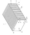
図1は、本実施例の燃料電池スタック10の外観を示す斜視図である。燃料電池スタック10は、図示する通り、単セル100を所定数積層して形成される。単セル100の積層数は、燃料電池スタック10に要求される出力に応じて任意に設定可能である。1つの単セル100は、1V程度の起電圧を生じる。各単セル100は、それぞれ固体高分子型燃料電池として形成されている。単セル100は、セパレータで酸素極、電解質膜、水素極をこの順序に挟んだ構造をなしている。燃料電池スタック10では、隣接する単セル100のセパレータは、それぞれ共有されている。単セル100の詳細構造については後述する。
A. Fuel cell stack configuration:
FIG. 1 is a perspective view showing an appearance of a
燃料電池スタック10は、一端からエンドプレート12、絶縁板16、集電板18、複数の単セル100、集電板20、絶縁板22、エンドプレート14の順に積層されて構成される。エンドプレート12、14は、剛性を確保するため、鋼等の金属によって形成されている。集電板18、20は、緻密質カーボンや銅板などガス不透過な導電性部材によって形成されている。絶縁板16、22は、ゴムや樹脂等の絶縁性部材によって形成されている。集電板18、20には、それぞれ出力端子19、21が設けられており、燃料電池スタック10で発電した電力を出力可能となっている。
The
一方のエンドプレート14には、燃料ガス供給口35や、燃料ガス排出口36や、酸化ガス供給口33や、酸化ガス排出口34や、冷却水供給口31や、冷却水排出口32が設けられている。燃料ガス供給口35から燃料電池スタック10に供給された燃料ガスは、エンドプレート12に向かって流れながら各単セル100に分配される。各単セル100に配分された燃料ガスは、図中の上方から下方に単セル100内の流路を流れた後、エンドプレート14側に流れ、燃料ガス排出口36から排出される。酸化ガスも同様に、酸化ガス供給口33から供給された後、エンドプレート12に向かって流れながら各単セル100に分配され、各単セル100内の流路を流れた後、酸化ガス排出口34から排出される。燃料電池スタック10は、このようなガスの流れを実現できるよう内部で各単セル100のガス流路が形成されている。
One
燃料電池スタック10の各単セル100を構成する電解質膜は、セパレータと接する周辺領域がシールされている。このシールは、単セル100内部から燃料ガスおよび酸化ガスが漏れ出し、両者が混合するのを防止する役割を果たす。燃料電池スタック10は、図示を省略したが、ボルトとナットで積層方向に所定の押圧力がかかった状態で締結されて保持される。押圧力を伴って積層状態を保持するためには、必ずしもボルトとナットを用いる必要はなく、例えばスタック収納ケースを用いるものとしてもよい。
The electrolyte membrane constituting each
図2は、単セル100の構造を示す斜視図である。単セル100は、固体高分子型燃料電池として構成されている。単セル100は、電解質膜132を水素極134と、酸素極136とで挟み込み、さらにその両側をセパレータ110、120で挟んだ構造を有している。図示の都合上、酸素極136は、電解質膜132に隠れた位置に存在する。水素極134、および、酸素極136は、後述するように、触媒層とガス拡散層とを積層させたガス拡散電極である。セパレータ110、120は、水素極134、酸素極136と対向する面に複数の凹凸状のリブが形成されている。セパレータ110、120が、水素極134、酸素極136を両側から挟み込むことによって、水素極134との間に燃料ガス流路112、酸素極136との間に酸化ガス流路122が形成される。
FIG. 2 is a perspective view showing the structure of the
セパレータ110、120は、両面にリブが形成されており、片面は水素極134との間で燃料ガス流路112を形成し、他面は隣接する単セル100が備える酸素極136との間で酸化ガス流路122を形成する。このように、セパレータ110、120は、ガス拡散電極との間でガス流路を形成するとともに、隣接するセル間で燃料ガスと酸化ガスの流れを分離する役割を果たしている。
The
電解質膜132は、固体高分子材料、例えば、フッ素系樹脂により形成されたプロトン伝導性のイオン交換膜であり、湿潤状態で良好な電気伝導性を示す。電解質膜132としては、例えばナフィオン膜(デュポン社製)などを適用することができる。
The
電解質膜132の表面には、触媒としての白金を塗布することにより、触媒層が形成されている。本実施例では、触媒としての白金を担持したカーボン粉を有機溶剤に分散させ、電解質溶液(例えば、Aldrich Chemical社、Nafion Solution)を適量添加してペースト化した上で、電解質膜132上にスクリーン印刷する方法で触媒を塗布した。この触媒層の形成方法は、他にも種々の方法を適用でき、例えば、上記触媒を担持したカーボン粉を含有するペーストを膜成形してシートを作製し、電解質膜132上にプレスするものとしてもよい。また、触媒には白金と他の金属からなる合金を用いることもできる。
A catalyst layer is formed on the surface of the
水素極134、および、酸素極136のガス拡散層は、炭素繊維を織成したカーボンクロスにより形成されている。ガス拡散層を炭素繊維からなるカーボンペーパ、または、カーボンフエルトにより形成するものとしてもよい。また、上述の触媒は、ガス拡散層と電解質膜132との間に介在しておればよいため、電解質膜132側に触媒を塗布する方法に代えて、ガス拡散層の電解質膜132と接する側に、触媒を塗布するものとしてもよい。
The gas diffusion layers of the
セパレータ110、120は、ガス不透過の導電性部材、例えば、カーボンを圧縮してガス不透過とした緻密質カーボンにより形成されている。セパレータ110、120は、その両面に、平行に配置された複数のリブが形成されている。リブは、必ずしも両面で平行に形成する必要はなく、面毎に直交するなど種々の角度で形成することができる。また、リブは、燃料ガスおよび酸化ガスの流路を形成可能な形状であれば、必ずしも平行な溝状である必要はない。
The
なお、本実施例の燃料電池スタック10では、単セル100の積層方向の端部(エンドプレート12、14の近傍)に積層されたセパレータ110、120のリブは、燃料ガスおよび酸化ガスの流路112、122の断面積が、他の部位に積層されたセパレータ110、120よりも大きくなるように形成されている(図示省略)。これは、以下の理由による。すなわち、燃料電池スタック10は、運転時に、単セル100の積層方向の中央部で温度が高く、端部で温度が低いという温度分布を有している。端部の単セル100は、大気への放熱により温度が低下しやすいからである。端部の単セル100では、温度低下に伴う蒸気圧の低下によって、生成水が滞留し易くなる。したがって、ガス流路の断面積を大きくして圧損を低減し、各ガスが各流路を流れやすくすることによって、過剰な生成水を除去するのである。
In the
セパレータ110、120には、その周辺部の2カ所に、円形断面の冷却水孔151、152が形成されている。この冷却水孔151、152は、単セル100を積層した際に、燃料電池スタック10を積層方向に貫通する冷却水路を形成する。
The
セパレータ110、120の各辺付近には、それぞれの辺に沿う細長い形状の燃料ガス孔153、154、および、酸化ガス孔155、156が形成されている。燃料ガス孔153、154、および、酸化ガス孔155、156は、単セル100を積層することによって燃料電池スタック10を形成した際に、燃料電池スタック10を積層方向に貫通する燃料ガス流路112、および、酸化ガス流路122を形成する。本実施例では、図2の上方の辺に沿って燃料ガス供給路、下方の辺に沿って燃料ガス排出路が形成される。また、左側の辺に沿って酸化ガス供給路、右側の辺に沿って酸化ガス排出路が形成される。
In the vicinity of each side of the
燃料電池スタック10の燃料ガス供給口35は、燃料ガス供給路につながっている。また、燃料ガス排出口36は、燃料ガス排出路につながっている。燃料ガス供給口35から供給された燃料ガスは、燃料ガス供給路を通じて各単セル100の燃料ガス流路112に流れ込む。そして、水素極134で所定の反応に供された後、燃料ガス排出路から燃料ガス排出口36に流出する。酸化ガスも同様の経路で流れる。
The fuel
燃料電池スタック10の酸化ガス供給口33は、酸化ガス供給路につながっている。また、酸化ガス排出口34は、酸化ガス排出路につながっている。酸化ガス供給口33から供給された酸化ガスは、酸化ガス供給路を通じて各単セル100の酸化ガス流路122に流れ込む。そして、酸素極136で所定の反応に供された後、酸化ガス排出路から酸化ガス排出口34に流出する。
The oxidizing
本実施例の燃料電池スタック10では、5つの単セル100ごとに1枚の割合で、冷却セパレータ140が設けられている。冷却セパレータ140は、単セル100を冷却する冷却水路を形成するためのセパレータである。冷却セパレータ140には、冷却水孔を連絡する葛折状の冷却水溝142が形成されている。セパレータ110、120のうち冷却セパレータ140と対向する面は、リブのないフラットな面となっており、冷却セパレータ140に設けられた溝は、セパレータ110、120との間で冷却水路を形成する。なお、セパレータ110、120、および、冷却セパレータ140は、緻密質カーボンの他、導電性を有する種々の材料によって形成することができる。例えば、剛性および伝熱性を重視して、銅合金やアルミニウム合金などの金属で形成してもよい。また、冷却セパレータ140を設ける割合は、燃料電池スタック10の要求出力に応じた単セル100の発熱量、冷却水の温度および流量などの条件に応じて冷却に適した範囲で設定することができる。
In the
B.第1実施例:
B1.電極構成:
図3は、第1実施例における単セル100の電極構成を示す説明図である。図3(a)は、燃料電池スタック10の中央部に積層された単セル(以下、中央セルと呼ぶ)の電極構成を示す断面図である。図3(b)は、燃料電池スタック10の端部に積層された単セル(以下、端セルと呼ぶ)の電極構成を示す断面図である。
B. First embodiment:
B1. Electrode configuration:
FIG. 3 is an explanatory diagram showing the electrode configuration of the
図3(a)に示すように、中央セルでは、電解質膜132の一方の面に触媒層134aとガス拡散層134bとを、この順序で積層することにより、水素極134が形成されている。また、電解質膜132のもう一方の面に触媒層136aとガス拡散層136bとを、この順序で積層することにより、酸素極136が形成されている。
As shown in FIG. 3A, in the central cell, the
一方、端セルでは、図3(b)に示すように、電解質膜132の一方の面に触媒層134cとガス拡散層134dとを、この順序で形成することにより、水素極134が形成されている。また、電解質膜132のもう一方の面に触媒層136cとガス拡散層136dとを、この順序で形成することにより、酸素極136が形成されている。
On the other hand, in the end cell, as shown in FIG. 3B, the
中央セルと端セルとでは、ガス拡散層の撥水性が異なる。そして、端セルのガス拡散層134d、136dの撥水性は、それぞれ中央セルのガス拡散層134b、136bの撥水性よりも低くしている。こうすることによって、生成水がガス拡散層表面に透過し易くすることができるので、ガスとともに排出され易くなる。したがって、ガス拡散層134d、136dのガス透過性を良好に維持することができる。
The water repellency of the gas diffusion layer is different between the center cell and the end cell. The water repellency of the end cell
また、中央セルおよび端セルの触媒層が担持する触媒の種類および比表面積は同じである。したがって、中央セルおよび端セルの触媒層の単位体積当たりの触媒能は同じである。 Moreover, the kind and specific surface area of the catalyst which the catalyst layer of a center cell and an end cell carry | support are the same. Therefore, the catalytic ability per unit volume of the catalyst layer of the center cell and the end cell is the same.
中央セルと端セルとでは、触媒層の厚さが異なる。そして、端セルの触媒層134c、136cの厚さは、それぞれ中央セルの触媒層134a、136aの厚さよりも厚く設定している。したがって、端セルの触媒層134c、136cの触媒能は、中央セルの触媒層134a、136aの触媒能よりも高い。本実施例では、端セルの触媒層134c、136cの厚さは、それぞれ中央セルの触媒層134a、136aの厚さの2倍であるものとした。なお、本実施例では、中央セルの触媒層134aの厚さと、触媒層136aの厚さ、あるいは、端セルの触媒層134cの厚さと、触媒層136cの厚さとは、それぞれ等しいものとしたが、任意に設定可能である。
The thickness of the catalyst layer is different between the center cell and the end cell. The thicknesses of the end cell catalyst layers 134c and 136c are set to be greater than the thicknesses of the center cell catalyst layers 134a and 136a, respectively. Therefore, the catalytic ability of the end cell catalyst layers 134c and 136c is higher than that of the central cell catalyst layers 134a and 136a. In this example, the thicknesses of the catalyst layers 134c and 136c in the end cells were twice the thicknesses of the catalyst layers 134a and 136a in the center cell, respectively. In the present embodiment, the thickness of the catalyst layer 134a in the central cell and the thickness of the
B2.効果:
図4は、第1実施例の効果を示す説明図である。図4(a)は、燃料電池スタック10を側面(単セル100の積層方向と直交する方向)から見た様子を模式的に示している。ここでは、単セル100の積層方向の両端から、それぞれ4枚の単セル100を端セルとした。図4(b)は、各触媒層の厚さの積層方向の分布を示している。図4(c)は、セル電圧の積層方向の分布を示している。図4(b)、(c)に、本実施例における各分布を、それぞれ実線で示した。また、これと併せて、従来の燃料電池スタックにおける各分布を、それぞれ破線で示した。従来の燃料電池スタックとは、図4(b)から分かるように、各触媒層の厚さが全て同じである単セルを複数積層させたものである。
B2. effect:
FIG. 4 is an explanatory diagram showing the effect of the first embodiment. FIG. 4A schematically shows a state in which the
図4(c)に示したように、従来の燃料電池スタックでは、単セルの積層方向の中央部で温度が高く、端部で温度が低いという温度分布に伴い、端セルのセル電圧が低下していた。これに対して、本実施例の燃料電池スタック10では、全ての単セル100でほぼ同一のセル電圧が得られた。
As shown in FIG. 4 (c), in the conventional fuel cell stack, the cell voltage of the end cell decreases with a temperature distribution in which the temperature is high at the center in the stacking direction of the single cells and the temperature is low at the end. Was. On the other hand, in the
なお、本実施例では、図4(b)に示したように、4枚の端セルの触媒層の厚さを同一としたが、図中に変形例として一点鎖線で示したように、触媒層の厚さを温度分布に応じて段階的に変化させてもよい。 In this embodiment, the thickness of the catalyst layers of the four end cells is the same as shown in FIG. 4 (b). However, as shown in FIG. The thickness of the layer may be changed stepwise depending on the temperature distribution.
以上説明した第1実施例の燃料電池スタック10によれば、端セルの触媒層の厚さを中央セルの触媒層の厚さよりも厚くしているので、端セルにおける反応の場を増加させ、触媒層全体としての触媒能を高めることができる。したがって、端セルの温度低下や、フラッディングによる燃料電池スタック10の発電性能の低下を抑制することができる。
According to the
C.第2実施例:
第1実施例では、中央セルと端セルとで、触媒層の厚さを変えた。第2実施例では、中央セルと端セルとで、触媒層が担持する触媒の比表面積を変える。
C. Second embodiment:
In the first example, the thickness of the catalyst layer was changed between the center cell and the end cell. In the second embodiment, the specific surface area of the catalyst supported by the catalyst layer is changed between the center cell and the end cell.
図5は、第2実施例における単セル100の電極構成を示す説明図である。第2実施例では、中央セルの触媒層134a、136aの厚さと、端セルの触媒層134e、136eの厚さとが同じである。そして、端セルの触媒層134e、136eが担持する触媒の比表面積が、中央セルの触媒層134a、136aが担持する触媒の比表面積よりも大きく設定されている。これ以外は、第1実施例と同じである。
FIG. 5 is an explanatory diagram showing an electrode configuration of the
以上説明した第2実施例の燃料電池によれば、端セルの触媒層が担持する触媒の比表面積を、中央セルの触媒層が担持する触媒の比表面積よりも大きくしているので、端セルにおける反応の場を増加させることができる。したがって、端セルの温度低下や、フラッディングによる燃料電池スタック10の発電性能の低下を抑制することができる。
According to the fuel cell of the second embodiment described above, the specific surface area of the catalyst supported by the catalyst layer of the end cell is made larger than the specific surface area of the catalyst supported by the catalyst layer of the central cell. The field of reaction in can be increased. Therefore, it is possible to suppress the temperature drop of the end cells and the power generation performance of the
D.変形例:
以上、本発明のいくつかの実施の形態について説明したが、本発明はこのような実施の形態になんら限定されるものではなく、その要旨を逸脱しない範囲内において種々なる態様での実施が可能である。例えば、以下のような変形例が可能である。
D. Variations:
As mentioned above, although several embodiment of this invention was described, this invention is not limited to such embodiment at all, and implementation in various aspects is possible within the range which does not deviate from the summary. It is. For example, the following modifications are possible.
D1.変形例1:
上記実施例では、単セル100の積層方向の温度分布に応じて、端セルの触媒層の厚さや、触媒層が担持する触媒の比表面積を、中央セルよりも大きくしたが、これに限られない。中央セルと端セルとで、触媒層が担持する触媒の種類を変えてもよい。すなわち、温度が低下しやすい端セルに、中央セルよりも触媒能の高い触媒を用いるようにしてもよい。
D1. Modification 1:
In the above embodiment, the thickness of the catalyst layer of the end cell and the specific surface area of the catalyst carried by the catalyst layer are made larger than those of the central cell according to the temperature distribution in the stacking direction of the
D2.変形例2:
上記実施例では、単セル100の積層方向の温度分布に応じて、端セルの触媒層の厚さや、触媒層が担持する触媒の比表面積を、中央セルよりも大きくした。変形例1では、各単セル100において、温度の面内分布に応じて触媒層の厚さを変える。
D2. Modification 2:
In the above example, the thickness of the catalyst layer of the end cell and the specific surface area of the catalyst carried by the catalyst layer were made larger than those of the central cell according to the temperature distribution in the stacking direction of the
図6は、変形例1における単セル100の電極構成の一例を示す説明図である。図の上段には、酸素極136側から見た単セル100の様子を示した。なお、図示の便宜上、セパレータ110や、ガス拡散層136bは省略して示した。図の下段には、図の上段のA−A断面における温度分布(面内分布)を示した。
FIG. 6 is an explanatory diagram showing an example of the electrode configuration of the
図の上段において、ハッチングを付した中央部の領域Mは、比較的温度の高い領域に対応する。クロスハッチングを付した周辺部の領域Nは、比較的温度の低い領域に対応する。そして、触媒層の厚さは、面内で不均一であり、領域Nの触媒層の厚さは、領域Mの触媒層の厚さよりも厚い。水素極134側も同様である。
In the upper part of the figure, a hatched central area M corresponds to a relatively high temperature area. The peripheral region N with cross-hatching corresponds to a region having a relatively low temperature. The thickness of the catalyst layer is not uniform in the plane, and the thickness of the catalyst layer in the region N is thicker than the thickness of the catalyst layer in the region M. The same applies to the
こうすることによっても、温度低下やフラッディングによる燃料電池スタック10の発電性能の低下を抑制することができる。
By so doing, it is also possible to suppress a decrease in the power generation performance of the
なお、変形例1では、領域Nと領域Mとで、触媒層の厚さを変えるものとしたが、触媒層が担持する触媒の比表面積や、触媒の種類を変えるようにしてもよい。また、変形例1では、温度分布に応じて、2種類の領域を設けたが、3種類以上の領域を設けるようにしてもよい。 In the first modification, the thickness of the catalyst layer is changed between the region N and the region M. However, the specific surface area of the catalyst carried by the catalyst layer and the type of the catalyst may be changed. In the first modification, two types of regions are provided according to the temperature distribution, but three or more types of regions may be provided.
D3.変形例3:
上記実施例では、水素極134と、酸素極136との両方に本発明を適用した例を示したが、いずれか一方に適用するようにしてもよい。ただし、少なくとも酸素極136に適用することが好ましい。一般に、水素極でのアノード反応よりも酸素極でのカソード反応の方が、反応速度が遅いからである。
D3. Modification 3:
In the above embodiment, the example in which the present invention is applied to both the
D4.変形例4:
上記第1実施例では、単セル100の両端の端セルに本発明を適用したが、いずれか一方の端セルに適用するようにしてもよい。
D4. Modification 4:
In the first embodiment, the present invention is applied to the end cells at both ends of the
また、触媒能の異なる触媒層を備える単セル100を混在させて積層するようにしてもよい。例えば、上記実施例の燃料電池スタック10では、冷却セパレータ140が設けられているから、これに隣接する単セル100は、温度が低下しやすい。したがって、冷却セパレータ140に隣接する単セル100の触媒層の厚さを厚くしたり、触媒層が担持する触媒の比表面積を増加させたり、触媒の種類を触媒能の高いものにしたりしてもよい。
Moreover, you may make it laminate | stack the
また、高温になり乾燥しやすい単セルに触媒能の高い触媒層を用いるようにしてもよい。こうすることによって、電解質膜の乾燥による燃料電池スタック10の発電性能の低下を抑制することができる。
Alternatively, a catalyst layer having a high catalytic ability may be used in a single cell that becomes hot and easily dried. By doing so, it is possible to suppress a decrease in power generation performance of the
D5.変形例5:
上記実施例および変形例1では、温度分布に応じて、触媒能に関連するパラメータ、すなわち、触媒層の厚さや、触媒層が担持する触媒の比表面積や、触媒の種類を、それぞれ独立に変える場合について説明したが、これらを組み合わせて変えるようにしてもよい。
D5. Modification 5:
In the above-described embodiment and modification example 1, the parameters related to the catalytic ability, that is, the thickness of the catalyst layer, the specific surface area of the catalyst supported by the catalyst layer, and the type of catalyst are changed independently according to the temperature distribution. Although the case has been described, these may be changed in combination.
D6.変形例6:
上記実施例では、本発明の燃料電池を固体高分子型燃料電池に適用したが、スタック構造を有する他の形式の燃料電池にも適用可能である。
D6. Modification 6:
In the above embodiment, the fuel cell of the present invention is applied to a polymer electrolyte fuel cell, but it can also be applied to other types of fuel cells having a stack structure.
D7.変形例7:
上記実施例および変形例では、温度が低下しやすい単セル、フラッディングが発生しやすい単セルに、触媒能が高い触媒層を適用した例を示したが、これに限られない。本発明は、一般に、燃料電池スタックにおいて、単セルにおける温度や、湿潤状態が最適でない場合でも燃料電池の発電性能の低下を抑制するものであるから、乾燥しやすい単セルに触媒能が高い触媒層を適用するようにしてもよい。
D7. Modification 7:
In the said Example and modification, although the example which applied the catalyst layer with high catalytic ability to the single cell which temperature falls easily, and the single cell which tends to generate | occur | produce flooding was shown, it is not restricted to this. In general, the present invention suppresses a decrease in power generation performance of a fuel cell even when the temperature or wet state in the single cell is not optimal in a fuel cell stack. Layers may be applied.
10...燃料電池スタック
12、14...エンドプレート
16、22...絶縁板
18、20...集電板
19、21...出力端子
31...冷却水供給口
32...冷却水排出口
33...酸化ガス供給口
34...酸化ガス排出口
35...燃料ガス供給口
36...燃料ガス排出口
100...単セル
110、120...セパレータ
112...燃料ガス流路
122...酸化ガス流路
132...電解質膜
134...水素極
134a、134c、134e...触媒層
134b、134d...ガス拡散層
136...酸素極
136a、136c、136e...触媒層
136b、136d...ガス拡散層
140...冷却セパレータ
142...冷却水溝
151、152...冷却水孔
153、154...燃料ガス孔
155、156...酸化ガス孔
10.
Claims (3)
少なくとも前記カソードは、反応を促進するための触媒を担持する触媒層を備え、
前記複数の単セルには、前記触媒の種類が同一であって、前記触媒単位重量当たりの面積が、他の単セルと異なる触媒層を備える単セルが混在しており、
前記スタック構造の積層方向の少なくとも一方の端部に、該端部以外に積層されたいずれかの単セルが備える触媒層よりも、前記触媒単位重量当たりの面積が大きい触媒層を備える単セルが積層されている、
燃料電池。 A fuel cell having a stack structure in which a plurality of single cells each having an anode and a cathode are laminated on both surfaces of a predetermined electrolyte membrane,
At least the cathode includes a catalyst layer supporting a catalyst for promoting the reaction,
The plurality of single cells, a same type of said catalyst, area per the unit weight of catalyst is a single cell comprising a catalyst layer different from other single cells are mixed,
A single cell provided with a catalyst layer having a larger area per unit weight of the catalyst than at a catalyst layer provided at any one of the stacked cells other than the end at at least one end in the stacking direction of the stack structure. Laminated,
Fuel cell.
前記スタック構造の積層方向の両端部に、該両端部以外に積層されたいずれかの単セルが備える触媒層よりも、前記触媒単位重量当たりの面積が大きい触媒層を備える単セルが積層されている、
燃料電池。 The fuel cell according to claim 1, wherein
At both ends of the stacking direction of the stack structure, than the catalyst layer included in any of the unit cells are stacked in addition to the both ends, the unit cell comprising a catalyst layer is larger area per the unit weight of catalyst is layered Yes,
Fuel cell.
前記電解質膜は、固体高分子膜である、燃料電池。 The fuel cell according to claim 1, wherein
The fuel cell, wherein the electrolyte membrane is a solid polymer membrane.
Priority Applications (6)
| Application Number | Priority Date | Filing Date | Title |
|---|---|---|---|
| JP2003376409A JP5124900B2 (en) | 2003-11-06 | 2003-11-06 | Fuel cell having a stack structure |
| US10/961,207 US7638227B2 (en) | 2003-11-06 | 2004-10-12 | Fuel cell having stack structure |
| CA2693522A CA2693522C (en) | 2003-11-06 | 2004-10-28 | Fuel cell with non-uniform catalyst |
| CA2486216A CA2486216C (en) | 2003-11-06 | 2004-10-28 | Fuel cell having stack structure |
| DE102004053589.2A DE102004053589B4 (en) | 2003-11-06 | 2004-11-05 | Fuel cell with a stack structure |
| CNB200410088310XA CN1319203C (en) | 2003-11-06 | 2004-11-08 | Fuel cell with laminated structure |
Applications Claiming Priority (1)
| Application Number | Priority Date | Filing Date | Title |
|---|---|---|---|
| JP2003376409A JP5124900B2 (en) | 2003-11-06 | 2003-11-06 | Fuel cell having a stack structure |
Publications (2)
| Publication Number | Publication Date |
|---|---|
| JP2005142001A JP2005142001A (en) | 2005-06-02 |
| JP5124900B2 true JP5124900B2 (en) | 2013-01-23 |
Family
ID=34567110
Family Applications (1)
| Application Number | Title | Priority Date | Filing Date |
|---|---|---|---|
| JP2003376409A Expired - Fee Related JP5124900B2 (en) | 2003-11-06 | 2003-11-06 | Fuel cell having a stack structure |
Country Status (5)
| Country | Link |
|---|---|
| US (1) | US7638227B2 (en) |
| JP (1) | JP5124900B2 (en) |
| CN (1) | CN1319203C (en) |
| CA (2) | CA2486216C (en) |
| DE (1) | DE102004053589B4 (en) |
Families Citing this family (13)
| Publication number | Priority date | Publication date | Assignee | Title |
|---|---|---|---|---|
| JP2006012476A (en) * | 2004-06-23 | 2006-01-12 | Nissan Motor Co Ltd | Membrane-electrode assembly for fuel cell |
| JP5135823B2 (en) * | 2007-02-21 | 2013-02-06 | パナソニック株式会社 | Fuel cell |
| DE102007021462B3 (en) * | 2007-05-08 | 2008-10-30 | Forschungszentrum Jülich GmbH | Heat sink for fuel cells |
| CN101621129B (en) * | 2008-06-30 | 2012-08-29 | 鸿富锦精密工业(深圳)有限公司 | Fuel battery pack |
| JP2010153267A (en) * | 2008-12-26 | 2010-07-08 | Equos Research Co Ltd | Fuel battery stack |
| JP5471008B2 (en) * | 2009-04-24 | 2014-04-16 | アイシン精機株式会社 | Fuel cell |
| US8206871B2 (en) * | 2009-07-10 | 2012-06-26 | GM Global Technology Operations LLC | Insulating layer for a fuel cell assembly |
| JP2013041673A (en) * | 2011-08-11 | 2013-02-28 | Nippon Soken Inc | Solid electrolyte fuel cell stack |
| JP6171134B2 (en) * | 2013-02-20 | 2017-08-02 | 本田技研工業株式会社 | Fuel cell stack |
| US20170062851A1 (en) * | 2015-04-24 | 2017-03-02 | GM Global Technology Operations LLC | Fuel cell stack end cells with improved diagnostic capabilities |
| CN107154503B (en) * | 2017-04-20 | 2019-09-27 | 清华大学 | A kind of long-life fuel cell galvanic pile module that can be quickly cold-started |
| US11894566B2 (en) | 2020-05-12 | 2024-02-06 | Robert Bosch Gmbh | Catalyst materials for a fuel cell stack |
| CN112909312B (en) * | 2021-01-21 | 2023-01-31 | 上海神力科技有限公司 | Proton exchange membrane fuel electric pile |
Family Cites Families (28)
| Publication number | Priority date | Publication date | Assignee | Title |
|---|---|---|---|---|
| US4567117A (en) * | 1982-07-08 | 1986-01-28 | Energy Research Corporation | Fuel cell employing non-uniform catalyst |
| US4851377A (en) | 1987-06-16 | 1989-07-25 | International Fuel Cells Corporation | Fuel cell, a fuel cell electrode, and a method for making a fuel cell electrode |
| JPH01151163A (en) | 1987-12-07 | 1989-06-13 | Fuji Electric Co Ltd | Fuel cell |
| US5068161A (en) * | 1990-03-30 | 1991-11-26 | Johnson Matthey Public Limited Company | Catalyst material |
| JPH04357673A (en) | 1991-03-25 | 1992-12-10 | Fuji Electric Co Ltd | Accumulated fuel cell |
| JPH05144443A (en) | 1991-11-21 | 1993-06-11 | Fuji Electric Co Ltd | Stacked fuel cell |
| JPH05205765A (en) * | 1992-01-23 | 1993-08-13 | Fuji Electric Co Ltd | Laminated fuel cell |
| JP3245929B2 (en) * | 1992-03-09 | 2002-01-15 | 株式会社日立製作所 | Fuel cell and its application device |
| EP0596366B1 (en) | 1992-11-05 | 1997-04-23 | Siemens Aktiengesellschaft | Method and device for removing water and inert gases from a fuel-cell battery |
| JPH06260207A (en) * | 1993-03-02 | 1994-09-16 | Fuji Electric Co Ltd | Stack of phosphate type fuel cell |
| JP3553101B2 (en) | 1993-03-15 | 2004-08-11 | 三菱重工業株式会社 | Solid polymer electrolyte fuel cell |
| GB9324101D0 (en) * | 1993-11-23 | 1994-01-12 | Johnson Matthey Plc | Improved manufacture of electrodes |
| JPH08148151A (en) * | 1994-11-17 | 1996-06-07 | Tokyo Gas Co Ltd | Fuel cell electrode and manufacture thereof |
| JPH0992322A (en) | 1995-09-27 | 1997-04-04 | Aqueous Res:Kk | Fuel cell stack |
| US5672439A (en) * | 1995-12-18 | 1997-09-30 | Ballard Power Systems, Inc. | Method and apparatus for reducing reactant crossover in an electrochemical fuel cell |
| JPH117971A (en) | 1997-06-18 | 1999-01-12 | Mitsubishi Electric Corp | Middle/large-capacity fuel-cell power generator |
| JP4205774B2 (en) | 1998-03-02 | 2009-01-07 | 本田技研工業株式会社 | Fuel cell |
| JP2000100457A (en) * | 1998-09-25 | 2000-04-07 | Matsushita Electric Ind Co Ltd | Fuel cell |
| JP4042241B2 (en) * | 1998-12-24 | 2008-02-06 | 三菱電機株式会社 | Fuel cell |
| JP3416578B2 (en) * | 1999-06-25 | 2003-06-16 | 三洋電機株式会社 | Solid polymer electrolyte fuel cell |
| JP3459597B2 (en) * | 1999-08-25 | 2003-10-20 | 三洋電機株式会社 | Polymer electrolyte fuel cell |
| DE19962686A1 (en) | 1999-12-23 | 2001-07-26 | Siemens Ag | Membrane electrode unit for a fuel cell and manufacturing process therefor |
| US6749892B2 (en) * | 2000-03-22 | 2004-06-15 | Samsung Electronics Co., Ltd. | Method for fabricating membrane-electrode assembly and fuel cell adopting the membrane-electrode assembly |
| JP3448550B2 (en) * | 2000-06-14 | 2003-09-22 | 三洋電機株式会社 | Polymer electrolyte fuel cell stack |
| JP4519375B2 (en) * | 2001-08-31 | 2010-08-04 | 三菱電機株式会社 | Fuel cell |
| JP3894109B2 (en) | 2002-11-28 | 2007-03-14 | トヨタ自動車株式会社 | Fuel cell |
| US7063905B2 (en) * | 2003-01-27 | 2006-06-20 | General Motors Corporation | Fuel cell H2 exhaust conversion |
| EP1623478A2 (en) * | 2003-05-15 | 2006-02-08 | Nissan Motor Company, Limited | Prevention of flooding of fuel cell stack |
-
2003
- 2003-11-06 JP JP2003376409A patent/JP5124900B2/en not_active Expired - Fee Related
-
2004
- 2004-10-12 US US10/961,207 patent/US7638227B2/en not_active Expired - Fee Related
- 2004-10-28 CA CA2486216A patent/CA2486216C/en not_active Expired - Fee Related
- 2004-10-28 CA CA2693522A patent/CA2693522C/en not_active Expired - Fee Related
- 2004-11-05 DE DE102004053589.2A patent/DE102004053589B4/en not_active Expired - Fee Related
- 2004-11-08 CN CNB200410088310XA patent/CN1319203C/en not_active Expired - Fee Related
Also Published As
| Publication number | Publication date |
|---|---|
| DE102004053589A1 (en) | 2005-06-23 |
| US20050106448A1 (en) | 2005-05-19 |
| US7638227B2 (en) | 2009-12-29 |
| CN1319203C (en) | 2007-05-30 |
| JP2005142001A (en) | 2005-06-02 |
| CN1614804A (en) | 2005-05-11 |
| DE102004053589B4 (en) | 2014-06-18 |
| CA2693522C (en) | 2012-07-10 |
| CA2486216C (en) | 2010-05-11 |
| CA2693522A1 (en) | 2005-05-06 |
| CA2486216A1 (en) | 2005-05-06 |
Similar Documents
| Publication | Publication Date | Title |
|---|---|---|
| CA2490877C (en) | Humidity controlled solid polymer electrolyte fuel cell assembly | |
| US5922485A (en) | Solid polymer electrolyte fuel cell | |
| JP4519375B2 (en) | Fuel cell | |
| JP5124900B2 (en) | Fuel cell having a stack structure | |
| JP3448550B2 (en) | Polymer electrolyte fuel cell stack | |
| JP2007059187A (en) | Fuel cell | |
| JP3354550B2 (en) | Polymer electrolyte fuel cell and polymer electrolyte fuel cell stack | |
| JP2001135326A (en) | Solid high molecular electrolyte fuel cell and stack of the same | |
| JP3500086B2 (en) | Fuel cell and fuel cell using the same | |
| JP4821111B2 (en) | Fuel cell | |
| JP3685039B2 (en) | Polymer electrolyte fuel cell system | |
| JP2005222720A (en) | Fuel cell | |
| JP5341321B2 (en) | Electrolyte membrane / electrode structure for polymer electrolyte fuel cells | |
| JP3875612B2 (en) | Fuel cell stack | |
| JPH05190193A (en) | Solid high polymeric electrolyte type fuel cell | |
| US20070003814A1 (en) | Polymer electrolyte membrane fuel cell stack | |
| JP2004185904A (en) | Fuel cell | |
| JP2008293808A (en) | Separator and fuel cell | |
| JPH06333581A (en) | Solid poly electrolyte fuel cell | |
| JP2004349013A (en) | Fuel cell stack | |
| JPH06333582A (en) | Solid polyelectrolyte fuel cell | |
| JP2002270197A (en) | High molecular electrolyte type fuel cull | |
| JP2009009750A (en) | Solid polymer fuel cell | |
| JP2009048905A (en) | Fuel cell | |
| JP2005190749A (en) | Membrane electrode assembly for fuel cell, and solid polymer fuel cell using it |
Legal Events
| Date | Code | Title | Description |
|---|---|---|---|
| A621 | Written request for application examination |
Free format text: JAPANESE INTERMEDIATE CODE: A621 Effective date: 20060830 |
|
| A977 | Report on retrieval |
Free format text: JAPANESE INTERMEDIATE CODE: A971007 Effective date: 20090224 |
|
| A131 | Notification of reasons for refusal |
Free format text: JAPANESE INTERMEDIATE CODE: A131 Effective date: 20100309 |
|
| A521 | Request for written amendment filed |
Free format text: JAPANESE INTERMEDIATE CODE: A523 Effective date: 20100423 |
|
| A131 | Notification of reasons for refusal |
Free format text: JAPANESE INTERMEDIATE CODE: A131 Effective date: 20110419 |
|
| A521 | Request for written amendment filed |
Free format text: JAPANESE INTERMEDIATE CODE: A523 Effective date: 20110527 |
|
| A02 | Decision of refusal |
Free format text: JAPANESE INTERMEDIATE CODE: A02 Effective date: 20120221 |
|
| A521 | Request for written amendment filed |
Free format text: JAPANESE INTERMEDIATE CODE: A523 Effective date: 20120510 |
|
| A911 | Transfer to examiner for re-examination before appeal (zenchi) |
Free format text: JAPANESE INTERMEDIATE CODE: A911 Effective date: 20120518 |
|
| A131 | Notification of reasons for refusal |
Free format text: JAPANESE INTERMEDIATE CODE: A131 Effective date: 20120717 |
|
| A521 | Request for written amendment filed |
Free format text: JAPANESE INTERMEDIATE CODE: A523 Effective date: 20120910 |
|
| TRDD | Decision of grant or rejection written | ||
| A01 | Written decision to grant a patent or to grant a registration (utility model) |
Free format text: JAPANESE INTERMEDIATE CODE: A01 Effective date: 20121002 |
|
| A01 | Written decision to grant a patent or to grant a registration (utility model) |
Free format text: JAPANESE INTERMEDIATE CODE: A01 |
|
| A61 | First payment of annual fees (during grant procedure) |
Free format text: JAPANESE INTERMEDIATE CODE: A61 Effective date: 20121015 |
|
| FPAY | Renewal fee payment (event date is renewal date of database) |
Free format text: PAYMENT UNTIL: 20151109 Year of fee payment: 3 |
|
| LAPS | Cancellation because of no payment of annual fees |