EP1136883A2 - Photographisches Bildherstellungssystem mit der Fähigkeit zur Aufzeichnung von Metadaten - Google Patents
Photographisches Bildherstellungssystem mit der Fähigkeit zur Aufzeichnung von Metadaten Download PDFInfo
- Publication number
- EP1136883A2 EP1136883A2 EP01200932A EP01200932A EP1136883A2 EP 1136883 A2 EP1136883 A2 EP 1136883A2 EP 01200932 A EP01200932 A EP 01200932A EP 01200932 A EP01200932 A EP 01200932A EP 1136883 A2 EP1136883 A2 EP 1136883A2
- Authority
- EP
- European Patent Office
- Prior art keywords
- dye
- image
- density
- infrared
- emulsion
- Prior art date
- Legal status (The legal status is an assumption and is not a legal conclusion. Google has not performed a legal analysis and makes no representation as to the accuracy of the status listed.)
- Withdrawn
Links
- 238000003384 imaging method Methods 0.000 title claims description 21
- 239000000975 dye Substances 0.000 claims abstract description 204
- -1 silver halide Chemical class 0.000 claims abstract description 133
- 229910052709 silver Inorganic materials 0.000 claims abstract description 62
- 239000004332 silver Substances 0.000 claims abstract description 62
- 238000010521 absorption reaction Methods 0.000 claims abstract description 27
- 239000013598 vector Substances 0.000 claims abstract description 10
- 239000001043 yellow dye Substances 0.000 claims abstract description 5
- AJDUTMFFZHIJEM-UHFFFAOYSA-N n-(9,10-dioxoanthracen-1-yl)-4-[4-[[4-[4-[(9,10-dioxoanthracen-1-yl)carbamoyl]phenyl]phenyl]diazenyl]phenyl]benzamide Chemical compound O=C1C2=CC=CC=C2C(=O)C2=C1C=CC=C2NC(=O)C(C=C1)=CC=C1C(C=C1)=CC=C1N=NC(C=C1)=CC=C1C(C=C1)=CC=C1C(=O)NC1=CC=CC2=C1C(=O)C1=CC=CC=C1C2=O AJDUTMFFZHIJEM-UHFFFAOYSA-N 0.000 claims abstract description 4
- 239000000839 emulsion Substances 0.000 claims description 123
- 230000003595 spectral effect Effects 0.000 claims description 49
- 238000000034 method Methods 0.000 claims description 46
- 230000035945 sensitivity Effects 0.000 claims description 34
- 230000008569 process Effects 0.000 claims description 29
- 239000010410 layer Substances 0.000 description 83
- 239000002019 doping agent Substances 0.000 description 39
- 230000006870 function Effects 0.000 description 30
- 229920001577 copolymer Polymers 0.000 description 29
- 239000000243 solution Substances 0.000 description 29
- 238000007792 addition Methods 0.000 description 28
- 239000000463 material Substances 0.000 description 27
- 230000001235 sensitizing effect Effects 0.000 description 26
- 229920000642 polymer Polymers 0.000 description 25
- 125000000217 alkyl group Chemical group 0.000 description 24
- 238000001556 precipitation Methods 0.000 description 24
- BQCADISMDOOEFD-UHFFFAOYSA-N Silver Chemical compound [Ag] BQCADISMDOOEFD-UHFFFAOYSA-N 0.000 description 23
- 230000009102 absorption Effects 0.000 description 23
- 108010010803 Gelatin Proteins 0.000 description 22
- FAPWRFPIFSIZLT-UHFFFAOYSA-M Sodium chloride Chemical compound [Na+].[Cl-] FAPWRFPIFSIZLT-UHFFFAOYSA-M 0.000 description 22
- 239000008273 gelatin Substances 0.000 description 22
- 229920000159 gelatin Polymers 0.000 description 22
- 235000019322 gelatine Nutrition 0.000 description 22
- 235000011852 gelatine desserts Nutrition 0.000 description 22
- SQGYOTSLMSWVJD-UHFFFAOYSA-N silver(1+) nitrate Chemical compound [Ag+].[O-]N(=O)=O SQGYOTSLMSWVJD-UHFFFAOYSA-N 0.000 description 22
- 229910052741 iridium Inorganic materials 0.000 description 20
- 239000006185 dispersion Substances 0.000 description 19
- 238000012545 processing Methods 0.000 description 19
- IOLCXVTUBQKXJR-UHFFFAOYSA-M potassium bromide Chemical compound [K+].[Br-] IOLCXVTUBQKXJR-UHFFFAOYSA-M 0.000 description 18
- 230000004044 response Effects 0.000 description 18
- 125000001424 substituent group Chemical group 0.000 description 18
- 125000003118 aryl group Chemical group 0.000 description 17
- 239000004816 latex Substances 0.000 description 17
- 229920000126 latex Polymers 0.000 description 17
- BAPJBEWLBFYGME-UHFFFAOYSA-N Methyl acrylate Chemical compound COC(=O)C=C BAPJBEWLBFYGME-UHFFFAOYSA-N 0.000 description 16
- 239000003795 chemical substances by application Substances 0.000 description 16
- 238000013461 design Methods 0.000 description 16
- 238000011161 development Methods 0.000 description 16
- 239000000203 mixture Substances 0.000 description 16
- 206010070834 Sensitisation Diseases 0.000 description 15
- 125000004432 carbon atom Chemical group C* 0.000 description 15
- XFHJDMUEHUHAJW-UHFFFAOYSA-N n-tert-butylprop-2-enamide Chemical compound CC(C)(C)NC(=O)C=C XFHJDMUEHUHAJW-UHFFFAOYSA-N 0.000 description 14
- 230000008313 sensitization Effects 0.000 description 14
- 239000000126 substance Substances 0.000 description 14
- 239000011248 coating agent Substances 0.000 description 12
- 238000000576 coating method Methods 0.000 description 12
- DOIRQSBPFJWKBE-UHFFFAOYSA-N dibutyl phthalate Chemical compound CCCCOC(=O)C1=CC=CC=C1C(=O)OCCCC DOIRQSBPFJWKBE-UHFFFAOYSA-N 0.000 description 12
- GKOZUEZYRPOHIO-UHFFFAOYSA-N iridium atom Chemical compound [Ir] GKOZUEZYRPOHIO-UHFFFAOYSA-N 0.000 description 11
- 229910001961 silver nitrate Inorganic materials 0.000 description 11
- 239000011780 sodium chloride Substances 0.000 description 11
- XMBWDFGMSWQBCA-UHFFFAOYSA-N hydrogen iodide Chemical compound I XMBWDFGMSWQBCA-UHFFFAOYSA-N 0.000 description 10
- 238000005406 washing Methods 0.000 description 10
- RLYUNPNLXMSXAX-UHFFFAOYSA-N 5-methylthiazole Chemical compound CC1=CN=CS1 RLYUNPNLXMSXAX-UHFFFAOYSA-N 0.000 description 9
- CPELXLSAUQHCOX-UHFFFAOYSA-M Bromide Chemical compound [Br-] CPELXLSAUQHCOX-UHFFFAOYSA-M 0.000 description 9
- YVIYNOINIIHOCG-UHFFFAOYSA-N gold(1+);sulfide Chemical compound [S-2].[Au+].[Au+] YVIYNOINIIHOCG-UHFFFAOYSA-N 0.000 description 9
- XEEYBQQBJWHFJM-UHFFFAOYSA-N iron Substances [Fe] XEEYBQQBJWHFJM-UHFFFAOYSA-N 0.000 description 9
- SCWKACOBHZIKDI-UHFFFAOYSA-N n-[3-(5-sulfanylidene-2h-tetrazol-1-yl)phenyl]acetamide Chemical compound CC(=O)NC1=CC=CC(N2C(N=NN2)=S)=C1 SCWKACOBHZIKDI-UHFFFAOYSA-N 0.000 description 9
- NLKNQRATVPKPDG-UHFFFAOYSA-M potassium iodide Chemical compound [K+].[I-] NLKNQRATVPKPDG-UHFFFAOYSA-M 0.000 description 9
- 239000010948 rhodium Substances 0.000 description 9
- 239000000725 suspension Substances 0.000 description 9
- 150000003568 thioethers Chemical class 0.000 description 9
- 229910021607 Silver chloride Inorganic materials 0.000 description 8
- PPBRXRYQALVLMV-UHFFFAOYSA-N Styrene Chemical compound C=CC1=CC=CC=C1 PPBRXRYQALVLMV-UHFFFAOYSA-N 0.000 description 8
- 125000003545 alkoxy group Chemical group 0.000 description 8
- 125000004104 aryloxy group Chemical group 0.000 description 8
- 230000015572 biosynthetic process Effects 0.000 description 8
- 238000006243 chemical reaction Methods 0.000 description 8
- 239000010931 gold Substances 0.000 description 8
- 229910052745 lead Inorganic materials 0.000 description 8
- 238000007639 printing Methods 0.000 description 8
- 238000011160 research Methods 0.000 description 8
- 229910052703 rhodium Inorganic materials 0.000 description 8
- HKZLPVFGJNLROG-UHFFFAOYSA-M silver monochloride Chemical compound [Cl-].[Ag+] HKZLPVFGJNLROG-UHFFFAOYSA-M 0.000 description 8
- 238000001228 spectrum Methods 0.000 description 8
- 238000004061 bleaching Methods 0.000 description 7
- 229910052737 gold Inorganic materials 0.000 description 7
- 239000003446 ligand Substances 0.000 description 7
- 239000000178 monomer Substances 0.000 description 7
- 230000000087 stabilizing effect Effects 0.000 description 7
- 229910052793 cadmium Inorganic materials 0.000 description 6
- 239000000460 chlorine Substances 0.000 description 6
- 230000000052 comparative effect Effects 0.000 description 6
- 150000001875 compounds Chemical class 0.000 description 6
- 239000010949 copper Substances 0.000 description 6
- 230000000694 effects Effects 0.000 description 6
- 229910052736 halogen Inorganic materials 0.000 description 6
- 125000000623 heterocyclic group Chemical group 0.000 description 6
- 229910052739 hydrogen Inorganic materials 0.000 description 6
- 239000001257 hydrogen Substances 0.000 description 6
- 125000004435 hydrogen atom Chemical group [H]* 0.000 description 6
- 150000002500 ions Chemical class 0.000 description 6
- BASFCYQUMIYNBI-UHFFFAOYSA-N platinum Substances [Pt] BASFCYQUMIYNBI-UHFFFAOYSA-N 0.000 description 6
- CHGSZSOJDJQCGO-UHFFFAOYSA-N ruthenium(2+);hexacyanide Chemical compound [Ru+2].N#[C-].N#[C-].N#[C-].N#[C-].N#[C-].N#[C-] CHGSZSOJDJQCGO-UHFFFAOYSA-N 0.000 description 6
- 229920000536 2-Acrylamido-2-methylpropane sulfonic acid Polymers 0.000 description 5
- XHZPRMZZQOIPDS-UHFFFAOYSA-N 2-Methyl-2-[(1-oxo-2-propenyl)amino]-1-propanesulfonic acid Chemical compound OS(=O)(=O)CC(C)(C)NC(=O)C=C XHZPRMZZQOIPDS-UHFFFAOYSA-N 0.000 description 5
- VVQNEPGJFQJSBK-UHFFFAOYSA-N Methyl methacrylate Chemical compound COC(=O)C(C)=C VVQNEPGJFQJSBK-UHFFFAOYSA-N 0.000 description 5
- 125000004423 acyloxy group Chemical group 0.000 description 5
- 238000004458 analytical method Methods 0.000 description 5
- CQEYYJKEWSMYFG-UHFFFAOYSA-N butyl acrylate Chemical compound CCCCOC(=O)C=C CQEYYJKEWSMYFG-UHFFFAOYSA-N 0.000 description 5
- 230000008859 change Effects 0.000 description 5
- 239000003086 colorant Substances 0.000 description 5
- 229910052802 copper Inorganic materials 0.000 description 5
- PCHJSUWPFVWCPO-UHFFFAOYSA-N gold Chemical compound [Au] PCHJSUWPFVWCPO-UHFFFAOYSA-N 0.000 description 5
- 150000004820 halides Chemical class 0.000 description 5
- 230000003993 interaction Effects 0.000 description 5
- 229910052697 platinum Inorganic materials 0.000 description 5
- 230000009467 reduction Effects 0.000 description 5
- 229910052702 rhenium Inorganic materials 0.000 description 5
- 150000003839 salts Chemical class 0.000 description 5
- 239000002904 solvent Substances 0.000 description 5
- 239000003381 stabilizer Substances 0.000 description 5
- 229910052725 zinc Inorganic materials 0.000 description 5
- PAYRUJLWNCNPSJ-UHFFFAOYSA-N Aniline Chemical compound NC1=CC=CC=C1 PAYRUJLWNCNPSJ-UHFFFAOYSA-N 0.000 description 4
- SOGAXMICEFXMKE-UHFFFAOYSA-N Butylmethacrylate Chemical compound CCCCOC(=O)C(C)=C SOGAXMICEFXMKE-UHFFFAOYSA-N 0.000 description 4
- 125000004414 alkyl thio group Chemical group 0.000 description 4
- 150000001412 amines Chemical class 0.000 description 4
- 239000007864 aqueous solution Substances 0.000 description 4
- 125000003917 carbamoyl group Chemical group [H]N([H])C(*)=O 0.000 description 4
- 229960002380 dibutyl phthalate Drugs 0.000 description 4
- 238000009826 distribution Methods 0.000 description 4
- 238000010893 electron trap Methods 0.000 description 4
- STVZJERGLQHEKB-UHFFFAOYSA-N ethylene glycol dimethacrylate Substances CC(=C)C(=O)OCCOC(=O)C(C)=C STVZJERGLQHEKB-UHFFFAOYSA-N 0.000 description 4
- 238000009472 formulation Methods 0.000 description 4
- 150000002367 halogens Chemical class 0.000 description 4
- 230000002209 hydrophobic effect Effects 0.000 description 4
- 239000011229 interlayer Substances 0.000 description 4
- 229910052751 metal Inorganic materials 0.000 description 4
- 239000002184 metal Substances 0.000 description 4
- 229910021645 metal ion Inorganic materials 0.000 description 4
- 239000003960 organic solvent Substances 0.000 description 4
- KDLHZDBZIXYQEI-UHFFFAOYSA-N palladium Substances [Pd] KDLHZDBZIXYQEI-UHFFFAOYSA-N 0.000 description 4
- 125000005420 sulfonamido group Chemical group S(=O)(=O)(N*)* 0.000 description 4
- 229910052717 sulfur Inorganic materials 0.000 description 4
- 125000000391 vinyl group Chemical group [H]C([*])=C([H])[H] 0.000 description 4
- 229920002554 vinyl polymer Polymers 0.000 description 4
- XLYOFNOQVPJJNP-UHFFFAOYSA-N water Substances O XLYOFNOQVPJJNP-UHFFFAOYSA-N 0.000 description 4
- GGZHVNZHFYCSEV-UHFFFAOYSA-N 1-Phenyl-5-mercaptotetrazole Chemical compound SC1=NN=NN1C1=CC=CC=C1 GGZHVNZHFYCSEV-UHFFFAOYSA-N 0.000 description 3
- WNOVBLHBCHOXKD-UHFFFAOYSA-N 2,3-bis(2,4,4-trimethylpentan-2-yl)benzene-1,4-diol Chemical compound CC(C)(C)CC(C)(C)C1=C(O)C=CC(O)=C1C(C)(C)CC(C)(C)C WNOVBLHBCHOXKD-UHFFFAOYSA-N 0.000 description 3
- HRPVXLWXLXDGHG-UHFFFAOYSA-N Acrylamide Chemical compound NC(=O)C=C HRPVXLWXLXDGHG-UHFFFAOYSA-N 0.000 description 3
- VEXZGXHMUGYJMC-UHFFFAOYSA-M Chloride anion Chemical compound [Cl-] VEXZGXHMUGYJMC-UHFFFAOYSA-M 0.000 description 3
- SNRUBQQJIBEYMU-UHFFFAOYSA-N Dodecane Chemical group CCCCCCCCCCCC SNRUBQQJIBEYMU-UHFFFAOYSA-N 0.000 description 3
- 241000015864 Protobothrops flavoviridis Species 0.000 description 3
- NINIDFKCEFEMDL-UHFFFAOYSA-N Sulfur Chemical compound [S] NINIDFKCEFEMDL-UHFFFAOYSA-N 0.000 description 3
- ZMZDMBWJUHKJPS-UHFFFAOYSA-M Thiocyanate anion Chemical compound [S-]C#N ZMZDMBWJUHKJPS-UHFFFAOYSA-M 0.000 description 3
- 125000002252 acyl group Chemical group 0.000 description 3
- 125000004442 acylamino group Chemical group 0.000 description 3
- 125000003342 alkenyl group Chemical group 0.000 description 3
- 125000004453 alkoxycarbonyl group Chemical group 0.000 description 3
- 125000005110 aryl thio group Chemical group 0.000 description 3
- 230000008901 benefit Effects 0.000 description 3
- 230000006835 compression Effects 0.000 description 3
- 238000007906 compression Methods 0.000 description 3
- LDHQCZJRKDOVOX-NSCUHMNNSA-N crotonic acid Chemical class C\C=C\C(O)=O LDHQCZJRKDOVOX-NSCUHMNNSA-N 0.000 description 3
- 238000010586 diagram Methods 0.000 description 3
- 125000003438 dodecyl group Chemical group [H]C([H])([H])C([H])([H])C([H])([H])C([H])([H])C([H])([H])C([H])([H])C([H])([H])C([H])([H])C([H])([H])C([H])([H])C([H])([H])C([H])([H])* 0.000 description 3
- 150000002148 esters Chemical class 0.000 description 3
- 125000005843 halogen group Chemical group 0.000 description 3
- 125000006343 heptafluoro propyl group Chemical group 0.000 description 3
- ZMZDMBWJUHKJPS-UHFFFAOYSA-N hydrogen thiocyanate Natural products SC#N ZMZDMBWJUHKJPS-UHFFFAOYSA-N 0.000 description 3
- 229910052742 iron Inorganic materials 0.000 description 3
- 238000011068 loading method Methods 0.000 description 3
- FQPSGWSUVKBHSU-UHFFFAOYSA-N methacrylamide Chemical class CC(=C)C(N)=O FQPSGWSUVKBHSU-UHFFFAOYSA-N 0.000 description 3
- 125000002496 methyl group Chemical group [H]C([H])([H])* 0.000 description 3
- 238000002156 mixing Methods 0.000 description 3
- 229910052757 nitrogen Inorganic materials 0.000 description 3
- 229910052760 oxygen Inorganic materials 0.000 description 3
- 229910052763 palladium Inorganic materials 0.000 description 3
- 125000005010 perfluoroalkyl group Chemical group 0.000 description 3
- 238000002360 preparation method Methods 0.000 description 3
- 229910052707 ruthenium Inorganic materials 0.000 description 3
- ADZWSOLPGZMUMY-UHFFFAOYSA-M silver bromide Chemical compound [Ag]Br ADZWSOLPGZMUMY-UHFFFAOYSA-M 0.000 description 3
- 239000002356 single layer Substances 0.000 description 3
- 150000003457 sulfones Chemical class 0.000 description 3
- 239000011593 sulfur Substances 0.000 description 3
- 239000004094 surface-active agent Substances 0.000 description 3
- 229910052716 thallium Inorganic materials 0.000 description 3
- 229910052723 transition metal Inorganic materials 0.000 description 3
- 150000003624 transition metals Chemical class 0.000 description 3
- 125000002023 trifluoromethyl group Chemical group FC(F)(F)* 0.000 description 3
- 229910052721 tungsten Inorganic materials 0.000 description 3
- 230000000007 visual effect Effects 0.000 description 3
- MYRTYDVEIRVNKP-UHFFFAOYSA-N 1,2-Divinylbenzene Chemical compound C=CC1=CC=CC=C1C=C MYRTYDVEIRVNKP-UHFFFAOYSA-N 0.000 description 2
- UZKWTJUDCOPSNM-UHFFFAOYSA-N 1-ethenoxybutane Chemical compound CCCCOC=C UZKWTJUDCOPSNM-UHFFFAOYSA-N 0.000 description 2
- VXQBJTKSVGFQOL-UHFFFAOYSA-N 2-(2-butoxyethoxy)ethyl acetate Chemical compound CCCCOCCOCCOC(C)=O VXQBJTKSVGFQOL-UHFFFAOYSA-N 0.000 description 2
- OEPOKWHJYJXUGD-UHFFFAOYSA-N 2-(3-phenylmethoxyphenyl)-1,3-thiazole-4-carbaldehyde Chemical compound O=CC1=CSC(C=2C=C(OCC=3C=CC=CC=3)C=CC=2)=N1 OEPOKWHJYJXUGD-UHFFFAOYSA-N 0.000 description 2
- JESXATFQYMPTNL-UHFFFAOYSA-N 2-ethenylphenol Chemical compound OC1=CC=CC=C1C=C JESXATFQYMPTNL-UHFFFAOYSA-N 0.000 description 2
- 229940044192 2-hydroxyethyl methacrylate Drugs 0.000 description 2
- 125000003903 2-propenyl group Chemical group [H]C([*])([H])C([H])=C([H])[H] 0.000 description 2
- QTBSBXVTEAMEQO-UHFFFAOYSA-N Acetic acid Chemical compound CC(O)=O QTBSBXVTEAMEQO-UHFFFAOYSA-N 0.000 description 2
- NLHHRLWOUZZQLW-UHFFFAOYSA-N Acrylonitrile Chemical compound C=CC#N NLHHRLWOUZZQLW-UHFFFAOYSA-N 0.000 description 2
- QGZKDVFQNNGYKY-UHFFFAOYSA-O Ammonium Chemical compound [NH4+] QGZKDVFQNNGYKY-UHFFFAOYSA-O 0.000 description 2
- CIWBSHSKHKDKBQ-JLAZNSOCSA-N Ascorbic acid Chemical compound OC[C@H](O)[C@H]1OC(=O)C(O)=C1O CIWBSHSKHKDKBQ-JLAZNSOCSA-N 0.000 description 2
- IJGRMHOSHXDMSA-UHFFFAOYSA-N Atomic nitrogen Chemical compound N#N IJGRMHOSHXDMSA-UHFFFAOYSA-N 0.000 description 2
- KCXVZYZYPLLWCC-UHFFFAOYSA-N EDTA Chemical compound OC(=O)CN(CC(O)=O)CCN(CC(O)=O)CC(O)=O KCXVZYZYPLLWCC-UHFFFAOYSA-N 0.000 description 2
- JIGUQPWFLRLWPJ-UHFFFAOYSA-N Ethyl acrylate Chemical compound CCOC(=O)C=C JIGUQPWFLRLWPJ-UHFFFAOYSA-N 0.000 description 2
- VZCYOOQTPOCHFL-OWOJBTEDSA-N Fumaric acid Chemical compound OC(=O)\C=C\C(O)=O VZCYOOQTPOCHFL-OWOJBTEDSA-N 0.000 description 2
- UFHFLCQGNIYNRP-UHFFFAOYSA-N Hydrogen Chemical compound [H][H] UFHFLCQGNIYNRP-UHFFFAOYSA-N 0.000 description 2
- BXUURYQQDJGIGA-UHFFFAOYSA-N N1C=NN2N=CC=C21 Chemical compound N1C=NN2N=CC=C21 BXUURYQQDJGIGA-UHFFFAOYSA-N 0.000 description 2
- UDFSJHJKINSRFV-UHFFFAOYSA-N N1N=CN2N=CC=C21 Chemical compound N1N=CN2N=CC=C21 UDFSJHJKINSRFV-UHFFFAOYSA-N 0.000 description 2
- MWUXSHHQAYIFBG-UHFFFAOYSA-N Nitric oxide Chemical group O=[N] MWUXSHHQAYIFBG-UHFFFAOYSA-N 0.000 description 2
- 239000004698 Polyethylene Substances 0.000 description 2
- WCUXLLCKKVVCTQ-UHFFFAOYSA-M Potassium chloride Chemical compound [Cl-].[K+] WCUXLLCKKVVCTQ-UHFFFAOYSA-M 0.000 description 2
- KJTLSVCANCCWHF-UHFFFAOYSA-N Ruthenium Chemical compound [Ru] KJTLSVCANCCWHF-UHFFFAOYSA-N 0.000 description 2
- 229910052770 Uranium Inorganic materials 0.000 description 2
- 238000000862 absorption spectrum Methods 0.000 description 2
- 230000001133 acceleration Effects 0.000 description 2
- 239000002253 acid Substances 0.000 description 2
- NIXOWILDQLNWCW-UHFFFAOYSA-N acrylic acid group Chemical group C(C=C)(=O)O NIXOWILDQLNWCW-UHFFFAOYSA-N 0.000 description 2
- 150000001336 alkenes Chemical class 0.000 description 2
- 125000004390 alkyl sulfonyl group Chemical group 0.000 description 2
- 125000003368 amide group Chemical group 0.000 description 2
- 150000001408 amides Chemical class 0.000 description 2
- 125000004397 aminosulfonyl group Chemical group NS(=O)(=O)* 0.000 description 2
- 229910052787 antimony Inorganic materials 0.000 description 2
- 229910052785 arsenic Inorganic materials 0.000 description 2
- 125000005162 aryl oxy carbonyl amino group Chemical group 0.000 description 2
- 125000004391 aryl sulfonyl group Chemical group 0.000 description 2
- QVGXLLKOCUKJST-UHFFFAOYSA-N atomic oxygen Chemical compound [O] QVGXLLKOCUKJST-UHFFFAOYSA-N 0.000 description 2
- 239000002585 base Substances 0.000 description 2
- 229910052797 bismuth Inorganic materials 0.000 description 2
- 239000007844 bleaching agent Substances 0.000 description 2
- FUSUHKVFWTUUBE-UHFFFAOYSA-N buten-2-one Chemical compound CC(=O)C=C FUSUHKVFWTUUBE-UHFFFAOYSA-N 0.000 description 2
- 229910052791 calcium Inorganic materials 0.000 description 2
- 239000011575 calcium Substances 0.000 description 2
- 125000001951 carbamoylamino group Chemical group C(N)(=O)N* 0.000 description 2
- 125000002915 carbonyl group Chemical group [*:2]C([*:1])=O 0.000 description 2
- 125000003178 carboxy group Chemical group [H]OC(*)=O 0.000 description 2
- 150000001732 carboxylic acid derivatives Chemical class 0.000 description 2
- YCIMNLLNPGFGHC-UHFFFAOYSA-N catechol Chemical compound OC1=CC=CC=C1O YCIMNLLNPGFGHC-UHFFFAOYSA-N 0.000 description 2
- 239000002738 chelating agent Substances 0.000 description 2
- ZLWLTDZLUVBSRJ-UHFFFAOYSA-K chembl2360149 Chemical compound [Na+].[Na+].[Na+].O=C1C(N=NC=2C=CC(=CC=2)S([O-])(=O)=O)=C(C(=O)[O-])NN1C1=CC=C(S([O-])(=O)=O)C=C1 ZLWLTDZLUVBSRJ-UHFFFAOYSA-K 0.000 description 2
- 239000003638 chemical reducing agent Substances 0.000 description 2
- 125000001309 chloro group Chemical group Cl* 0.000 description 2
- 229910052804 chromium Inorganic materials 0.000 description 2
- 238000012937 correction Methods 0.000 description 2
- 238000005859 coupling reaction Methods 0.000 description 2
- 238000005090 crystal field Methods 0.000 description 2
- 125000004093 cyano group Chemical group *C#N 0.000 description 2
- 230000006837 decompression Effects 0.000 description 2
- 230000003292 diminished effect Effects 0.000 description 2
- 125000001495 ethyl group Chemical group [H]C([H])([H])C([H])([H])* 0.000 description 2
- 238000011156 evaluation Methods 0.000 description 2
- LNTHITQWFMADLM-UHFFFAOYSA-N gallic acid Chemical compound OC(=O)C1=CC(O)=C(O)C(O)=C1 LNTHITQWFMADLM-UHFFFAOYSA-N 0.000 description 2
- 239000000499 gel Substances 0.000 description 2
- VOZRXNHHFUQHIL-UHFFFAOYSA-N glycidyl methacrylate Chemical compound CC(=C)C(=O)OCC1CO1 VOZRXNHHFUQHIL-UHFFFAOYSA-N 0.000 description 2
- 125000005844 heterocyclyloxy group Chemical group 0.000 description 2
- 125000004468 heterocyclylthio group Chemical group 0.000 description 2
- 229920001519 homopolymer Polymers 0.000 description 2
- 150000002430 hydrocarbons Chemical group 0.000 description 2
- 238000005286 illumination Methods 0.000 description 2
- 229910052738 indium Inorganic materials 0.000 description 2
- 230000005764 inhibitory process Effects 0.000 description 2
- 239000003999 initiator Substances 0.000 description 2
- LVHBHZANLOWSRM-UHFFFAOYSA-N itaconic acid Chemical class OC(=O)CC(=C)C(O)=O LVHBHZANLOWSRM-UHFFFAOYSA-N 0.000 description 2
- 239000007788 liquid Substances 0.000 description 2
- 229910052748 manganese Inorganic materials 0.000 description 2
- 238000004519 manufacturing process Methods 0.000 description 2
- 229910052753 mercury Inorganic materials 0.000 description 2
- 150000002739 metals Chemical class 0.000 description 2
- 125000001434 methanylylidene group Chemical group [H]C#[*] 0.000 description 2
- 125000000956 methoxy group Chemical group [H]C([H])([H])O* 0.000 description 2
- OMNKZBIFPJNNIO-UHFFFAOYSA-N n-(2-methyl-4-oxopentan-2-yl)prop-2-enamide Chemical compound CC(=O)CC(C)(C)NC(=O)C=C OMNKZBIFPJNNIO-UHFFFAOYSA-N 0.000 description 2
- PMJFVKWBSWWAKT-UHFFFAOYSA-N n-cyclohexylprop-2-enamide Chemical compound C=CC(=O)NC1CCCCC1 PMJFVKWBSWWAKT-UHFFFAOYSA-N 0.000 description 2
- 150000002825 nitriles Chemical class 0.000 description 2
- 230000003287 optical effect Effects 0.000 description 2
- 229910052762 osmium Inorganic materials 0.000 description 2
- 239000001301 oxygen Substances 0.000 description 2
- 125000002958 pentadecyl group Chemical group [H]C([*])([H])C([H])([H])C([H])([H])C([H])([H])C([H])([H])C([H])([H])C([H])([H])C([H])([H])C([H])([H])C([H])([H])C([H])([H])C([H])([H])C([H])([H])C([H])([H])C([H])([H])[H] 0.000 description 2
- PNJWIWWMYCMZRO-UHFFFAOYSA-N pent‐4‐en‐2‐one Natural products CC(=O)CC=C PNJWIWWMYCMZRO-UHFFFAOYSA-N 0.000 description 2
- 125000001997 phenyl group Chemical group [H]C1=C([H])C([H])=C(*)C([H])=C1[H] 0.000 description 2
- 229920000573 polyethylene Polymers 0.000 description 2
- 238000006116 polymerization reaction Methods 0.000 description 2
- BWHMMNNQKKPAPP-UHFFFAOYSA-L potassium carbonate Chemical compound [K+].[K+].[O-]C([O-])=O BWHMMNNQKKPAPP-UHFFFAOYSA-L 0.000 description 2
- USHAGKDGDHPEEY-UHFFFAOYSA-L potassium persulfate Chemical compound [K+].[K+].[O-]S(=O)(=O)OOS([O-])(=O)=O USHAGKDGDHPEEY-UHFFFAOYSA-L 0.000 description 2
- 230000005855 radiation Effects 0.000 description 2
- 238000010526 radical polymerization reaction Methods 0.000 description 2
- FSYKKLYZXJSNPZ-UHFFFAOYSA-N sarcosine Chemical compound C[NH2+]CC([O-])=O FSYKKLYZXJSNPZ-UHFFFAOYSA-N 0.000 description 2
- ZUNKMNLKJXRCDM-UHFFFAOYSA-N silver bromoiodide Chemical compound [Ag].IBr ZUNKMNLKJXRCDM-UHFFFAOYSA-N 0.000 description 2
- 239000011734 sodium Substances 0.000 description 2
- JHJLBTNAGRQEKS-UHFFFAOYSA-M sodium bromide Chemical compound [Na+].[Br-] JHJLBTNAGRQEKS-UHFFFAOYSA-M 0.000 description 2
- GEHJYWRUCIMESM-UHFFFAOYSA-L sodium sulfite Chemical compound [Na+].[Na+].[O-]S([O-])=O GEHJYWRUCIMESM-UHFFFAOYSA-L 0.000 description 2
- 239000007787 solid Substances 0.000 description 2
- 230000005236 sound signal Effects 0.000 description 2
- 125000004079 stearyl group Chemical group [H]C([*])([H])C([H])([H])C([H])([H])C([H])([H])C([H])([H])C([H])([H])C([H])([H])C([H])([H])C([H])([H])C([H])([H])C([H])([H])C([H])([H])C([H])([H])C([H])([H])C([H])([H])C([H])([H])C([H])([H])C([H])([H])[H] 0.000 description 2
- 238000003860 storage Methods 0.000 description 2
- 238000006467 substitution reaction Methods 0.000 description 2
- 125000000472 sulfonyl group Chemical group *S(*)(=O)=O 0.000 description 2
- JOXIMZWYDAKGHI-UHFFFAOYSA-N toluene-4-sulfonic acid Chemical compound CC1=CC=C(S(O)(=O)=O)C=C1 JOXIMZWYDAKGHI-UHFFFAOYSA-N 0.000 description 2
- VZCYOOQTPOCHFL-UHFFFAOYSA-N trans-butenedioic acid Natural products OC(=O)C=CC(O)=O VZCYOOQTPOCHFL-UHFFFAOYSA-N 0.000 description 2
- 238000012546 transfer Methods 0.000 description 2
- 229910052726 zirconium Inorganic materials 0.000 description 2
- GVEYRUKUJCHJSR-UHFFFAOYSA-N (4-azaniumyl-3-methylphenyl)-ethyl-(2-hydroxyethyl)azanium;sulfate Chemical compound OS(O)(=O)=O.OCCN(CC)C1=CC=C(N)C(C)=C1 GVEYRUKUJCHJSR-UHFFFAOYSA-N 0.000 description 1
- ILKZXYARHQNMEF-UHFFFAOYSA-N (4-azaniumyl-3-methylphenyl)-ethyl-(2-methoxyethyl)azanium;4-methylbenzenesulfonate Chemical compound CC1=CC=C(S(O)(=O)=O)C=C1.CC1=CC=C(S(O)(=O)=O)C=C1.COCCN(CC)C1=CC=C(N)C(C)=C1 ILKZXYARHQNMEF-UHFFFAOYSA-N 0.000 description 1
- NQQRXZOPZBKCNF-NSCUHMNNSA-N (e)-but-2-enamide Chemical compound C\C=C\C(N)=O NQQRXZOPZBKCNF-NSCUHMNNSA-N 0.000 description 1
- WBYWAXJHAXSJNI-VOTSOKGWSA-M .beta-Phenylacrylic acid Natural products [O-]C(=O)\C=C\C1=CC=CC=C1 WBYWAXJHAXSJNI-VOTSOKGWSA-M 0.000 description 1
- SVHAMPNLOLKSFU-UHFFFAOYSA-N 1,2,2-trichloroethenylbenzene Chemical compound ClC(Cl)=C(Cl)C1=CC=CC=C1 SVHAMPNLOLKSFU-UHFFFAOYSA-N 0.000 description 1
- PGXOMORTLJMALN-UHFFFAOYSA-N 1,4,5-trimethyl-1,2,4-triazol-4-ium-3-thiolate Chemical compound CC=1N(C)C([S-])=N[N+]=1C PGXOMORTLJMALN-UHFFFAOYSA-N 0.000 description 1
- 150000005208 1,4-dihydroxybenzenes Chemical class 0.000 description 1
- CBCKQZAAMUWICA-UHFFFAOYSA-N 1,4-phenylenediamine Chemical compound NC1=CC=C(N)C=C1 CBCKQZAAMUWICA-UHFFFAOYSA-N 0.000 description 1
- KAMCBFNNGGVPPW-UHFFFAOYSA-N 1-(ethenylsulfonylmethoxymethylsulfonyl)ethene Chemical compound C=CS(=O)(=O)COCS(=O)(=O)C=C KAMCBFNNGGVPPW-UHFFFAOYSA-N 0.000 description 1
- DNJRKFKAFWSXSE-UHFFFAOYSA-N 1-chloro-2-ethenoxyethane Chemical compound ClCCOC=C DNJRKFKAFWSXSE-UHFFFAOYSA-N 0.000 description 1
- HWCLMKDWXUGDKL-UHFFFAOYSA-N 1-ethenoxy-2-ethoxyethane Chemical compound CCOCCOC=C HWCLMKDWXUGDKL-UHFFFAOYSA-N 0.000 description 1
- GXZPMXGRNUXGHN-UHFFFAOYSA-N 1-ethenoxy-2-methoxyethane Chemical compound COCCOC=C GXZPMXGRNUXGHN-UHFFFAOYSA-N 0.000 description 1
- OSSNTDFYBPYIEC-UHFFFAOYSA-N 1-ethenylimidazole Chemical compound C=CN1C=CN=C1 OSSNTDFYBPYIEC-UHFFFAOYSA-N 0.000 description 1
- HECLRDQVFMWTQS-RGOKHQFPSA-N 1755-01-7 Chemical compound C1[C@H]2[C@@H]3CC=C[C@@H]3[C@@H]1C=C2 HECLRDQVFMWTQS-RGOKHQFPSA-N 0.000 description 1
- JAAIPIWKKXCNOC-UHFFFAOYSA-N 1h-tetrazol-1-ium-5-thiolate Chemical class SC1=NN=NN1 JAAIPIWKKXCNOC-UHFFFAOYSA-N 0.000 description 1
- CISIJYCKDJSTMX-UHFFFAOYSA-N 2,2-dichloroethenylbenzene Chemical compound ClC(Cl)=CC1=CC=CC=C1 CISIJYCKDJSTMX-UHFFFAOYSA-N 0.000 description 1
- PWESSVUYESFKBH-UHFFFAOYSA-N 2,2-dimethoxyethenylbenzene Chemical compound COC(OC)=CC1=CC=CC=C1 PWESSVUYESFKBH-UHFFFAOYSA-N 0.000 description 1
- LCPVQAHEFVXVKT-UHFFFAOYSA-N 2-(2,4-difluorophenoxy)pyridin-3-amine Chemical compound NC1=CC=CN=C1OC1=CC=C(F)C=C1F LCPVQAHEFVXVKT-UHFFFAOYSA-N 0.000 description 1
- OZAIFHULBGXAKX-UHFFFAOYSA-N 2-(2-cyanopropan-2-yldiazenyl)-2-methylpropanenitrile Chemical compound N#CC(C)(C)N=NC(C)(C)C#N OZAIFHULBGXAKX-UHFFFAOYSA-N 0.000 description 1
- WULAHPYSGCVQHM-UHFFFAOYSA-N 2-(2-ethenoxyethoxy)ethanol Chemical compound OCCOCCOC=C WULAHPYSGCVQHM-UHFFFAOYSA-N 0.000 description 1
- SMZOUWXMTYCWNB-UHFFFAOYSA-N 2-(2-methoxy-5-methylphenyl)ethanamine Chemical compound COC1=CC=C(C)C=C1CCN SMZOUWXMTYCWNB-UHFFFAOYSA-N 0.000 description 1
- PRAMZQXXPOLCIY-UHFFFAOYSA-N 2-(2-methylprop-2-enoyloxy)ethanesulfonic acid Chemical compound CC(=C)C(=O)OCCS(O)(=O)=O PRAMZQXXPOLCIY-UHFFFAOYSA-N 0.000 description 1
- IBDVWXAVKPRHCU-UHFFFAOYSA-N 2-(2-methylprop-2-enoyloxy)ethyl 3-oxobutanoate Chemical compound CC(=O)CC(=O)OCCOC(=O)C(C)=C IBDVWXAVKPRHCU-UHFFFAOYSA-N 0.000 description 1
- JAHNSTQSQJOJLO-UHFFFAOYSA-N 2-(3-fluorophenyl)-1h-imidazole Chemical compound FC1=CC=CC(C=2NC=CN=2)=C1 JAHNSTQSQJOJLO-UHFFFAOYSA-N 0.000 description 1
- UIUSRIAANRCPGF-UHFFFAOYSA-N 2-(ethenoxymethyl)oxolane Chemical compound C=COCC1CCCO1 UIUSRIAANRCPGF-UHFFFAOYSA-N 0.000 description 1
- RCSBILYQLVXLJG-UHFFFAOYSA-N 2-Propenyl hexanoate Chemical compound CCCCCC(=O)OCC=C RCSBILYQLVXLJG-UHFFFAOYSA-N 0.000 description 1
- UOMQUZPKALKDCA-UHFFFAOYSA-K 2-[2-[bis(carboxylatomethyl)amino]ethyl-(carboxymethyl)amino]acetate;iron(3+) Chemical compound [Fe+3].OC(=O)CN(CC([O-])=O)CCN(CC([O-])=O)CC([O-])=O UOMQUZPKALKDCA-UHFFFAOYSA-K 0.000 description 1
- VCYCUECVHJJFIQ-UHFFFAOYSA-N 2-[3-(benzotriazol-2-yl)-4-hydroxyphenyl]ethyl 2-methylprop-2-enoate Chemical compound CC(=C)C(=O)OCCC1=CC=C(O)C(N2N=C3C=CC=CC3=N2)=C1 VCYCUECVHJJFIQ-UHFFFAOYSA-N 0.000 description 1
- XSHISXQEKIKSGC-UHFFFAOYSA-N 2-aminoethyl 2-methylprop-2-enoate;hydron;chloride Chemical compound Cl.CC(=C)C(=O)OCCN XSHISXQEKIKSGC-UHFFFAOYSA-N 0.000 description 1
- CDAWCLOXVUBKRW-UHFFFAOYSA-N 2-aminophenol Chemical class NC1=CC=CC=C1O CDAWCLOXVUBKRW-UHFFFAOYSA-N 0.000 description 1
- JKFYKCYQEWQPTM-UHFFFAOYSA-N 2-azaniumyl-2-(4-fluorophenyl)acetate Chemical compound OC(=O)C(N)C1=CC=C(F)C=C1 JKFYKCYQEWQPTM-UHFFFAOYSA-N 0.000 description 1
- SZTBMYHIYNGYIA-UHFFFAOYSA-N 2-chloroacrylic acid Chemical compound OC(=O)C(Cl)=C SZTBMYHIYNGYIA-UHFFFAOYSA-N 0.000 description 1
- SBYMUDUGTIKLCR-UHFFFAOYSA-N 2-chloroethenylbenzene Chemical compound ClC=CC1=CC=CC=C1 SBYMUDUGTIKLCR-UHFFFAOYSA-N 0.000 description 1
- MENUHMSZHZBYMK-UHFFFAOYSA-N 2-cyclohexylethenylbenzene Chemical compound C1CCCCC1C=CC1=CC=CC=C1 MENUHMSZHZBYMK-UHFFFAOYSA-N 0.000 description 1
- JWCDUUFOAZFFMX-UHFFFAOYSA-N 2-ethenoxy-n,n-dimethylethanamine Chemical compound CN(C)CCOC=C JWCDUUFOAZFFMX-UHFFFAOYSA-N 0.000 description 1
- VUIWJRYTWUGOOF-UHFFFAOYSA-N 2-ethenoxyethanol Chemical compound OCCOC=C VUIWJRYTWUGOOF-UHFFFAOYSA-N 0.000 description 1
- XUDBVJCTLZTSDC-UHFFFAOYSA-N 2-ethenylbenzoic acid Chemical compound OC(=O)C1=CC=CC=C1C=C XUDBVJCTLZTSDC-UHFFFAOYSA-N 0.000 description 1
- WROUWQQRXUBECT-UHFFFAOYSA-N 2-ethylacrylic acid Chemical compound CCC(=C)C(O)=O WROUWQQRXUBECT-UHFFFAOYSA-N 0.000 description 1
- KBKNKFIRGXQLDB-UHFFFAOYSA-N 2-fluoroethenylbenzene Chemical compound FC=CC1=CC=CC=C1 KBKNKFIRGXQLDB-UHFFFAOYSA-N 0.000 description 1
- OZPOYKXYJOHGCW-UHFFFAOYSA-N 2-iodoethenylbenzene Chemical compound IC=CC1=CC=CC=C1 OZPOYKXYJOHGCW-UHFFFAOYSA-N 0.000 description 1
- CTHJQRHPNQEPAB-UHFFFAOYSA-N 2-methoxyethenylbenzene Chemical compound COC=CC1=CC=CC=C1 CTHJQRHPNQEPAB-UHFFFAOYSA-N 0.000 description 1
- OPRIWFSSXKQMPB-UHFFFAOYSA-N 2-methyl-2-(prop-2-enoylamino)propane-1-sulfonic acid;sodium Chemical compound [Na].OS(=O)(=O)CC(C)(C)NC(=O)C=C OPRIWFSSXKQMPB-UHFFFAOYSA-N 0.000 description 1
- IZFHMLDRUVYBGK-UHFFFAOYSA-N 2-methylene-3-methylsuccinic acid Chemical compound OC(=O)C(C)C(=C)C(O)=O IZFHMLDRUVYBGK-UHFFFAOYSA-N 0.000 description 1
- BTOVVHWKPVSLBI-UHFFFAOYSA-N 2-methylprop-1-enylbenzene Chemical compound CC(C)=CC1=CC=CC=C1 BTOVVHWKPVSLBI-UHFFFAOYSA-N 0.000 description 1
- FMFHUEMLVAIBFI-UHFFFAOYSA-N 2-phenylethenyl acetate Chemical compound CC(=O)OC=CC1=CC=CC=C1 FMFHUEMLVAIBFI-UHFFFAOYSA-N 0.000 description 1
- TZTLYMAZBRFTJA-UHFFFAOYSA-N 2-prop-2-enoyloxyethanesulfonic acid;sodium Chemical compound [Na].OS(=O)(=O)CCOC(=O)C=C TZTLYMAZBRFTJA-UHFFFAOYSA-N 0.000 description 1
- ORNUPNRNNSVZTC-UHFFFAOYSA-N 2-vinylthiophene Chemical compound C=CC1=CC=CS1 ORNUPNRNNSVZTC-UHFFFAOYSA-N 0.000 description 1
- HKADMMFLLPJEAG-UHFFFAOYSA-N 3,3,3-trifluoroprop-1-enylbenzene Chemical compound FC(F)(F)C=CC1=CC=CC=C1 HKADMMFLLPJEAG-UHFFFAOYSA-N 0.000 description 1
- 125000004189 3,4-dichlorophenyl group Chemical group [H]C1=C([H])C(Cl)=C(Cl)C([H])=C1* 0.000 description 1
- YVAQHFNMILVVNE-UHFFFAOYSA-N 3-(prop-2-enoylamino)propanoic acid Chemical compound OC(=O)CCNC(=O)C=C YVAQHFNMILVVNE-UHFFFAOYSA-N 0.000 description 1
- JBTDFRNUVWFUGL-UHFFFAOYSA-N 3-aminopropyl carbamimidothioate;dihydrobromide Chemical compound Br.Br.NCCCSC(N)=N JBTDFRNUVWFUGL-UHFFFAOYSA-N 0.000 description 1
- IWTYTFSSTWXZFU-UHFFFAOYSA-N 3-chloroprop-1-enylbenzene Chemical compound ClCC=CC1=CC=CC=C1 IWTYTFSSTWXZFU-UHFFFAOYSA-N 0.000 description 1
- FWLGYSGTHHKRMZ-UHFFFAOYSA-N 3-ethenoxy-2,2-dimethylbutane Chemical compound CC(C)(C)C(C)OC=C FWLGYSGTHHKRMZ-UHFFFAOYSA-N 0.000 description 1
- XHULUQRDNLRXPF-UHFFFAOYSA-N 3-ethenyl-1,3-oxazolidin-2-id-4-one Chemical compound C(=C)N1[CH-]OCC1=O XHULUQRDNLRXPF-UHFFFAOYSA-N 0.000 description 1
- XOQMWEWYWXJOAN-UHFFFAOYSA-N 3-methyl-3-(prop-2-enoylamino)butanoic acid Chemical compound OC(=O)CC(C)(C)NC(=O)C=C XOQMWEWYWXJOAN-UHFFFAOYSA-N 0.000 description 1
- CEBRPXLXYCFYGU-UHFFFAOYSA-N 3-methylbut-1-enylbenzene Chemical compound CC(C)C=CC1=CC=CC=C1 CEBRPXLXYCFYGU-UHFFFAOYSA-N 0.000 description 1
- AIMDYNJRXHEXEL-UHFFFAOYSA-N 3-phenylprop-1-enylbenzene Chemical compound C=1C=CC=CC=1CC=CC1=CC=CC=C1 AIMDYNJRXHEXEL-UHFFFAOYSA-N 0.000 description 1
- VFXXTYGQYWRHJP-UHFFFAOYSA-N 4,4'-azobis(4-cyanopentanoic acid) Chemical compound OC(=O)CCC(C)(C#N)N=NC(C)(CCC(O)=O)C#N VFXXTYGQYWRHJP-UHFFFAOYSA-N 0.000 description 1
- JLBJTVDPSNHSKJ-UHFFFAOYSA-N 4-Methylstyrene Chemical compound CC1=CC=C(C=C)C=C1 JLBJTVDPSNHSKJ-UHFFFAOYSA-N 0.000 description 1
- DBCAQXHNJOFNGC-UHFFFAOYSA-N 4-bromo-1,1,1-trifluorobutane Chemical compound FC(F)(F)CCCBr DBCAQXHNJOFNGC-UHFFFAOYSA-N 0.000 description 1
- 125000004801 4-cyanophenyl group Chemical group [H]C1=C([H])C(C#N)=C([H])C([H])=C1* 0.000 description 1
- GVGQXTJQMNTHJX-UHFFFAOYSA-N 4-ethenyl-1-methoxy-2-methylbenzene Chemical compound COC1=CC=C(C=C)C=C1C GVGQXTJQMNTHJX-UHFFFAOYSA-N 0.000 description 1
- XTBFKMDOQMQYPP-UHFFFAOYSA-N 4-n,4-n-diethylbenzene-1,4-diamine;hydron;chloride Chemical compound Cl.CCN(CC)C1=CC=C(N)C=C1 XTBFKMDOQMQYPP-UHFFFAOYSA-N 0.000 description 1
- 125000002373 5 membered heterocyclic group Chemical group 0.000 description 1
- GRQHIHQAHQXDLY-UHFFFAOYSA-N 5,5-dimethyloct-1-ene Chemical compound CCCC(C)(C)CCC=C GRQHIHQAHQXDLY-UHFFFAOYSA-N 0.000 description 1
- 229920002126 Acrylic acid copolymer Polymers 0.000 description 1
- 241001479434 Agfa Species 0.000 description 1
- QGZKDVFQNNGYKY-UHFFFAOYSA-N Ammonia Chemical compound N QGZKDVFQNNGYKY-UHFFFAOYSA-N 0.000 description 1
- 239000004342 Benzoyl peroxide Substances 0.000 description 1
- OMPJBNCRMGITSC-UHFFFAOYSA-N Benzoylperoxide Chemical compound C=1C=CC=CC=1C(=O)OOC(=O)C1=CC=CC=C1 OMPJBNCRMGITSC-UHFFFAOYSA-N 0.000 description 1
- OYPRJOBELJOOCE-UHFFFAOYSA-N Calcium Chemical compound [Ca] OYPRJOBELJOOCE-UHFFFAOYSA-N 0.000 description 1
- 229910052684 Cerium Inorganic materials 0.000 description 1
- WBYWAXJHAXSJNI-SREVYHEPSA-N Cinnamic acid Chemical compound OC(=O)\C=C/C1=CC=CC=C1 WBYWAXJHAXSJNI-SREVYHEPSA-N 0.000 description 1
- 229910017518 Cu Zn Inorganic materials 0.000 description 1
- XFXPMWWXUTWYJX-UHFFFAOYSA-N Cyanide Chemical compound N#[C-] XFXPMWWXUTWYJX-UHFFFAOYSA-N 0.000 description 1
- 229920001174 Diethylhydroxylamine Polymers 0.000 description 1
- 239000004593 Epoxy Substances 0.000 description 1
- USXDFAGDIOXNML-UHFFFAOYSA-N Fulminate Chemical compound [O-][N+]#[C-] USXDFAGDIOXNML-UHFFFAOYSA-N 0.000 description 1
- VEXZGXHMUGYJMC-UHFFFAOYSA-N Hydrochloric acid Chemical compound Cl VEXZGXHMUGYJMC-UHFFFAOYSA-N 0.000 description 1
- WOBHKFSMXKNTIM-UHFFFAOYSA-N Hydroxyethyl methacrylate Chemical compound CC(=C)C(=O)OCCO WOBHKFSMXKNTIM-UHFFFAOYSA-N 0.000 description 1
- WHXSMMKQMYFTQS-UHFFFAOYSA-N Lithium Chemical compound [Li] WHXSMMKQMYFTQS-UHFFFAOYSA-N 0.000 description 1
- 241000409201 Luina Species 0.000 description 1
- CERQOIWHTDAKMF-UHFFFAOYSA-N Methacrylic acid Chemical compound CC(=C)C(O)=O CERQOIWHTDAKMF-UHFFFAOYSA-N 0.000 description 1
- KWKVAGQCDSHWFK-VNKDHWASSA-N Methyl sorbate Chemical compound COC(=O)\C=C\C=C\C KWKVAGQCDSHWFK-VNKDHWASSA-N 0.000 description 1
- WHNWPMSKXPGLAX-UHFFFAOYSA-N N-Vinyl-2-pyrrolidone Chemical compound C=CN1CCCC1=O WHNWPMSKXPGLAX-UHFFFAOYSA-N 0.000 description 1
- MUBZPKHOEPUJKR-UHFFFAOYSA-N Oxalic acid Chemical class OC(=O)C(O)=O MUBZPKHOEPUJKR-UHFFFAOYSA-N 0.000 description 1
- 235000010627 Phaseolus vulgaris Nutrition 0.000 description 1
- 244000046052 Phaseolus vulgaris Species 0.000 description 1
- 229920002319 Poly(methyl acrylate) Polymers 0.000 description 1
- 239000004793 Polystyrene Substances 0.000 description 1
- OFOBLEOULBTSOW-UHFFFAOYSA-N Propanedioic acid Natural products OC(=O)CC(O)=O OFOBLEOULBTSOW-UHFFFAOYSA-N 0.000 description 1
- XBDQKXXYIPTUBI-UHFFFAOYSA-M Propionate Chemical compound CCC([O-])=O XBDQKXXYIPTUBI-UHFFFAOYSA-M 0.000 description 1
- 108010077895 Sarcosine Proteins 0.000 description 1
- VYPSYNLAJGMNEJ-UHFFFAOYSA-N Silicium dioxide Chemical compound O=[Si]=O VYPSYNLAJGMNEJ-UHFFFAOYSA-N 0.000 description 1
- 229910021612 Silver iodide Inorganic materials 0.000 description 1
- FOIXSVOLVBLSDH-UHFFFAOYSA-N Silver ion Chemical class [Ag+] FOIXSVOLVBLSDH-UHFFFAOYSA-N 0.000 description 1
- QAOWNCQODCNURD-UHFFFAOYSA-L Sulfate Chemical compound [O-]S([O-])(=O)=O QAOWNCQODCNURD-UHFFFAOYSA-L 0.000 description 1
- LSNNMFCWUKXFEE-UHFFFAOYSA-N Sulfurous acid Chemical compound OS(O)=O LSNNMFCWUKXFEE-UHFFFAOYSA-N 0.000 description 1
- 229910052776 Thorium Inorganic materials 0.000 description 1
- GSEJCLTVZPLZKY-UHFFFAOYSA-N Triethanolamine Chemical compound OCCN(CCO)CCO GSEJCLTVZPLZKY-UHFFFAOYSA-N 0.000 description 1
- XTXRWKRVRITETP-UHFFFAOYSA-N Vinyl acetate Chemical compound CC(=O)OC=C XTXRWKRVRITETP-UHFFFAOYSA-N 0.000 description 1
- BZHJMEDXRYGGRV-UHFFFAOYSA-N Vinyl chloride Chemical compound ClC=C BZHJMEDXRYGGRV-UHFFFAOYSA-N 0.000 description 1
- QYKIQEUNHZKYBP-UHFFFAOYSA-N Vinyl ether Chemical class C=COC=C QYKIQEUNHZKYBP-UHFFFAOYSA-N 0.000 description 1
- 241000981595 Zoysia japonica Species 0.000 description 1
- YMOONIIMQBGTDU-VOTSOKGWSA-N [(e)-2-bromoethenyl]benzene Chemical compound Br\C=C\C1=CC=CC=C1 YMOONIIMQBGTDU-VOTSOKGWSA-N 0.000 description 1
- LXEKPEMOWBOYRF-UHFFFAOYSA-N [2-[(1-azaniumyl-1-imino-2-methylpropan-2-yl)diazenyl]-2-methylpropanimidoyl]azanium;dichloride Chemical compound Cl.Cl.NC(=N)C(C)(C)N=NC(C)(C)C(N)=N LXEKPEMOWBOYRF-UHFFFAOYSA-N 0.000 description 1
- MPLZNPZPPXERDA-UHFFFAOYSA-N [4-(diethylamino)-2-methylphenyl]azanium;chloride Chemical compound [Cl-].CC[NH+](CC)C1=CC=C(N)C(C)=C1 MPLZNPZPPXERDA-UHFFFAOYSA-N 0.000 description 1
- SJOOOZPMQAWAOP-UHFFFAOYSA-N [Ag].BrCl Chemical compound [Ag].BrCl SJOOOZPMQAWAOP-UHFFFAOYSA-N 0.000 description 1
- HOLVRJRSWZOAJU-UHFFFAOYSA-N [Ag].ICl Chemical compound [Ag].ICl HOLVRJRSWZOAJU-UHFFFAOYSA-N 0.000 description 1
- 239000006096 absorbing agent Substances 0.000 description 1
- 229960000583 acetic acid Drugs 0.000 description 1
- 125000003668 acetyloxy group Chemical group [H]C([H])([H])C(=O)O[*] 0.000 description 1
- 150000007513 acids Chemical class 0.000 description 1
- 150000003926 acrylamides Chemical class 0.000 description 1
- 230000009471 action Effects 0.000 description 1
- 125000002015 acyclic group Chemical group 0.000 description 1
- 239000000654 additive Substances 0.000 description 1
- 229910052783 alkali metal Inorganic materials 0.000 description 1
- 125000006193 alkinyl group Chemical group 0.000 description 1
- 125000004466 alkoxycarbonylamino group Chemical group 0.000 description 1
- 125000003282 alkyl amino group Chemical group 0.000 description 1
- 229910052782 aluminium Inorganic materials 0.000 description 1
- XYXNTHIYBIDHGM-UHFFFAOYSA-N ammonium thiosulfate Chemical compound [NH4+].[NH4+].[O-]S([O-])(=O)=S XYXNTHIYBIDHGM-UHFFFAOYSA-N 0.000 description 1
- 125000002490 anilino group Chemical group [H]N(*)C1=C([H])C([H])=C([H])C([H])=C1[H] 0.000 description 1
- 150000008113 arenethiosulfinic acid esters Chemical class 0.000 description 1
- 238000000149 argon plasma sintering Methods 0.000 description 1
- 125000005161 aryl oxy carbonyl group Chemical group 0.000 description 1
- 125000005421 aryl sulfonamido group Chemical group 0.000 description 1
- 125000005362 aryl sulfone group Chemical group 0.000 description 1
- 125000005279 aryl sulfonyloxy group Chemical group 0.000 description 1
- 235000010323 ascorbic acid Nutrition 0.000 description 1
- 229960005070 ascorbic acid Drugs 0.000 description 1
- 239000011668 ascorbic acid Substances 0.000 description 1
- 125000004429 atom Chemical group 0.000 description 1
- 229910052788 barium Inorganic materials 0.000 description 1
- 125000001164 benzothiazolyl group Chemical group S1C(=NC2=C1C=CC=C2)* 0.000 description 1
- 235000019400 benzoyl peroxide Nutrition 0.000 description 1
- 238000009835 boiling Methods 0.000 description 1
- 238000012662 bulk polymerization Methods 0.000 description 1
- OCWYEMOEOGEQAN-UHFFFAOYSA-N bumetrizole Chemical compound CC(C)(C)C1=CC(C)=CC(N2N=C3C=C(Cl)C=CC3=N2)=C1O OCWYEMOEOGEQAN-UHFFFAOYSA-N 0.000 description 1
- MPMBRWOOISTHJV-UHFFFAOYSA-N but-1-enylbenzene Chemical compound CCC=CC1=CC=CC=C1 MPMBRWOOISTHJV-UHFFFAOYSA-N 0.000 description 1
- OBNCKNCVKJNDBV-UHFFFAOYSA-N butanoic acid ethyl ester Natural products CCCC(=O)OCC OBNCKNCVKJNDBV-UHFFFAOYSA-N 0.000 description 1
- 125000000484 butyl group Chemical group [H]C([*])([H])C([H])([H])C([H])([H])C([H])([H])[H] 0.000 description 1
- 239000011203 carbon fibre reinforced carbon Substances 0.000 description 1
- 239000000969 carrier Substances 0.000 description 1
- 150000001768 cations Chemical class 0.000 description 1
- 238000012512 characterization method Methods 0.000 description 1
- 238000012822 chemical development Methods 0.000 description 1
- 229910052801 chlorine Inorganic materials 0.000 description 1
- 235000013985 cinnamic acid Nutrition 0.000 description 1
- 229930016911 cinnamic acid Natural products 0.000 description 1
- WJSDHUCWMSHDCR-UHFFFAOYSA-N cinnamyl acetate Chemical compound CC(=O)OCC=CC1=CC=CC=C1 WJSDHUCWMSHDCR-UHFFFAOYSA-N 0.000 description 1
- HNEGQIOMVPPMNR-IHWYPQMZSA-N citraconic acid Chemical compound OC(=O)C(/C)=C\C(O)=O HNEGQIOMVPPMNR-IHWYPQMZSA-N 0.000 description 1
- 229940018557 citraconic acid Drugs 0.000 description 1
- 229910017052 cobalt Inorganic materials 0.000 description 1
- 239000010941 cobalt Substances 0.000 description 1
- GUTLYIVDDKVIGB-UHFFFAOYSA-N cobalt atom Chemical compound [Co] GUTLYIVDDKVIGB-UHFFFAOYSA-N 0.000 description 1
- 239000000084 colloidal system Substances 0.000 description 1
- 230000000295 complement effect Effects 0.000 description 1
- 230000001010 compromised effect Effects 0.000 description 1
- 238000009833 condensation Methods 0.000 description 1
- 230000005494 condensation Effects 0.000 description 1
- 150000004696 coordination complex Chemical class 0.000 description 1
- 230000008878 coupling Effects 0.000 description 1
- 238000010168 coupling process Methods 0.000 description 1
- 239000013078 crystal Substances 0.000 description 1
- YQHLDYVWEZKEOX-UHFFFAOYSA-N cumene hydroperoxide Chemical compound OOC(C)(C)C1=CC=CC=C1 YQHLDYVWEZKEOX-UHFFFAOYSA-N 0.000 description 1
- 238000005520 cutting process Methods 0.000 description 1
- IBAHLNWTOIHLKE-UHFFFAOYSA-N cyano cyanate Chemical compound N#COC#N IBAHLNWTOIHLKE-UHFFFAOYSA-N 0.000 description 1
- 125000004122 cyclic group Chemical group 0.000 description 1
- 125000000392 cycloalkenyl group Chemical group 0.000 description 1
- 125000000753 cycloalkyl group Chemical group 0.000 description 1
- 230000001419 dependent effect Effects 0.000 description 1
- 238000000586 desensitisation Methods 0.000 description 1
- XSBSXJAYEPDGSF-UHFFFAOYSA-N diethyl 3,5-dimethyl-1h-pyrrole-2,4-dicarboxylate Chemical compound CCOC(=O)C=1NC(C)=C(C(=O)OCC)C=1C XSBSXJAYEPDGSF-UHFFFAOYSA-N 0.000 description 1
- FVCOIAYSJZGECG-UHFFFAOYSA-N diethylhydroxylamine Chemical compound CCN(O)CC FVCOIAYSJZGECG-UHFFFAOYSA-N 0.000 description 1
- 230000029087 digestion Effects 0.000 description 1
- 238000007865 diluting Methods 0.000 description 1
- 238000010790 dilution Methods 0.000 description 1
- 239000012895 dilution Substances 0.000 description 1
- 125000000118 dimethyl group Chemical group [H]C([H])([H])* 0.000 description 1
- CTQCRZPAPNYGJT-UHFFFAOYSA-N dimethyl-[3-(2-methylprop-2-enoylamino)propyl]azanium;chloride Chemical compound Cl.CN(C)CCCNC(=O)C(C)=C CTQCRZPAPNYGJT-UHFFFAOYSA-N 0.000 description 1
- 238000004945 emulsification Methods 0.000 description 1
- 230000001804 emulsifying effect Effects 0.000 description 1
- 238000007720 emulsion polymerization reaction Methods 0.000 description 1
- 238000005516 engineering process Methods 0.000 description 1
- AZDCYKCDXXPQIK-UHFFFAOYSA-N ethenoxymethylbenzene Chemical compound C=COCC1=CC=CC=C1 AZDCYKCDXXPQIK-UHFFFAOYSA-N 0.000 description 1
- ZBCLTORTGNOIGM-UHFFFAOYSA-N ethenyl 2,2-dichloroacetate Chemical compound ClC(Cl)C(=O)OC=C ZBCLTORTGNOIGM-UHFFFAOYSA-N 0.000 description 1
- XJELOQYISYPGDX-UHFFFAOYSA-N ethenyl 2-chloroacetate Chemical compound ClCC(=O)OC=C XJELOQYISYPGDX-UHFFFAOYSA-N 0.000 description 1
- AFIQVBFAKUPHOA-UHFFFAOYSA-N ethenyl 2-methoxyacetate Chemical compound COCC(=O)OC=C AFIQVBFAKUPHOA-UHFFFAOYSA-N 0.000 description 1
- WNMORWGTPVWAIB-UHFFFAOYSA-N ethenyl 2-methylpropanoate Chemical compound CC(C)C(=O)OC=C WNMORWGTPVWAIB-UHFFFAOYSA-N 0.000 description 1
- ZEYMDLYHRCTNEE-UHFFFAOYSA-N ethenyl 3-oxobutanoate Chemical compound CC(=O)CC(=O)OC=C ZEYMDLYHRCTNEE-UHFFFAOYSA-N 0.000 description 1
- MEGHWIAOTJPCHQ-UHFFFAOYSA-N ethenyl butanoate Chemical compound CCCC(=O)OC=C MEGHWIAOTJPCHQ-UHFFFAOYSA-N 0.000 description 1
- UIWXSTHGICQLQT-UHFFFAOYSA-N ethenyl propanoate Chemical compound CCC(=O)OC=C UIWXSTHGICQLQT-UHFFFAOYSA-N 0.000 description 1
- BEFDCLMNVWHSGT-UHFFFAOYSA-N ethenylcyclopentane Chemical compound C=CC1CCCC1 BEFDCLMNVWHSGT-UHFFFAOYSA-N 0.000 description 1
- 238000001704 evaporation Methods 0.000 description 1
- 235000013305 food Nutrition 0.000 description 1
- 238000010528 free radical solution polymerization reaction Methods 0.000 description 1
- 239000001530 fumaric acid Substances 0.000 description 1
- 229940074391 gallic acid Drugs 0.000 description 1
- 235000004515 gallic acid Nutrition 0.000 description 1
- 229910052733 gallium Inorganic materials 0.000 description 1
- 239000012362 glacial acetic acid Substances 0.000 description 1
- 239000008187 granular material Substances 0.000 description 1
- 230000036541 health Effects 0.000 description 1
- 125000005842 heteroatom Chemical group 0.000 description 1
- KETWBQOXTBGBBN-UHFFFAOYSA-N hex-1-enylbenzene Chemical compound CCCCC=CC1=CC=CC=C1 KETWBQOXTBGBBN-UHFFFAOYSA-N 0.000 description 1
- 229940042795 hydrazides for tuberculosis treatment Drugs 0.000 description 1
- 125000004356 hydroxy functional group Chemical group O* 0.000 description 1
- 239000012535 impurity Substances 0.000 description 1
- 238000010348 incorporation Methods 0.000 description 1
- 239000003112 inhibitor Substances 0.000 description 1
- 150000002505 iron Chemical class 0.000 description 1
- 125000001449 isopropyl group Chemical group [H]C([H])([H])C([H])(*)C([H])([H])[H] 0.000 description 1
- 229910052746 lanthanum Inorganic materials 0.000 description 1
- 239000011133 lead Substances 0.000 description 1
- 229910052744 lithium Inorganic materials 0.000 description 1
- INHCSSUBVCNVSK-UHFFFAOYSA-L lithium sulfate Inorganic materials [Li+].[Li+].[O-]S([O-])(=O)=O INHCSSUBVCNVSK-UHFFFAOYSA-L 0.000 description 1
- 239000000314 lubricant Substances 0.000 description 1
- 229910052749 magnesium Inorganic materials 0.000 description 1
- VZCYOOQTPOCHFL-UPHRSURJSA-N maleic acid Chemical compound OC(=O)\C=C/C(O)=O VZCYOOQTPOCHFL-UPHRSURJSA-N 0.000 description 1
- 239000011976 maleic acid Substances 0.000 description 1
- 230000000873 masking effect Effects 0.000 description 1
- 239000006224 matting agent Substances 0.000 description 1
- 238000005259 measurement Methods 0.000 description 1
- 230000005055 memory storage Effects 0.000 description 1
- HNEGQIOMVPPMNR-NSCUHMNNSA-N mesaconic acid Chemical compound OC(=O)C(/C)=C/C(O)=O HNEGQIOMVPPMNR-NSCUHMNNSA-N 0.000 description 1
- 239000002923 metal particle Substances 0.000 description 1
- 125000005395 methacrylic acid group Chemical class 0.000 description 1
- 125000006626 methoxycarbonylamino group Chemical group 0.000 description 1
- 239000001375 methyl (2E,4E)-hexa-2,4-dienoate Substances 0.000 description 1
- WBYWAXJHAXSJNI-UHFFFAOYSA-N methyl p-hydroxycinnamate Natural products OC(=O)C=CC1=CC=CC=C1 WBYWAXJHAXSJNI-UHFFFAOYSA-N 0.000 description 1
- XJRBAMWJDBPFIM-UHFFFAOYSA-N methyl vinyl ether Chemical compound COC=C XJRBAMWJDBPFIM-UHFFFAOYSA-N 0.000 description 1
- HNEGQIOMVPPMNR-UHFFFAOYSA-N methylfumaric acid Natural products OC(=O)C(C)=CC(O)=O HNEGQIOMVPPMNR-UHFFFAOYSA-N 0.000 description 1
- 230000005012 migration Effects 0.000 description 1
- 238000013508 migration Methods 0.000 description 1
- 238000012986 modification Methods 0.000 description 1
- 230000004048 modification Effects 0.000 description 1
- 239000003607 modifier Substances 0.000 description 1
- 229910052750 molybdenum Inorganic materials 0.000 description 1
- ZIUHHBKFKCYYJD-UHFFFAOYSA-N n,n'-methylenebisacrylamide Chemical compound C=CC(=O)NCNC(=O)C=C ZIUHHBKFKCYYJD-UHFFFAOYSA-N 0.000 description 1
- 229940088644 n,n-dimethylacrylamide Drugs 0.000 description 1
- YLGYACDQVQQZSW-UHFFFAOYSA-N n,n-dimethylprop-2-enamide Chemical compound CN(C)C(=O)C=C YLGYACDQVQQZSW-UHFFFAOYSA-N 0.000 description 1
- RKSYJNCKPUDQET-UHFFFAOYSA-N n,n-dipropylprop-2-enamide Chemical compound CCCN(CCC)C(=O)C=C RKSYJNCKPUDQET-UHFFFAOYSA-N 0.000 description 1
- UJGGJTBWSJYBNW-UHFFFAOYSA-N n-(1-phenyl-5-sulfanylidenetetrazolidin-2-yl)acetamide Chemical compound CC(=O)NN1NNC(=S)N1C1=CC=CC=C1 UJGGJTBWSJYBNW-UHFFFAOYSA-N 0.000 description 1
- ZXECHFRZESCBQC-UHFFFAOYSA-N n-(2,3-dimethylbutan-2-yl)prop-2-enamide Chemical compound CC(C)C(C)(C)NC(=O)C=C ZXECHFRZESCBQC-UHFFFAOYSA-N 0.000 description 1
- YRDNVESFWXDNSI-UHFFFAOYSA-N n-(2,4,4-trimethylpentan-2-yl)prop-2-enamide Chemical compound CC(C)(C)CC(C)(C)NC(=O)C=C YRDNVESFWXDNSI-UHFFFAOYSA-N 0.000 description 1
- IPUPLVNNJOGFHX-UHFFFAOYSA-N n-(2-ethenoxyethyl)butan-1-amine Chemical compound CCCCNCCOC=C IPUPLVNNJOGFHX-UHFFFAOYSA-N 0.000 description 1
- XHIRWEVPYCTARV-UHFFFAOYSA-N n-(3-aminopropyl)-2-methylprop-2-enamide;hydrochloride Chemical compound Cl.CC(=C)C(=O)NCCCN XHIRWEVPYCTARV-UHFFFAOYSA-N 0.000 description 1
- FECCTLUIZPFIRN-UHFFFAOYSA-N n-[2-[2-amino-5-(diethylamino)phenyl]ethyl]methanesulfonamide;hydrochloride Chemical compound Cl.CCN(CC)C1=CC=C(N)C(CCNS(C)(=O)=O)=C1 FECCTLUIZPFIRN-UHFFFAOYSA-N 0.000 description 1
- DSGQWDHZUIZVCR-UHFFFAOYSA-N n-but-3-enylacetamide Chemical compound CC(=O)NCCC=C DSGQWDHZUIZVCR-UHFFFAOYSA-N 0.000 description 1
- NOEQXGATUUVXRW-UHFFFAOYSA-N n-butan-2-ylprop-2-enamide Chemical compound CCC(C)NC(=O)C=C NOEQXGATUUVXRW-UHFFFAOYSA-N 0.000 description 1
- YRVUCYWJQFRCOB-UHFFFAOYSA-N n-butylprop-2-enamide Chemical compound CCCCNC(=O)C=C YRVUCYWJQFRCOB-UHFFFAOYSA-N 0.000 description 1
- YPHQUSNPXDGUHL-UHFFFAOYSA-N n-methylprop-2-enamide Chemical compound CNC(=O)C=C YPHQUSNPXDGUHL-UHFFFAOYSA-N 0.000 description 1
- QNILTEGFHQSKFF-UHFFFAOYSA-N n-propan-2-ylprop-2-enamide Chemical compound CC(C)NC(=O)C=C QNILTEGFHQSKFF-UHFFFAOYSA-N 0.000 description 1
- 125000004123 n-propyl group Chemical group [H]C([H])([H])C([H])([H])C([H])([H])* 0.000 description 1
- KKFHAJHLJHVUDM-UHFFFAOYSA-N n-vinylcarbazole Chemical compound C1=CC=C2N(C=C)C3=CC=CC=C3C2=C1 KKFHAJHLJHVUDM-UHFFFAOYSA-N 0.000 description 1
- 230000007935 neutral effect Effects 0.000 description 1
- 229910052759 nickel Inorganic materials 0.000 description 1
- 229910052758 niobium Inorganic materials 0.000 description 1
- QJGQUHMNIGDVPM-UHFFFAOYSA-N nitrogen group Chemical group [N] QJGQUHMNIGDVPM-UHFFFAOYSA-N 0.000 description 1
- 239000002667 nucleating agent Substances 0.000 description 1
- RCALDWJXTVCBAZ-UHFFFAOYSA-N oct-1-enylbenzene Chemical compound CCCCCCC=CC1=CC=CC=C1 RCALDWJXTVCBAZ-UHFFFAOYSA-N 0.000 description 1
- 238000005457 optimization Methods 0.000 description 1
- 239000013110 organic ligand Chemical class 0.000 description 1
- 150000002907 osmium Chemical class 0.000 description 1
- SYQBFIAQOQZEGI-UHFFFAOYSA-N osmium atom Chemical compound [Os] SYQBFIAQOQZEGI-UHFFFAOYSA-N 0.000 description 1
- 230000003647 oxidation Effects 0.000 description 1
- 238000007254 oxidation reaction Methods 0.000 description 1
- 125000004043 oxo group Chemical group O=* 0.000 description 1
- 125000003854 p-chlorophenyl group Chemical group [H]C1=C([H])C(*)=C([H])C([H])=C1Cl 0.000 description 1
- 150000004989 p-phenylenediamines Chemical class 0.000 description 1
- 239000002245 particle Substances 0.000 description 1
- 239000006072 paste Substances 0.000 description 1
- HVAMZGADVCBITI-UHFFFAOYSA-M pent-4-enoate Chemical compound [O-]C(=O)CCC=C HVAMZGADVCBITI-UHFFFAOYSA-M 0.000 description 1
- UCUUFSAXZMGPGH-UHFFFAOYSA-N penta-1,4-dien-3-one Chemical class C=CC(=O)C=C UCUUFSAXZMGPGH-UHFFFAOYSA-N 0.000 description 1
- 125000000538 pentafluorophenyl group Chemical group FC1=C(F)C(F)=C(*)C(F)=C1F 0.000 description 1
- 125000000864 peroxy group Chemical group O(O*)* 0.000 description 1
- 125000005499 phosphonyl group Chemical group 0.000 description 1
- 229910052698 phosphorus Inorganic materials 0.000 description 1
- 230000036314 physical performance Effects 0.000 description 1
- 239000002985 plastic film Substances 0.000 description 1
- 239000004014 plasticizer Substances 0.000 description 1
- 150000003057 platinum Chemical class 0.000 description 1
- 229920003989 poly(N-sec-butylacrylamide) Polymers 0.000 description 1
- 229920003991 poly(N-tert-butyl acrylamide) Polymers 0.000 description 1
- 229920003229 poly(methyl methacrylate) Polymers 0.000 description 1
- 229920001467 poly(styrenesulfonates) Polymers 0.000 description 1
- 229920002239 polyacrylonitrile Polymers 0.000 description 1
- 239000004848 polyfunctional curative Substances 0.000 description 1
- 239000004926 polymethyl methacrylate Substances 0.000 description 1
- 229920002223 polystyrene Polymers 0.000 description 1
- 229960002796 polystyrene sulfonate Drugs 0.000 description 1
- 239000011970 polystyrene sulfonate Substances 0.000 description 1
- 235000020004 porter Nutrition 0.000 description 1
- 238000000247 postprecipitation Methods 0.000 description 1
- 235000015497 potassium bicarbonate Nutrition 0.000 description 1
- 239000011736 potassium bicarbonate Substances 0.000 description 1
- 229910000028 potassium bicarbonate Inorganic materials 0.000 description 1
- 229910000027 potassium carbonate Inorganic materials 0.000 description 1
- 235000011181 potassium carbonates Nutrition 0.000 description 1
- 239000001103 potassium chloride Substances 0.000 description 1
- 235000011164 potassium chloride Nutrition 0.000 description 1
- TYJJADVDDVDEDZ-UHFFFAOYSA-M potassium hydrogencarbonate Chemical compound [K+].OC([O-])=O TYJJADVDDVDEDZ-UHFFFAOYSA-M 0.000 description 1
- FSOGITKTAMMWGP-UHFFFAOYSA-M potassium;2-phenylethenesulfinate Chemical compound [K+].[O-]S(=O)C=CC1=CC=CC=C1 FSOGITKTAMMWGP-UHFFFAOYSA-M 0.000 description 1
- 239000000843 powder Substances 0.000 description 1
- 239000003755 preservative agent Substances 0.000 description 1
- 238000003672 processing method Methods 0.000 description 1
- 125000001436 propyl group Chemical group [H]C([*])([H])C([H])([H])C([H])([H])[H] 0.000 description 1
- GZTPJDLYPMPRDF-UHFFFAOYSA-N pyrrolo[3,2-c]pyrazole Chemical compound N1=NC2=CC=NC2=C1 GZTPJDLYPMPRDF-UHFFFAOYSA-N 0.000 description 1
- 239000002516 radical scavenger Substances 0.000 description 1
- 229910052705 radium Inorganic materials 0.000 description 1
- 230000009257 reactivity Effects 0.000 description 1
- 229920005989 resin Polymers 0.000 description 1
- 239000011347 resin Substances 0.000 description 1
- 230000027756 respiratory electron transport chain Effects 0.000 description 1
- 239000000837 restrainer Substances 0.000 description 1
- 230000000452 restraining effect Effects 0.000 description 1
- 238000012552 review Methods 0.000 description 1
- WUAPFZMCVAUBPE-UHFFFAOYSA-N rhenium atom Chemical compound [Re] WUAPFZMCVAUBPE-UHFFFAOYSA-N 0.000 description 1
- MHOVAHRLVXNVSD-UHFFFAOYSA-N rhodium atom Chemical compound [Rh] MHOVAHRLVXNVSD-UHFFFAOYSA-N 0.000 description 1
- 230000005070 ripening Effects 0.000 description 1
- 229910052701 rubidium Inorganic materials 0.000 description 1
- 238000005070 sampling Methods 0.000 description 1
- 229920006395 saturated elastomer Polymers 0.000 description 1
- 229910052706 scandium Inorganic materials 0.000 description 1
- 229910052711 selenium Inorganic materials 0.000 description 1
- CRDYSYOERSZTHZ-UHFFFAOYSA-M selenocyanate Chemical compound [Se-]C#N CRDYSYOERSZTHZ-UHFFFAOYSA-M 0.000 description 1
- 125000004469 siloxy group Chemical group [SiH3]O* 0.000 description 1
- 229940045105 silver iodide Drugs 0.000 description 1
- 229910052708 sodium Inorganic materials 0.000 description 1
- HRZFUMHJMZEROT-UHFFFAOYSA-L sodium disulfite Chemical compound [Na+].[Na+].[O-]S(=O)S([O-])(=O)=O HRZFUMHJMZEROT-UHFFFAOYSA-L 0.000 description 1
- 229940001584 sodium metabisulfite Drugs 0.000 description 1
- 235000010262 sodium metabisulphite Nutrition 0.000 description 1
- CHQMHPLRPQMAMX-UHFFFAOYSA-L sodium persulfate Substances [Na+].[Na+].[O-]S(=O)(=O)OOS([O-])(=O)=O CHQMHPLRPQMAMX-UHFFFAOYSA-L 0.000 description 1
- 235000010265 sodium sulphite Nutrition 0.000 description 1
- FWFUWXVFYKCSQA-UHFFFAOYSA-M sodium;2-methyl-2-(prop-2-enoylamino)propane-1-sulfonate Chemical compound [Na+].[O-]S(=O)(=O)CC(C)(C)NC(=O)C=C FWFUWXVFYKCSQA-UHFFFAOYSA-M 0.000 description 1
- MNCGMVDMOKPCSQ-UHFFFAOYSA-M sodium;2-phenylethenesulfonate Chemical compound [Na+].[O-]S(=O)(=O)C=CC1=CC=CC=C1 MNCGMVDMOKPCSQ-UHFFFAOYSA-M 0.000 description 1
- 235000010199 sorbic acid Nutrition 0.000 description 1
- 239000004334 sorbic acid Substances 0.000 description 1
- 229940075582 sorbic acid Drugs 0.000 description 1
- 238000001179 sorption measurement Methods 0.000 description 1
- 150000003413 spiro compounds Chemical group 0.000 description 1
- 229910052712 strontium Inorganic materials 0.000 description 1
- 150000003440 styrenes Chemical class 0.000 description 1
- 125000000475 sulfinyl group Chemical group [*:2]S([*:1])=O 0.000 description 1
- 125000000020 sulfo group Chemical group O=S(=O)([*])O[H] 0.000 description 1
- DHCDFWKWKRSZHF-UHFFFAOYSA-N sulfurothioic S-acid Chemical compound OS(O)(=O)=S DHCDFWKWKRSZHF-UHFFFAOYSA-N 0.000 description 1
- 230000001629 suppression Effects 0.000 description 1
- 239000003826 tablet Substances 0.000 description 1
- 239000008399 tap water Substances 0.000 description 1
- 235000020679 tap water Nutrition 0.000 description 1
- XTXNWQHMMMPKKO-UHFFFAOYSA-N tert-butyl 2-phenylethenyl carbonate Chemical compound CC(C)(C)OC(=O)OC=CC1=CC=CC=C1 XTXNWQHMMMPKKO-UHFFFAOYSA-N 0.000 description 1
- RBTVSNLYYIMMKS-UHFFFAOYSA-N tert-butyl 3-aminoazetidine-1-carboxylate;hydrochloride Chemical compound Cl.CC(C)(C)OC(=O)N1CC(N)C1 RBTVSNLYYIMMKS-UHFFFAOYSA-N 0.000 description 1
- 125000000999 tert-butyl group Chemical group [H]C([H])([H])C(*)(C([H])([H])[H])C([H])([H])[H] 0.000 description 1
- CIHOLLKRGTVIJN-UHFFFAOYSA-N tert‐butyl hydroperoxide Chemical compound CC(C)(C)OO CIHOLLKRGTVIJN-UHFFFAOYSA-N 0.000 description 1
- 229910052718 tin Inorganic materials 0.000 description 1
- 229910052719 titanium Inorganic materials 0.000 description 1
- LDHQCZJRKDOVOX-UHFFFAOYSA-N trans-crotonic acid Natural products CC=CC(O)=O LDHQCZJRKDOVOX-UHFFFAOYSA-N 0.000 description 1
- 238000002834 transmittance Methods 0.000 description 1
- 229960004418 trolamine Drugs 0.000 description 1
- WFKWXMTUELFFGS-UHFFFAOYSA-N tungsten Chemical compound [W] WFKWXMTUELFFGS-UHFFFAOYSA-N 0.000 description 1
- 239000010937 tungsten Substances 0.000 description 1
- 125000004417 unsaturated alkyl group Chemical group 0.000 description 1
- 229910052720 vanadium Inorganic materials 0.000 description 1
- 229920001567 vinyl ester resin Polymers 0.000 description 1
- 238000001429 visible spectrum Methods 0.000 description 1
- 229920003176 water-insoluble polymer Polymers 0.000 description 1
- 229910052727 yttrium Inorganic materials 0.000 description 1
Images

Classifications
-
- G—PHYSICS
- G03—PHOTOGRAPHY; CINEMATOGRAPHY; ANALOGOUS TECHNIQUES USING WAVES OTHER THAN OPTICAL WAVES; ELECTROGRAPHY; HOLOGRAPHY
- G03C—PHOTOSENSITIVE MATERIALS FOR PHOTOGRAPHIC PURPOSES; PHOTOGRAPHIC PROCESSES, e.g. CINE, X-RAY, COLOUR, STEREO-PHOTOGRAPHIC PROCESSES; AUXILIARY PROCESSES IN PHOTOGRAPHY
- G03C7/00—Multicolour photographic processes or agents therefor; Regeneration of such processing agents; Photosensitive materials for multicolour processes
- G03C7/22—Subtractive cinematographic processes; Materials therefor; Preparing or processing such materials
- G03C7/24—Subtractive cinematographic processes; Materials therefor; Preparing or processing such materials combined with sound-recording
-
- G—PHYSICS
- G03—PHOTOGRAPHY; CINEMATOGRAPHY; ANALOGOUS TECHNIQUES USING WAVES OTHER THAN OPTICAL WAVES; ELECTROGRAPHY; HOLOGRAPHY
- G03C—PHOTOSENSITIVE MATERIALS FOR PHOTOGRAPHIC PURPOSES; PHOTOGRAPHIC PROCESSES, e.g. CINE, X-RAY, COLOUR, STEREO-PHOTOGRAPHIC PROCESSES; AUXILIARY PROCESSES IN PHOTOGRAPHY
- G03C7/00—Multicolour photographic processes or agents therefor; Regeneration of such processing agents; Photosensitive materials for multicolour processes
- G03C7/30—Colour processes using colour-coupling substances; Materials therefor; Preparing or processing such materials
- G03C7/3029—Materials characterised by a specific arrangement of layers, e.g. unit layers, or layers having a specific function
-
- G—PHYSICS
- G03—PHOTOGRAPHY; CINEMATOGRAPHY; ANALOGOUS TECHNIQUES USING WAVES OTHER THAN OPTICAL WAVES; ELECTROGRAPHY; HOLOGRAPHY
- G03C—PHOTOSENSITIVE MATERIALS FOR PHOTOGRAPHIC PURPOSES; PHOTOGRAPHIC PROCESSES, e.g. CINE, X-RAY, COLOUR, STEREO-PHOTOGRAPHIC PROCESSES; AUXILIARY PROCESSES IN PHOTOGRAPHY
- G03C2200/00—Details
- G03C2200/22—Dye or dye precursor
-
- G—PHYSICS
- G03—PHOTOGRAPHY; CINEMATOGRAPHY; ANALOGOUS TECHNIQUES USING WAVES OTHER THAN OPTICAL WAVES; ELECTROGRAPHY; HOLOGRAPHY
- G03C—PHOTOSENSITIVE MATERIALS FOR PHOTOGRAPHIC PURPOSES; PHOTOGRAPHIC PROCESSES, e.g. CINE, X-RAY, COLOUR, STEREO-PHOTOGRAPHIC PROCESSES; AUXILIARY PROCESSES IN PHOTOGRAPHY
- G03C5/00—Photographic processes or agents therefor; Regeneration of such processing agents
- G03C5/16—X-ray, infrared, or ultraviolet ray processes
- G03C5/164—Infrared processes
-
- G—PHYSICS
- G03—PHOTOGRAPHY; CINEMATOGRAPHY; ANALOGOUS TECHNIQUES USING WAVES OTHER THAN OPTICAL WAVES; ELECTROGRAPHY; HOLOGRAPHY
- G03C—PHOTOSENSITIVE MATERIALS FOR PHOTOGRAPHIC PURPOSES; PHOTOGRAPHIC PROCESSES, e.g. CINE, X-RAY, COLOUR, STEREO-PHOTOGRAPHIC PROCESSES; AUXILIARY PROCESSES IN PHOTOGRAPHY
- G03C7/00—Multicolour photographic processes or agents therefor; Regeneration of such processing agents; Photosensitive materials for multicolour processes
- G03C7/30—Colour processes using colour-coupling substances; Materials therefor; Preparing or processing such materials
- G03C7/3022—Materials with specific emulsion characteristics, e.g. thickness of the layers, silver content, shape of AgX grains
-
- G—PHYSICS
- G03—PHOTOGRAPHY; CINEMATOGRAPHY; ANALOGOUS TECHNIQUES USING WAVES OTHER THAN OPTICAL WAVES; ELECTROGRAPHY; HOLOGRAPHY
- G03C—PHOTOSENSITIVE MATERIALS FOR PHOTOGRAPHIC PURPOSES; PHOTOGRAPHIC PROCESSES, e.g. CINE, X-RAY, COLOUR, STEREO-PHOTOGRAPHIC PROCESSES; AUXILIARY PROCESSES IN PHOTOGRAPHY
- G03C7/00—Multicolour photographic processes or agents therefor; Regeneration of such processing agents; Photosensitive materials for multicolour processes
- G03C7/30—Colour processes using colour-coupling substances; Materials therefor; Preparing or processing such materials
- G03C7/32—Colour coupling substances
Definitions
- This invention relates to silver halide photographic systems and methods for incorporating and recovering metadata, such as sound data, into a photographic image and is specifically concerned with the incorporation of non-visually perceptible sound information into a photograph.
- the label If the label is affixed to the image itself, it detracts from the image and if affixed to the album, requires its own space in the album and detracts from the aesthetic quality of the album. Hence, it is clearly more desirable for the picture to have the sound associated with it, but in an invisible way so that it not detract from the quality of the picture or album or inconvenience the viewer in any other way.
- the ability to include sound information and image information has been demonstrated in the motion picture industry with the integral sound track technology.
- the sound track is comprised of a spatially separate ribbon of developed silver placed along side the frame containing the image.
- the silver sound image remains in the film by a unique step in the processing cycle so that it is not removed with the silver used to form the image.
- the 'sound' file is written onto the film in a separate exposing step using a sound negative.
- the 'sound' information is read from the print film by using an infrared sensor to measure the modulation of the silver image as a function of density and time. To achieve high fidelity sound images, a large range of developed silver density is required.
- the photographic element has the ability to record metadata such as sound or other information in the same spatial area as the imagery with an 'invisible dye' so that the metadata information does not degrade the pictorial quality of the image and is co-optimized with the design of the sensor which reads the invisibly encoded metadata image.
- Ciurca et al in U.S. 4,178,183 discloses a photographic element useful for forming integral soundtracks, particularly for motion picture print films, by incorporating micro-crystalline infrared absorbing dyes in a 4 th sensitized layer.
- Fernandez et al in U.S. 4,233,389 discloses a photographic element useful for forming integral soundtracks, particularly for motion picture print films, by incorporating micro-crystalline infrared absorbing dyes in a 4 th sensitized layer.
- Sakai et al in U.S. 4,208,210 discloses a photographic element useful for forming integral soundtracks, particularly for motion picture print films, by incorporating infrared absorbing dyes in a 4 th sensitized layer wherein the 4 th sensitized layer is sensitive to the ultraviolet light.
- Powers et al in U.S. 4,816,378 discloses an imaging process and photographic element useful for forming half-tone color proof images by incorporating a 4 th sensitized layer which contains a black or infrared dye.
- Hawkins et al in U.S. 5,842,063 discloses a camera, film and method for recording overlapping visual and digital images in the same region of the film.
- Haraga et al in European Patent Application EP 0 915 374 A1 describes an imaging method comprising a photographic element containing a 4 th sensitized layer which is designed to add invisible image information to an image.
- Patton et al in U. S. Patent 5,774,752 describes a method for processing photographic still images having sound information associated with them.
- Haga in U. S. Patent 5,629,512 describes an information reading apparatus for reading invisible information encoded in an underlying layer of a recording medium which fluoresces upon being exposed to light of a specific wavelength.
- One object of the invention is to provide a novel photographic element capable of recording metadata in a way that the quality of the pictorial image is not diminished.
- Another object of the invention is to provide the novel process of combining metadata information, such as sound, with pictorial information.
- Another object of the invention is to provide a photographic element, which requires no special processing to produce the metadata or sound image.
- a photographic element which contains at least a first silver halide layer containing a yellow dye forming coupler, a second silver halide layer containing a magenta dye forming coupler, a third silver halide layer containing a cyan dye forming coupler, and a fourth silver halide layer containing an infrared dye forming coupler, wherein the characteristic vector of the cyan dye normalized to a density of 1.0 has a density of less than 0.4 at 700 nm, more preferably less than 0.35 and most preferably less than 0.2.
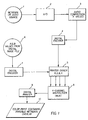
- Fig. 1 is a schematic diagram showing how a source of metadata, such as an audio signal, is converted to a digital signal, encoded, passed to a 4-color film/paper writer in combination with the R,G,B values from a pictorial image file, multiplexed, then printed as an invisible image onto a color photograph.
- a source of metadata such as an audio signal
- Fig. 2 is a schematic diagram of a hand held reader and its elements within that sense the invisible metadata image in the picture, reads the signal, decodes the information, and then reproduces it as sound through a speaker.
- the invention provides a system for incorporating metadata in a photographic element.
- the invention provides a photographic system, including a 4-channel digital film writer, a false sensitized photographic element capable of being digitally exposed and which provides a 4 th sensitized layer to record invisible metadata information, such as sound, a hand-held metadata reader which senses the invisible metadata image in the element, decodes the metadata information, and reproduces the digital signal as sound or other information.
- invisible metadata information such as sound
- a hand-held metadata reader which senses the invisible metadata image in the element, decodes the metadata information, and reproduces the digital signal as sound or other information.
- Metadata refers to any information separate and apart from the actual image of the picture seen by the end user.
- metadata may be text, numbers, or other coded information, including audio, binary, digital or graphic information which, when encoded and included with the image, adds information to the image without adding to or subtracting from image content.
- Metadata in general, may be visible or invisible. In this application, the metadata information is spatially coincident with the image information, it is preferred to be invisible, either by its lack of color or by its image size (i.e., too small to see). Examples of metadata are the UPC codes currently used to encode the price and other information about wholesale or food goods, product code numbers used to track inventory, e-stamps used for digital postage, etc.
- metadata may include the date of film printing and processing, information regarding the type of film negative, the color correction codes used in printing, the name of the photofinisher, etc.
- the schematic diagram in Fig. 1 depicts the collection, encoding, and writing of the metadata and image information onto a four-color false sensitized color photograph.
- the metadata, or sound file (1) such as that captured and stored by many digital film cameras today, is first digitized (2) (if necessary). Since a 10-second sound bite may convert to a digital file of perhaps 400 k-bytes or larger, it is desirable to compress the file to a smaller size.
- Many software algorithms are available that accomplish audio compression (3), such as that from Digital Voice Systems, Inc., AMBE-1000 Voice Coder.
- the data file may be further encoded (4) for printing in a digital file format known as "Paper Disk”.
- This encoding software is available from Cobblestone Software, Inc., in Lexington, Mass.
- Fig. 1 On a parallel path, as shown in Fig. 1, is the image information from the original pictorial scene, which may have been captured on film or in a digital camera. If the original image was made on film, the image must first be scanned in a film or paper scanner to record the R,G,B values as a function of pixel position in the image. This process creates a spatial array of R,G,B values proportional to the amounts of red, green, and blue light in the original scene and stores them as a function of pixel position (6).
- a common digital picture storage file format is called JPEG (jpg).
- This digital image file is then read and re-encoded (7) in a format compatible with the digital printer.
- This information is subsequently transmitted to the printer driver engine (5) where it is combined with the encoded metadata sound file then the 4-channel R,G,B,X file, where the X-channel represents the metadata channel, is read and the code values are sent to the 4-channel multiplexer (8) of the digital printer.
- the multiplexer (8) drives the 4-color digital printer (9).
- This printer contains the four light sources that have been matched to the spectral sensitivities of the output writing media (10), a color paper, for example.
- the printer is driven to scan pixel by pixel across the media, and the four different light sources are modulated in proportion the different amounts of light necessary to expose the R,G,B pictorial image and the X-metadata image. In principle, this process could be accomplished in two separate steps. The first in writing the pictorial information and the second writing the metadata information, but in practice, it is more efficient to have the signals combined and write all four simultaneously.
- Illuminant sources There are numerous commercially available digital printers in the market place. Their design generally is based upon the type of illuminant source chosen to expose the media. Illuminant sources have generally fallen into four categories: Lasers, laser diodes, light emitting diodes (LED's), or cathode ray tubes (CRT's). LED's as the choice of light source are commercially available over a wide range of wavelengths, are compact, and their power output is stable and easy to regulate. A representative sampling of LED's is given below: Manufacturer Type/Model Output Wavelength Siemens Corp. GaN, LB5416 430 nm Nichia Chemical Industries Ltd. GaN, NSPB-WR 470 nm Nichia Chemical Industries Ltd.
- the digital printer light sources are preferably unique sources and different in their spectral output by approximately 50 nm. It is also useful to have the printer sources be narrowly collimated so that the output wavelengths are singularly unique and as closely matched to the spectral sensitivities of the four-color paper as possible.
- the printer electronics drive the location of the exposing bean of mixed, modulated light across the media. This is frequently accomplished by exposing the beam onto a rapidly rotating polygon whose facets are aligned with the media.
- Preferred light sources are lasers, laser diodes, and LED's due to their narrow output bandwidth and their ability to be modulated at high frequency. Combinations of different types of light sources are also acceptable.
- the system comprises the photographic element containing an additional imaging layer, other than the R, G, B layers already present in all color systems.
- This layer can be exposed with light of some pre-determined wavelength in a digital printer whose wavelength corresponds to the spectral sensitivity of the emulsion that is coated within said 4 th sensitized layer.
- the spectral sensitivity of this layer is unique compared to the spectral sensitivities of the imaging layers so that when the exposure is made onto the element which will record the metadata, the layers containing the imaging chemistry to produce the pictorial image are not in any way exposed or compromised.
- an additional 4 th exposure is made which contains the metadata information.
- the pictorial portion of the photographic element has spectral sensitivities in the blue region at about 473nm, in the green region at about 550 nm and in the red region at about 695 nm
- the 4 th sensitized layer could be designed to be exposed at one any of several locations.
- One opportunity is to place the spectral sensitization in the near infrared region, or somewhat past 700 nm, more preferably past 750 nm so as not to confuse the response of this layer with the red sensitive layer.
- Digital exposing devices are readily available at a variety of wavelengths that have sufficient power output and a narrow wavelength of power distribution to meet this requirement.
- a typical multicolor photographic element comprises a support bearing a cyan dye image forming layer comprised of at least one red light sensitive silver halide emulsion having associated therewith at least one cyan dye-forming coupler, a magenta dye image forming layer comprising at least one green light sensitive silver halide emulsion having associated therewith at least one magenta dye-forming coupler, and a yellow dye image forming layer comprising at least one blue-sensitive silver halide emulsion having associated therewith at least one yellow dye-forming coupler.
- the element can contain additional layers, such as filter layers, interlayers, overcoat layers, subbing layers, and the like.
- the silver halide emulsions employed in these photographic elements can be either negative-working or positive-working. Suitable emulsions and their preparation as well as methods of chemical and spectral sensitization are described in Sections I, and III-IV. Vehicles and vehicle related addenda are described in Section II. Dye image formers and modifiers are described in Section X. Various additives such as UV dyes, brighteners, luminescent dyes, antifoggants, stabilizers, light absorbing and scattering materials, coating aids, plasticizers, lubricants, antistats and matting agents are described, for example, in Sections VI-IX. Layers and layer arrangements, color negative and color positive features, scan facilitating features, supports, exposure and processing can be found in Sections XI-XX.
- any photographic coupler known to the art can be used in conjunction with elements of the invention. Suitable couplers are described in Research Disclosure, Item 36544, Section X. In addition, the structures of particularly preferred couplers can be found in an article entitled "Typical and Preferred Color Paper, Color Negative, and Color Reversal Photographic Elements and Processing" which was published in Research Disclosure, February 1995, Volume 370, Section II.
- cyan dye forming coupler of the invention is one having Formula (I): wherein
- Coupler (I) is a 2,5-diacylaminophenol cyan coupler in which the 5-acylamino moiety is an amide of a carboxylic acid which is substituted in the alpha position by a particular sulfone (-SO 2 -) group.
- the sulfone moiety must be an arylsulfone and cannot be an alkylsulfone, and must be substituted only at the meta or para position of the aryl ring.
- the 2-acylamino moiety must be an amide (-NHCO-) of a carboxylic acid, and cannot be a ureido (-NHCONH-) group.
- R 1 represents hydrogen or an alkyl group including linear or branched cyclic or acyclic alkyl group of 1 to 10 carbon atoms, suitably a methyl, ethyl, n-propyl, isopropyl or butyl group, and most suitably an ethyl group.
- R 2 represents an aryl group or an alkyl group such as a perfluoroalkyl group.
- alkyl groups typically have 1 to 20 carbon atoms, usually 1 to 4 carbon atoms, and include groups such as methyl, propyl and dodecyl,; a perfluoroalkyl group having 1 to 20 carbon atoms, typically 3 to 8 carbon atoms, such as trifluoromethyl or perfluorotetradecyl, heptafluoropropyl or heptadecylfluorooctyl; a substituted or unsubstituted aryl group typically having 6 to 30 carbon atoms, which may be substituted by, for example, 1 to 4 halogen atoms, a cyano group, a carbonyl group, a carbonamido group, a sulfonamido group, a carboxy group, a sulfo group, an alkyl group, an aryl group, an alkoxy
- R 2 represents a heptafluoropropyl group, a 4-chlorophenyl group, a 3,4-dichlorophenyl group, a 4-cyanophenyl group, a 3-chloro-4-cyanophenyl group, a pentafluorophenyl group, a 4-carbonamidophenyl group, a 4-sulfonamidophenyl group, or an alkylsulfonylphenyl group.
- each X is located at the meta or para position of the phenyl ring, and each independently represents a linear or branched, saturated or unsaturated alkyl or alkenyl group such as methyl, t-butyl, dodecyl, pentadecyl or octadecyl; an alkoxy group such as methoxy, t-butoxy or tetradecyloxy; an aryloxy group such as phenoxy, 4-t-butylphenoxy or 4-dodecylphenoxy; an alkyl or aryl acyloxy group such as acetoxy or dodecanoyloxy; an alkyl or aryl acylamino group such as acetamido, benzamido, or hexadecanamido; an alkyl or aryl sulfonyloxy group such as methylsulfonyloxy, dodecylsulfonyloxy, or
- X represents the above groups having 1 to 30 carbon atoms, more preferably 8 to 20 linear carbon atoms. Most typically, X represents a linear alkyl group of 12 to 18 carbon atoms such as dodecyl, pentadecyl or octadecyl.
- n represents 1, 2, or 3; if n is 2 or 3, then the substituents X may be the same or different.
- Z represents a hydrogen atom or a group which can be split off by the reaction of the coupler with an oxidized color developing agent, known in the photographic art as a "coupling-off group".
- the presence or absence of such groups determines the chemical equivalency of the coupler, i.e., whether it is a 2-equivalent or 4-equivalent coupler, and its particular identity can modify the reactivity of the coupler.
- Such groups can advantageously affect the layer in which the coupler is coated, or other layers in the photographic recording material, by performing, after release from the coupler, functions such as dye formation, dye hue adjustment, development acceleration or inhibition, bleach acceleration or inhibition, electron transfer facilitation, color correction, and the like.
- coupling-off groups include, for example, halogen, alkoxy, aryloxy, heterocyclyloxy, sulfonyloxy, acyloxy, acyl, heterocyclyl, sulfonamido, heterocyclylthio, benzothiazolyl, phosophonyloxy, alkylthio, arylthio, and arylazo.
- These coupling-off groups are described in the art, for example, in U.S. Patent Nos. 2,455,169; 3,227,551; 3,432,521; 3,467,563; 3,617,291; 3,880,661; 4,052,212; and 4,134,766; and in U.K. Patent Nos. and published applications 1,466,728; 1,531,927; 1,533,039; 2,066,755A; and 2,017,704A. Halogen, alkoxy and aryloxy groups are most suitable.
- the coupling-off group is a chlorine atom.
- the substituent groups R 1 , R 2 , X, and Z be selected so as to adequately ballast the coupler and the resulting dye in the organic solvent in which the coupler is dispersed.
- the ballasting may be accomplished by providing hydrophobic substituent groups in one or more of the substituent groups R 1 , R 2 , X, and Z.
- a ballast group is an organic radical of such size and configuration as to confer on the coupler molecule sufficient bulk and aqueous insolubility as to render the coupler substantially nondiffusible from the layer in which it is coated in a photographic element.
- substituent groups R 1 , R 2 , X, and Z in formula (I) are suitably chosen to meet these criteria.
- the ballast must contain at least 8 carbon atoms and typically contains 10 to 30 carbon atoms. Suitable ballasting may also be accomplished by providing a plurality of groups which in combination meet these criteria.
- R 1 in formula (I) is a small alkyl group. Therefore, in these embodiments the ballast would be primarily located as part of groups R 2 , X, and Z.
- the coupling-off group Z contains a ballast, it is often necessary to ballast the other substituents as well, since Z is eliminated from the molecule upon coupling; thus, the ballast is most advantageously provided as part of groups R 2 and X.
- Preferred magenta couplers are 1H-pyrazolo [5,1-c]-1,2,4-triazole and 1H-pyrazolo [1,5-b]-1,2,4-triazole.
- Examples of 1H-pyrazolo [5,1-c]-1,2,4-triazole couplers are described in U.K. Patent Nos. 1,247,493; 1,252,418; 1,398,979; U.S. Patent Nos. 4,443,536; 4,514,490; 4,540,654; 4,590,153; 4,665,015; 4,822,730; 4,945,034; 5,017,465; and 5,023,170.
- 1H-pyrazolo [1,5-b]-1,2,4-triazoles can be found in European Patent applications 176,804; 177,765; U.S Patent Nos. 4,659,652; 5,066,575; and 5,250,400.
- pyrazoloazole magenta couplers of general structures PZ-1 and PZ-2 are especially preferred: wherein R a , R b , and X are as defined for MAGENTA-1.
- magenta couplers PZ-1 and PZ-2 wherein X is not equal to a hydrogen. This is the case because of the advantageous drop in silver required to reach the desired density in the print element.
- Typical magenta couplers that may be used in the inventive photographic element are shown below.
- the most preferred magenta coupler is
- Couplers that form yellow dyes upon reaction with oxidized color developing agent and which are useful in elements of the invention are described in such representative patents and publications as: U.S. Patent Nos. 2,875,057; 2,407,210; 3,265,506; 2,298,443; 3,048,194; 3,447,928 and "Farbkuppler - Eine Literature Ubersicht,” published in Agfa Mitannonen, Band III, pp. 112-126 (1961).
- Such couplers are typically open chain ketomethylene compounds.
- yellow couplers such as described in, for example, European Patent Application Nos. 482,552; 510,535; 524,540; 543,367; and U.S. Patent No. 5,238,803.
- Typical preferred yellow couplers are represented by the following formulas: wherein R 1 , R 2 , R 3 , R 4 , Q 1 and Q 2 each represents a substituent; X is hydrogen or a coupling-off group; Y represents an aryl group or a heterocyclic group; Q3 represents an organic residue required to form a nitrogen-containing heterocyclic group together with the >N ⁇ ; and Q 4 represents nonmetallic atoms necessary to from a 3- to 5-membered hydrocarbon ring or a 3- to 5-membered heterocyclic ring which contains at least one hetero atom selected from N, O, S, and P in the ring.
- Q 1 and Q 2 each represents an alkyl group, an aryl group, or a heterocyclic group, and R 2 represents an aryl or tertiary alkyl group.
- Preferred yellow couplers for use in elements of the invention are represented by YELLOW-4, wherein R 2 represents a tertiary alkyl group, Y represents an aryl group, and X represents an aryloxy or N-heterocyclic coupling-off group.
- the most preferred yellow couplers are represented by YELLOW-5, wherein R 2 represents a tertiary alkyl group, R 3 represents a halogen or an alkoxy substituent, R 4 represents a substituent and X represents a N-heterocyclic coupling-off group because of their good development and desirable color.
- yellow couplers are represented by YELLOW-5, wherein R 2 , R 3 and R 4 are as defined above, and X is represented by the following formula: wherein Z is oxygen of nitrogen and R 5 and R 6 are substituents. Most preferred are yellow couplers wherein Z is oxygen and R 5 and R 6 are alkyl groups.
- Typical yellow couplers that may be used in the inventive photographic element are shown below.
- ballast groups include substituted or unsubstituted alkyl or aryl groups containing 8 to 40 carbon atoms.
- substituents on such groups include alkyl, aryl, alkoxy, aryloxy, alkylthio, hydroxy, halogen, alkoxycarbonyl, aryloxcarbonyl, carboxy, acyl, acyloxy, amino, anilino, carbonamido (also known as acylamino), carbamoyl, alkylsulfonyl, arylsulfonyl, sulfonamido, and sulfamoyl groups wherein the substituents typically contain 1 to 40 carbon atoms. Such substituents can also be further substituted. Alternatively, the molecule can be made immobile by attachment to polymeric backbone.
- Polymer containing dispersions used in the elements of the invention may be prepared by emulsifying a mixed oil solution comprising polymer and the photographically useful compounds desired in the dispersion, as described in U.S. Patents 3,619,195 and 4,857,449.
- Polymer-containing dispersions used in the elements of the invention may also be prepared as loaded latex dispersions. These may be prepared according to at least three types of process.
- the first process described in, for example, U.S. Patent 4,203,716, involves dissolving the hydrophobic photographically useful compounds to be loaded in a volatile or water miscible auxiliary solvent, combining this solution with an aqueous solution containing a polymer latex, and diluting the dispersion with additional aqueous solution or evaporating the auxiliary solvent to cause loading to occur.
- a second, more preferred method for preparing loaded latex formulations is to subject an oil solution or an aqueous dispersion of an oil solution comprising photographically useful compounds, to conditions of high shear or turbulence, in the presence of a polymer latex, with sufficient shear to cause loading as described in U.S. Patent 5,594,047.
- a third possible way to prepare some loaded latex formulations is to simply combine a polymer latex with a dispersed oil solution, such that the oil solution and latex are miscible, in the presence of surfactant, for a sufficient time before the dispersion is coated for loading to occur as described in U.S. Patent 5,558,980.
- Polymers used in the invention are preferably water-insoluble, and sufficiently hydrophobic to be incorporated as components of the hydrophobic dispersed phase of the dispersions used in the elements of the invention.
- the polymers may be prepared by bulk polymerization or solution polymerization processes. Especially preferred among possible polymerization processes is the free-radical polymerization of vinyl monomers in solution.
- Preferred latex polymers of the invention include addition polymers prepared by emulsion polymerization. Especially preferred are polymers prepared as latex with essentially no water-miscible or volatile solvent added to the monomer. Also suitable are dispersed addition or condensation polymers, prepared by emulsification of a polymer solution, or self-dispersing polymers.
- Especially preferred latex polymers include those prepared by free-radical polymerization of vinyl monomers in aqueous emulsion. Polymers comprising monomers which form water-insoluble homopolymers are preferred, as are copolymers of such monomers, which may also comprise monomers which give water-soluble homopolymers, if the overall polymer composition is sufficiently water-insoluble to form a latex.
- Suitable monomers include allyl compounds such as allyl esters (e.g., allyl acetate, allyl caproate, etc.); vinyl ethers (e.g., methyl vinyl ether, butyl vinyl ether, methoxyethyl vinyl ether, ethoxyethyl vinyl ether, chloroethyl vinyl ether, 1-methyl-2,2-dimethylpropyl vinyl ether, hydroxyethyl vinyl ether, diethylene glycol vinyl ether, dimethylaminoethyl vinyl ether, butylaminoethyl vinyl ether, benzyl vinyl ether, tetrahydrofurfuryl vinyl ether, etc.); vinyl esters (such as vinyl acetate, vinyl propionate, vinyl butyrate, vinyl isobutyrate, vinyl dimethyl propionate, vinyl ethyl butyrate, vinyl chloroacetate, vinyl dichloroacetate, vinyl methoxyacetate, vinyl phenyl acetate, vinyl
- Suitable free-radical initiators for the polymerization include, but are not limited to, the following compounds and classes.
- Inorganic salts suitable as initiators include potassium persulfate, sodium persulfate, potassium persulfate with sodium sulfite, etc.
- Peroxy compounds which may be used include benzoyl peroxide, t-butyl hydroperoxide, cumyl hydroperoxide, etc.
- Azo compounds which may be used include azobis(cyanovaleric acid), azobis-(isobutyronitrile), 2,2'-azobis(2-amidinopropane) dihydrochloride, etc.
- the support utilized in the photographic elements of the invention may be any suitable material. Suitable materials include paper, resin coated paper, transparent and opaque plastic sheets. The preferred sheets are about 7 mils thickness.
- the ultraviolet material is more effective if placed more toward the surface of the photographic element. It is preferred that it be placed above the blue light sensitive layer rather than in lower interlayers.
- any reference to a substituent by the identification of a group containing a substitutable hydrogen e.g. alkyl, amine, aryl, alkoxy, heterocyclic, etc.
- a substitutable hydrogen e.g. alkyl, amine, aryl, alkoxy, heterocyclic, etc.
- substituents include alkyl, aryl, anilino, carbonamido, sulfonamido, alkylthio, arylthio, alkenyl, cycloalkyl, and further to these exemplified are halogen, cycloalkenyl, alkinyl, heterocyclyl, sulfonyl, sulfinyl, phosphonyl, acyl, carbamoyl, sulfamoyl, cyano, alkoxy, aryloxy, heterocyclyloxy, siloxy, acyloxy, carbamoyloxy, amino, alkylamino, imido, ureido, sulfamoylamino, alkoxycarbonylamino, aryloxycarbonylamino, alkoxycarbonyl, aryloxycarbonyl, heterocyclylthio, spiro compound residues, and bridged hydrocarbon compound residues.
- an interlayer containing an anticolor-mixing agent is preferred.
- these scavengers are ballasted to keep them in the layer in which they were coated.
- the scavengers work by reducing any excess oxidized developer back to the developer form.
- Anticolor-mixing agents include compounds such as derivatives of hydroquinones (e.g. see U.S. Patent Nos. 2,336,327; 2,360,290; 2,403,721; 2,701,197; 2,728,659; and 3,700,453) aminophenols, amines, gallic acid, catechol, ascorbic acid, hydrazides (e.g. U.S. 4,923,787), sulfonamidophenols (e.g. U.S. 4,447,523), and non color-forming couplers.
- hydroquinones e.g. see U.S. Patent Nos. 2,336,327; 2,360,290; 2,403,721; 2,701,197; 2,728,659; and 3,
- the photographic element may contain epoxy solvents (EP 164,961); ballasted chelating agents such as those in U.S. 4,994,359 to reduce sensitivity to polyvalent cations such as calcium; and stain reducing compounds such as described in U.S. Patent Nos. 5,068,171; 5,096,805; and 5,126,234.
- the particular base material utilized may be any material conventionally used in silver halide color papers. Such materials are disclosed in Research Disclosure, September 1994, Item 36544, Section XV. It may be desired to coat the photographic element on pH adjusted support as described in U.S. 4,917,994. If desired, false sensitization, as described in Hahm in U.S. 4,902,609, can be used to provide added detail in color paper embodiments.
- emulsions can be sensitized with mixtures of two or more sensitizing dyes which form mixed dye aggregates on the surface of the emulsion grain.
- the use of mixed dye aggregates enables adjustment of the spectral sensitivity of the emulsion to any wavelength between the extremes of the wavelengths of peak sensitivities ( ⁇ -max) of the two or more dyes. This practice is especially valuable if the two or more sensitizing dyes absorb in similar portions of the spectrum (i.e., blue, or green or red and not green plus red or blue plus red or green plus blue). Since the function of the spectral sensitizing dye is to modulate the information recorded in the negative which is recorded as an image dye, positioning the peak spectral sensitivity at or near the ⁇ -max of the image dye in the color negative produces the optimum preferred response.
- emulsions of this invention may contain a mixture of spectral sensitizing dyes which are substantially different in their light absorptive properties.
- Hahm in U.S. 4,902,609 describes a method for broadening the effective exposure latitude of a color negative paper by adding a smaller amount of green spectral sensitizing dye to a silver halide emulsion having predominately a red spectral sensitivity.
- red sensitized emulsion when it is exposed to green light, it has little, if any, response.
- a proportionate amount of cyan image dye will be formed in addition to the magenta image dye, causing it to appear to have additional contrast and, hence, a broader exposure latitude.
- Waki et al in U.S. 5,084,374 describes a silver halide color photographic material in which the red spectrally sensitized layer and the green spectrally sensitized layers are both sensitized to blue light. Like Hahm, the second sensitizer is added in a smaller amount to the primary sensitizer. When these imaging layers are given a large enough exposure of the blue light exposure, they produce yellow image dye to complement the primary exposure. This process of adding a second spectral sensitizing dye of different primary absorption is called false-sensitization.
- Any silver halide combination can be used, such as silver chloride, silver chlorobromide, silver chlorobromoiodide, silver bromide, silver bromoiodide, or silver chloroiodide. Due to the need for rapid processing of the color paper, silver chloride emulsions are preferred. In some instances, silver chloride emulsions containing small amounts of bromide, or iodide, or bromide and iodide are preferred, generally less than 2.0 mole percent of bromide less than 1.0 mole percent of iodide.
- Bromide or iodide addition when forming the emulsion may come from a soluble halide source such as potassium iodide or sodium bromide or an organic bromide or iodide or an inorganic insoluble halide such as silver bromide or silver iodide.
- a soluble halide source such as potassium iodide or sodium bromide or an organic bromide or iodide or an inorganic insoluble halide such as silver bromide or silver iodide.
- the shape of the silver halide emulsion grain can be cubic, pseudo-cubic, octahedral, tetradecahedral or tabular. It is preferred that the 3-dimensional grains be monodisperse and that the grain size coefficient of variation of the 3-dimensional grains is less than 35% or, most preferably less than 25%.
- the emulsions may be precipitated in any suitable environment such as a ripening environment, or a reducing environment. Specific references relating to the preparation of emulsions of differing halide ratios and morphologies are Evans U.S. Patent 3,618,622; Atwell U.S. Patent 4,269,927; Wey U.S. Patent 4,414,306; Maskasky U.S.
- Patent 4,400,463 Maskasky U.S. Patent 4,713,323; Tufano et al U.S. Patent 4,804,621; Takada et al U.S. Patent 4,738,398; Nishikawa et al U.S. Patent 4,952,491; Ishiguro et al U.S. Patent 4,493,508; Hasebe et al U.S. Patent 4,820,624; Maskasky U.S. Patent 5,264,337; and House et al EP 534,395.
- the combination of similarly spectrally sensitized emulsions can be in one or more layers, but the combination of emulsions having the same spectral sensitivity should be such that the resultant D vs. log-E curve and its corresponding instantaneous contrast curve should be such that the instantaneous contrast of the combination of similarly spectrally sensitized emulsions generally increases as a function of exposure.
- Emulsion precipitation is conducted in the presence of silver ions, halide ions and in an aqueous dispersing medium including, at least during grain growth, a peptizer. Grain structure and properties can be selected by control of precipitation temperatures, pH and the relative proportions of silver and halide ions in the dispersing medium. To avoid fog, precipitation is customarily conducted on the halide side of the equivalence point (the point at which silver and halide ion activities are equal). Manipulations of these basic parameters are illustrated by the citations including emulsion precipitation descriptions and are further illustrated by Matsuzaka et al U.S. Patent 4,497,895; Yagi et al U.S.
- Patent 4,728,603 Sugimoto U.S. Patent 4,755,456; Kishita et al U.S. Patent 4,847,190; Joly et al U.S. Patent 5,017,468; Wu U.S. Patent 5,166,045; Shibayama et al EPO 0 328 042; and Kawai EPO 0 531 799.
- Reducing agents present in the dispersing medium during precipitation can be employed to increase the sensitivity of the grains, as illustrated by Takada et al U.S. Patent 5,061,614; Takada U.S. Patent 5,079,138; and EPO 0 434 012, Inoue U.S. Patent 5,185,241; Yamashita et al EPO 0 369 491; Ohashi et al EPO 0 371 338; Katsumi EPO 435 270 and 0 435 355; and Shibayama EPO 0 438 791.
- Chemically sensitized core grains can serve as hosts for the precipitation of shells, as illustrated by Porter et al U.S. Patents 3,206,313 and 3,327,322; Evans U.S. Patent 3,761,276; Atwell et al U.S. Patent 4,035,185; and Evans et al U.S. Patent 4,504,570.
- Periods 3-7 ions including Group VIII metal ions (Fe, Co, Ni and platinum metals (pm) Ru, Rh, Pd, Re, Os, Ir and Pt), Mg, Al, Ca, Sc, Ti, V, Cr, Mn, Cu Zn, Ga, As, Se, Sr, Y, Mo, Zr, Nb, Cd, In, Sn, Sb, Ba, La, W, Au, Hg, Tl, Pb, Bi, Ce and U can be introduced during precipitation.
- Group VIII metal ions Fe, Co, Ni and platinum metals (pm) Ru, Rh, Pd, Re, Os, Ir and Pt
- Mg Al, Ca, Sc, Ti, V, Cr, Mn, Cu Zn, Ga, As, Se, Sr, Y, Mo, Zr, Nb, Cd, In, Sn, Sb, Ba, La, W, Au, Hg, Tl, Pb, Bi, Ce and U can be introduced during precipitation.
- the dopants can be employed (a) to increase the sensitivity of either (al) direct positive or (a2) negative working emulsions, (b) to reduce (b1) high or (b2) low intensity reciprocity failure, (c) to (c1) increase, (c2) decrease or (c3) reduce the variation of contrast, (d) to reduce pressure sensitivity, (e) to decrease dye desensitization, (f) to increase stability, (g) to reduce minimum density, (h) to increase maximum density, (i) to improve room light handling and (j) to enhance latent image formation in response to shorter wavelength (e.g. X-ray or gamma radiation) exposures.
- any polyvalent metal ion (pvmi) is effective.
- the selection of the host grain and the dopant can be varied to achieve aim photographic properties, as illustrated by B.H. Carroll, "Iridium Sensitization: A Literature Review", Photographic Science and Engineering, Vol. 24, No. 6 Nov./Dec. 1980, pp. 265-267 (pm, Ir, a, b and d); Hochstetter U.S. Patent 1,951,933 (Cu); De Witt U.S. Patent 2,628,167 (Tl, a, c); Mueller et al U.S. Patent 2,950,972 (Cd, j); Spence et al U.S.
- Patent 3,687,676 and Gilman et al U.S. Patent 3,761,267 (Pb, Sb, Bi, As, Au, Os, Ir, a); Ohkubu et al U.S. Patent 3,890,154 (VIII, a); Iwaosa et al U.S. Patent 3,901,711 (Cd, Zn, Co, Ni, Tl, U, Th, Ir, Sr, Pb, bl); Habu et al U.S. Patent 4,173,483 (VIII, bl); Atwell U.S. Patent 4,269,927 (Cd, Pb, Cu, Zn, a2); Weyde U.S.
- Patent 4,413,055 Cu, Co, Ce, a2); Akimura et al U.S. Patent 4,452,882 (Rh, i); Menjo et al U.S. Patent 4,477,561 (pm, f); Habu et al U.S. Patent 4,581,327 (Rh, cl, f); Kobuta et al U.S. Patent 4,643,965 (VIII, Cd, Pb, f, c2); Yamashita et al U.S. Patent 4,806,462 (pvmi, a2, g); Grzeskowiak et al U.S.
- Patent 4,4,828,962 (Ru+Ir, bl); Janusonis U.S. Patent 4,835,093 (Re, al); Leubner et al U.S. Patent 4,902,611 (Ir+4); Inoue et al U.S. Patent 4,981,780 (Mn, Cu, Zn, Cd, Pb, Bi, In, Tl, Zr, La, Cr, Re, VIII, cl, g, h); Kim U.S. Patent 4,997,751 (Ir, b2); Kuno U.S. Patent 5,057,402 (Fe, b, f); Maekawa et al U.S.
- Patent 5,134,060 (Ir, b, c3); Kawai et al U.S. Patent 5,164,292 (Ir+Se, b); Asami U.S. Patents 5,166,044 and 5,204,234 (Fe+Ir, a2 b, cl, c3); Wu U.S. Patent 5,166,045 (Se, a2); Yoshida et al U.S. Patent 5,229,263 (Ir+Fe/Re/Ru/Os, a2, b1); Marchetti et al U.S.
- Patents 5,264,336 and 5,268,264 (Fe, g); Komarita et al EPO 0 244 184 (Ir, Cd, Pb, Cu, Zn, Rh, Pd, Pt, Tl, Fe, d); Miyoshi et al EPO 0 488 737 and 0 488 601 (Ir+VIII/Sc/Ti/V/Cr/Mn/Y/Zr/Nb/Mo/La/Ta/W/Re, a2, b, g); Ihama et al EPO 0 368 304 (Pd, a2, g); Tashiro EPO 0 405 938 (Ir, a2, b); Murakami et al EPO 0 509 674 (VIII, Cr, Zn, Mo, Cd, W, Re, Au, a2, b, g) and Budz WO 93/02390 (Au, g); Ohkubo et
- coordination ligands such as halo, aquo, cyano, cyanate, fulminate, thiocyanate, selenocyanate, nitrosyl, thionitrosyl, oxo, carbonyl and ethylenediamine tetraacetic acid (EDTA) ligands have been disclosed and, in some instances, observed to modify emulsion properties, as illustrated by Grzeskowiak U.S.
- Oligomeric coordination complexes can also be employed to modify grain properties, as illustrated by Evans et al U.S. Patent 5,024,931.
- Dopants can be added in conjunction with addenda, antifoggants, dye, and stabilizers either during precipitation of the grains or post precipitation, possibly with halide ion addition. These methods may result in dopant deposits near or in a slightly subsurface fashion, possibly with modified emulsion effects, as illustrated by Ihama et al U.S. Patent 4,693,965 (Ir, a2); Shiba et al U.S. Patent 3,790,390 (Group VIII, a2, b1); Habu et al U.S.
- Patent 4,147,542 Group VIII, a2, b1; Hasebe et al EPO 0 273 430 (Ir, Rh, Pt); Ohshima et al EPO 0 312 999 (Ir, f); and Ogawa U.S. Statutory Invention Registration H760 (Ir, Au, Hg, T1, Cu, Pb, Pt, Pd, Rh, b, f).
- Desensitizing or contrast increasing ions or complexes are typically dopants which function to trap photogenerated holes or electrons by introducing additional energy levels deep within the bandgap of the host material.
- Examples include, but are not limited to, simple salts and complexes of Groups 8-10 transition metals (e.g., rhodium, iridium, cobalt, ruthenium, and osmium), and transition metal complexes containing nitrosyl or thionitrosyl ligands as described by McDugle et al U.S. Patent 4,933,272.
- K 3 RhCl 6 (NH 4 ) 2 Rh(Cl 5 )H 2 O, K 2 IrCl 6 , K 3 IrCl 6 , K 2 IrBr 6 , K 2 IrBr 6 , K 2 RuCl 6 , K 2 Ru(NO)Br 5 , K 2 Ru(NS)Br 5 , K 2 OsCl 6 , Cs 2 Os(NO)Cl 5 , and K 2 Os(NS)Cl 5 .
- Amine, oxalate, and organic ligand complexes of these or other metals as disclosed in Olm et al U.S. Patent 5,360,712 are also specifically contemplated.
- Shallow electron trapping ions or complexes are dopants which introduce additional net positive charge on a lattice site of the host grain, and which also fail to introduce an additional empty or partially occupied energy level deep within the bandgap of the host grain.
- substitution into the host grain involves omission from the crystal structure of a silver ion and six adjacent halide ions (collectively referred to as the seven vacancy ions).
- the seven vacancy ions exhibit a net charge of -5.
- a six coordinate dopant complex with a net charge more positive than -5 will introduce a net positive charge onto the local lattice site and can function as a shallow electron trap.
- the presence of additional positive charge acts as a scattering center through the Coulomb force, thereby altering the kinetics of latent image formation.
- metal ions or complexes Based on electronic structure, common shallow electron trapping ions or complexes can be classified as metal ions or complexes which have (i) a filled valence shell or (ii) a low spin, half-filled d shell with no low-lying empty or partially filled orbitals based on the ligand or the metal due to a large crystal field energy provided by the ligands.
- Classic examples of class (i) type dopants are divalent metal complex of Group II, e.g., Mg(2+), Pb(2+), Cd(2+), Zn(2+), Hg(2+), and Tl(3+).
- Some type (ii) dopants include Group VIII complex with strong crystal field ligands such as cyanide and thiocyanate.
- Examples include, but are not limited to, iron complexes illustrated by Ohkubo U.S. Patent 3,672,901; and rhenium, ruthenium, and osmium complexes disclosed by Keevert U.S. Patent 4,945,035; and iridium and platinum complexes disclosed by Ohshima et al U.S. Patent 5,252,456.
- Preferred complexes are ammonium and alkali metal salts of low valent cyanide complexes such as K 4 Fe(CN) 6 , K 4 Ru(CN) 6 , K 4 Os(CN) 6 , K 2 Pt(CN) 4 , and K 3 Ir(CN) 6 .
- K 3 Fe(CN) 6 and K 3 Ru(CN) 6 can also possess shallow electron trapping characteristics, particularly when any partially filled electronic states which might reside within the bandgap of the host grain exhibit limited interaction with photocharge carriers.
- Emulsion addenda that absorb to grain surfaces, such as antifoggants, stabilizers and dyes can also be added to the emulsions during precipitation. Precipitation in the presence of spectral sensitizing dyes is illustrated by Locker U.S. Patent 4,183,756; Locker et al U.S. Patent 4,225,666; Ihama et al U.S. Patents 4,683,193 and 4,828,972; Takagi et al U.S. Patent 4,912,017; Ishiguro et al U.S. Patent 4,983,508; Nakayama et al U.S. Patent 4,996,140; Steiger U.S. Patent 5,077,190; Brugger et al U.S.
- Patent 5,141,845 Metoki et al U.S. Patent 5,153,116; Asami et al EPO 0 287 100 and Tadaaki et al EPO 0 301 508.
- Non-dye addenda are illustrated by Klotzer et al U.S. Patent 4,705,747; Ogi et al U.S. Patent 4,868,35 USC ⁇ 102; Ohya et al U.S. Patent 5,015,563; Brumuller et al U.S. Patent 5,045,444; Maeka et al U.S. Patent 5,070,008; and Vandenabeele et al EPO 0 392 092.
- Chemical sensitization of the materials in this invention is accomplished by any of a variety of known chemical sensitizers.
- the emulsions described herein may or may not have other addenda such as sensitizing dyes, supersensitizers, emulsion ripeners, gelatin, or halide conversion restrainers present before, during, or after the addition of chemical sensitization.
- Sulfur sensitizers may include thiosulfate, thiocyanate or N, N'-carbobothioyl-bis(N-methylglycine).
- Tetrazaindenes such as 4-hydroxy-6-methyl-(1,3,3a,7)-tetrazaindene, are commonly used as stabilizers.
- mercaptotetrazoles such as 1-phenyl-5-mercaptotetrazole or acetamido-1-phenyl-5-mercaptotetrazole.
- Arylthiosulfinates such as tolyl-thiosulfonate or arylsufinates such as tolylthiosulfinate or esters thereof, are also useful.
- ECD is the average equivalent circular diameter of the tabular grains in micrometers and t is the average thickness in micrometers of the tabular grains.
- the average useful ECD of photographic emulsions can range up to about 10 micrometers, although in practice emulsion ECD's seldom exceed about 4 micrometers. Since both photographic speed and granularity increase with increasing ECD's, it is generally preferred to employ the smallest tabular grain ECD's compatible with achieving aim speed requirements.
- Emulsion tabularity increases markedly with reductions in tabular grain thickness. It is generally preferred that aim tabular grain projected areas be satisfied by thin ( t ⁇ 0.2 micrometer) tabular grains. To achieve the lowest levels of granularity it is preferred that aim tabular grain projected areas be satisfied with ultrathin (t ⁇ 0.06 micrometer) tabular grains. Tabular grain thicknesses typically range down to about 0.02 micrometer. However, still lower tabular grain thicknesses are contemplated. For example, Daubendiek et al U.S. Patent 4,672,027 reports a 3 mole percent iodide tabular grain silver bromoiodide emulsion having a grain thickness of 0.017 micrometer. Ultrathin tabular grain high chloride emulsions are disclosed by Maskasky U.S. 5,217,858.
- tabular grains of less than the specified thickness account for at least 50 percent of the total grain projected area of the emulsion.
- tabular grains satisfying the stated thickness criterion account for the highest conveniently attainable percentage of the total grain projected area of the emulsion.
- tabular grains satisfying the stated thickness criteria above account for at least 70 percent of the total grain projected area.
- tabular grains satisfying the thickness criteria above account for at least 90 percent of total grain projected area.
- Suitable tabular grain emulsions can be selected from among a variety of conventional teachings, such as those of the following: Research Disclosure, Item 22534, January 1983, published by Kenneth Mason Publications, Ltd., Emsworth, Hampshire PO10 7DD, England; U.S. Patent Nos.
- the emulsions can be surface-sensitive emulsions, i.e., emulsions that form latent images primarily on the surfaces of the silver halide grains, or the emulsions can form internal latent images predominantly in the interior of the silver halide grains.
- the emulsions can be negative-working emulsions, such as surface-sensitive emulsions or unfogged internal latent image-forming emulsions, or direct-positive emulsions of the unfogged, internal latent image-forming type, which are positive-working when development is conducted with uniform light exposure or in the presence of a nucleating agent.
- Photographic elements can be exposed to actinic radiation, typically in the visible region of the spectrum, to form a latent image and can then be processed to form a visible dye image.
- Processing to form a visible dye image includes the step of contacting the element with a color developing agent to reduce developable silver halide and oxidize the color developing agent. Oxidized color developing agent in turn reacts with the coupler to yield a dye.
- Processing a silver halide color photographic light-sensitive material is basically composed of two steps of 1) color development and 2) desilvering.
- the desilvering stage comprises a bleaching step to change the developed silver back to an ionic-silver state and a fixing step to remove the ionic silver from the light-sensitive material.
- the bleaching and fixing steps can be combined into a monobath bleach-fix step that can be used alone or in combination with the bleaching and the fixing step. If necessary, additional processing steps may be added, such as a washing step, a stopping step, a stabilizing step and a pretreatment step to accelerate development.
- the processing chemicals used may be liquids, pastes, or solids, such as powders, tablets, or granules.
- a developer solution in a processor tank can be maintained at a 'steady-state concentration' by the use of another solution that is called the replenisher solution.
- the replenisher solution By metering the replenisher solution into the tank at a rate proportional to the amount of the photographic light-sensitive material being developed, components can be maintained at an equilibrium within a concentration range that will give good performance.
- the replenisher solution is prepared with the component at a concentration higher than the tank concentration. In some cases a material will leave the emulsions layers that will have an effect of restraining development, and will be present at a lower concentration in the replenisher or not present at all.
- a material may be contained in a replenisher in order to remove the influence of a materials that will wash out of the photographic light-sensitive material.
- the buffer, or the concentration of a chelating agent where there may be no consumption the component in the replenisher is the same or similar concentration as in the processor tank.
- the replenisher has a higher pH to account for the acid that is released during development and coupling reactions so that the tank pH can be maintained at an optimum value.
- replenishers are also designed for the secondary bleach, fixer, and stabilizer solutions.
- components are added to compensate for the dilution of the tank which occurs when the previous solution is carried into the tank by the photographic light-sensitive material.
- steps 1) and 2) are preferably applied. Additionally, each of the steps indicated can be used with multistage applications as described in Hahm, U.S. Pat. No. 4,719,173, with cocurrent, counter-current, and contraco arrangements for replenishment and operation of the multistage processor.
- the color developing solution used with this photographic element may contain aromatic primary amine color developing agents, which are well known and widely used in a variety of color photographic processes.
- aromatic primary amine color developing agents which are well known and widely used in a variety of color photographic processes.
- Preferred examples are p -phenylenediamine derivatives. They are usually added to the formulation in a salt form, such as the hydrochloride, sulfate, sulfite, p -toluene-sulfonate, as the salt form is more stable and has a higher aqueous solubility than the free amine.
- the salts listed the p -toluenesulfonate is rather useful from the viewpoint of making a color developing agent highly concentrated. Representative examples are given below, but they are not meant to limit what could be used with the present photographic element:
- any photographic processor known to the art can be used to process the photosensitive materials described herein.
- large volume processors and so-called minilab and microlab processors may be used.
- advantageous would be the use of Low Volume Thin Tank processors as described in the following references: WO 92/10790; WO 92/17819; WO 93/04404; WO 92/17370; WO 91/19226; WO 91/12567; WO 92/07302; WO 93/00612; WO 92/07301; WO 92/09932; U.S. 5,294,956; EP 559,027; U.S. 5,179,404; EP 559,025; U.S. 5,270,762; EP 559,026; U.S. 5,313,243; and U.S. 5,339,131.
- silver halide emulsions with greater than 90 mole % chloride are preferred, and even more preferred are emulsions of greater than 95 mole % chloride.
- silver chloride emulsions containing small amounts of bromide, or iodide, or bromide and iodide are preferred, generally less than 5.0 mole % of bromide less than 2.0 mole % of iodide.
- the inclusion of substantial amounts of bromide and/or iodide would tend to reduce the developability of the emulsion, and thereby reduce the magnitude of the inventive effect.
- the response of the system is predicated upon the ability of the sensor to detect the embedded, invisible code mixed with the pictorial information in the picture.
- the sensor must discriminate the metadata signal from whatever pictorial information is present.
- the invisible information is only invisible to the human eye, but since it is present as an infrared adsorbing dye, the sensor must first distinguish visible light from infrared light. Visible light is generally considered to be light in the 400 nm to 700 nm of the spectrum. The near-infrared region of the spectrum begins at about 700 nm and extends past 900 nm.
- an infrared cutoff filter can be included in the sensor design.
- An example of a filter of this type would be the WR-88A filter, which is commercially available from a variety of suppliers, including the Eastman Kodak Co., and a description of the absorption characteristics as a function of wavelength is also available.
- the sensor detects infrared light reflected from the photograph. To achieve this, the sensor must first illuminate the photograph with infrared light. Therefore, in addition to the sensor having a device which senses infrared light, it must also contain a light source, which produces infrared light and which can be focused onto the photograph.
- a light source which produces infrared light and which can be focused onto the photograph.
- a variety of light sources are available which emit light between 700 nm and 900 nm or beyond. Common tungsten lamps are once such examples, as are quartz-halogen bulbs. The spectral power distributions of the lamps are also widely published.
- the actual infrared detector in the sensor is also commercially available.
- a 1-M pixel CMOS, or CCD array, manufactured by the Eastman Kodak Company is selected. Its spectral response characteristics are known and have been characterized in the 700 nm to 900 nm region.
- the sensor When, in operation, the sensor is pointed at the picture containing the infrared metadata image, and the user triggers the sensor to flash the picture with infrared light. This action triggers the IR-lamp to flash and signals the CMOS or CCD sensor to record the reflected IR light from the image as a 2-dimensional array.
- the loss of intensity of reflected light by the array detector is proportional to the amount of IR dye formed in the 4 th sensitized layer of the photographic element.
- the magnitude of the signal reflected by the image and received by the sensor is the cascaded combination of the illuminance output of the exposing IR light source of the sensor as a function of wavelength, I( ⁇ ), the transmittance filter or combination of filters place in front of the sensor to filter out the visible light and improve image discrimination, F( ⁇ ), the efficiency response of the CMOS or CCD array detector, in arbitrary response units, D( ⁇ ), and the reflectance of the image in the photograph, R i ( ⁇ ).
- the reflectance from the image is the combination of the reflectance of the coated paper base R b ( ⁇ ) plus the reflectance's of the cyan, R C ( ⁇ ), magenta, R M ( ⁇ ), yellow R Y ( ⁇ ) image dyes and the infrared R IR ( ⁇ ), dye.
- R i ( ⁇ ) R b ( ⁇ )+ R C ( ⁇ )+ R M ( ⁇ )+ R Y ( ⁇ )+ R IR ( ⁇ )
- B is the integral, as a function of wavelength, between 700 nm and 900 nm of the product of the intensity of the illuminant, the combination of any cutoff filters in the system, the response of the detector, and the reflectance of the image.
- the combination of image dyes and the infrared dye in the image modulate the brightness of the reflected IR light from the sensor.
- Careful selection of the cutoff filter used in front of the sensor can simplify the image discrimination problem by essentially eliminating all the reflected light below the cutoff of the filter.
- a filter such as a WR88A transmits only 1.1% of light below 720 nm. In essence then, this filter eliminates the brightness contributions of the yellow and magenta image dyes to the signal.
- cyan dyes which are designed to absorb red light (600 to 700 nm) do have an absorption band that tails into the near infrared portion of the spectrum.
- the brightness of the signal is then modulated by the amounts of cyan and infrared image dye in the image. These amounts change as a function of spatial location in the image, as well as image content and metadata content. Since the situation exists where the cyan image dye tails into the infrared and the infrared dye tails into the visible portions of the spectrum, there is a need to co-optimize the cyan and infrared image dyes so that the contributions of the cyan dye to the infrared image and the contribution of the infrared dye to the visible image are minimized.
- the first situation occurs when no cyan image dye is mixed with the infrared dye.
- the modulation of the brightness of the signal from the sensor then is solely due to the changing amount of infrared dye, and when no infrared dye is present, the brightness is maximized.
- the second extreme situation exists when the amount of cyan image dye present in the image is at a maximum amount.
- the cyan image dye rarely exceeds a density of 2.0. In this case, 1% of the incident light is reflected. However, in the near infrared portion of the spectrum, the unwanted absorptions of the cyan dye do not reach this density.
- the overall design of the system requires that the signal to noise ratio be maximized. Since 1 dB is defined as a "just noticeable difference", a difference of 2 dB could be considered as a 'more than significant' difference. To achieve this, the contribution of the cyan dye to the infrared portion of the signal is minimized, the infrared signal is maximized, and the contribution of the infrared dye to the image portion of the picture is minimized.
- the image containing the invisible metadata (10) is first exposed to a flash of infrared light (16) from the metadata sensor (11).
- the infrared light illuminates the image wherein any encoded metadata modulates the light and the non-modulated light is reflected back to the sensor through a lens (12) which focuses the light through a filter (13) or combination of filters and onto a CMOS or CCD detector (14).
- the image sensor electronics (18) that control reading the individual pixels and response characteristics of the detector.
- the output of the image sensor can be temporarily stored in memory (19) before being processed by the metadata image processor (20).
- the metadata image is then decoded (21), decompressed (22), converted to an analogue signal by the D/A converter (23), amplified (24), and subsequently reproduced as an audio file by a speaker (17), incorporated into the sensor.
- the senor be wholly contained and is designed to be a hand-held device, within which is contained the lens (12), filters (13), sensor (14), IR flash lamp (15), image sensor electronics (18), storage memory (19), image processor (20), decoding electronics (21), metadata decompression (22), D/A converter (23), amplifier (24), and speaker (17).
- the unit also contains the necessary power supplies (not depicted) to power the IR flash lamp and related image sensor electronics, as well as the output and speaker power supplies.
- the unit collects the infrared light reflected from the picture image when the user triggers the IR lamp.
- the collected light is focussed through the lens or combination of lenses through the filter or combination of filters.
- the filters pass the IR light and screen out any visible light.
- the light is then imaged onto the CMOS or CCD sensor so that a pixel by pixel image of the photograph is obtained.
- Triggering the IR flash lamp simultaneously triggers the circuitry and electronics of the 2-D sensor to an initial state so that the resultant, captured metadata image can be stored in memory, then processed by the image processor to 'frame', spatially orient, correct for blur and assign code values for the signals of each pixel.
- This encoded information is then passed to the decoder circuit, which interprets the digital signals back into the metadata form where they were originally captured in.
- the signals are subsequently decompressed and expanded to their original size and length, then converted back to their analogue counterparts, amplified and reproduced through an integrated speaker assembly.
- Example 1 Single Layer Coating Containing a Red Sensitized Emulsion
- a silver chloride emulsion was chemically and spectrally sensitized as is described below.
- Red Sensitive Emulsion (Red EM-1): A high chloride silver halide emulsion was precipitated by adding approximately equimolar silver nitrate and sodium chloride solutions into a well-stirred reactor containing gelatin peptizer and thioether ripener. The resultant emulsion contained cubic shaped grains of 0.40 ⁇ m in edge length. In addition, ruthenium hexacyanide dopant (at 16.5 mg/Ag-M) and K 2 IrCl 5 (5-methylthiazole) dopant (at 0.99 mg/Ag-M) were added during the precipitation process.
- This emulsion was optimally sensitized by the addition of a colloidal suspension of aurous sulfide (60 mg/Ag-M) followed by a heat ramp to 65°C for 45 minutes, and further additions of 1-(3-acetamidophenyl)-5-mercaptotetrazole (295 mg/Ag-M), iridium dopant K 2 IrCl 6 (149 ⁇ g/Ag-M), potassium bromide (0.5 Ag-M%), and red sensitizing dye RSD-1 (7.1 mg/Ag-M).
- Dispersions of couplers C-1 to C-5 were emulsified by methods well known to the art, and were coated on the face side of a doubly extruded polyethylene coated color paper support using conventional coating techniques.
- the gelatin layers were hardened with bis (vinylsulfonyl methyl) ether at 2.4 % of the total gelatin.
- the composition of the individual layers is given as follows:
- the emulsion described above was first evaluated in a single emulsion layer-coating format using conventional coating preparation methods and techniques.
- This coating format is described below in detail: Single Layer Coating Format Layer Coating Material Coverage mg/m 2 Overcoat Gelatin 1064. Gel hardener 105. Imaging Emulsion Red EM-1 215.3 Couplers C-1 to C-5 431. Gelatin 1658. Adhesion sub-layer Gelatin 3192. Polyethylene coated paper support
- the respective paper samples were exposed in a Kodak Model 1B sensitometer with a color temperature of 3000° K and filtered with a Kodak WrattenTM 2C plus a Kodak WrattenTM 29 filter and a Hoya HA-50. exposure time was adjusted to 0.1 seconds. The exposures were performed by contacting the paper samples with a neutral density step exposure tablet having an exposure range of 0 to 3 log-E.
- Processing the exposed paper samples is performed with the developer and bleach-fix temperatures adjusted to 35°C. Washing is performed with tap water at 32.2°C.
- the characteristic vector also determined from principle component analysis, was determined using standard characterization methods since the absorption characteristics of a given colorant will vary to some extent with a change in colorant amount. This is due to factors such as measurement flare, colorant-colorant interaction, colorant-support interactions, colorant concentration effects, and the presence of color impurities in the media.
- characteristic vector analysis one can determine a characteristic absorption curve that is representative of the absorption characteristics of the colorant over the complete wavelength and density ranges of interest. This technique is described by J. L. Simonds in the Journal of the Optical Society of America, 53(8), 968-974, 1963.
- the ⁇ -max (normalized to 1.0 density) of the characteristic vector of each dye and the density of each dye vectors were measured at 700 nm and are given in the following table: Sample Coupler ⁇ -max of Dye Vector @ 1.0 Density Density at 700 nm 1 C-1 660 nm 0.73 2 C-2 630 nm 0.33 3 C-3 690 nm 0.99 4 C-4 710 nm 0.99 5 C-5 740 nm 0.83
- Coupler C-3 has an absorption band that falls across both the far-red and near-infrared region.
- Couplers C-4 and C-5 are illustrative of couplers, which form dyes that primarily absorb in the infrared region since their absorption maxima are beyond 700 nm.
- Silver chloride emulsions were chemically and spectrally sensitized as is described below.
- Blue Sensitive Emulsion (Blue EM-2, prepared as described in U.S. 5,252,451, column 8, lines 55-68): A high chloride silver halide emulsion was precipitated by adding approximately equimolar silver nitrate and sodium chloride solutions into a well-stirred reactor containing gelatin peptizer and thioether ripener. Cs 2 Os(NO)Cl 5 (136 ⁇ g/Ag-M) and K 2 IrCl 5 (5-methylthiazole) (72 ⁇ g/Ag-M), dopants were added during the silver halide grain formation for most of the precipitation.
- the resultant emulsion contained cubic shaped grains of 0.60 ⁇ m in edge length.
- This emulsion was optimally sensitized by the addition of a colloidal suspension of aurous sulfide (18.4 mg/Ag-M) and heat ramped up to 60°C during which time blue sensitizing dye BSD-4 , (388 mg/Ag-M), 1-(3-acetamidophenyl)-5-mercaptotetrazole (93 mg/Ag-M) and potassium bromide (0.5 M%) were added.
- blue sensitizing dye BSD-4 (388 mg/Ag-M)
- 1-(3-acetamidophenyl)-5-mercaptotetrazole 93 mg/Ag-M
- potassium bromide 0.5 M%
- Green Sensitive Emulsion (Green EM-1): A high chloride silver halide emulsion was precipitated by adding approximately equimolar silver nitrate and sodium chloride solutions into a well-stirred reactor containing gelatin peptizer and thioether ripener. Cs 2 Os(NO)Cl 5 (1.36 ⁇ g/Ag-M) dopant and K 2 IrCl 5 (5-methylthiazole) (0.54 mg/Ag-M) dopant were added during the silver halide grain formation for most of the precipitation, followed by a shelling without dopant. The resultant emulsion contained cubic shaped grains of 0.30 ⁇ m in edge length.
- This emulsion was optimally sensitized by addition of a colloidal suspension of aurous sulfide (12.3 mg/Ag-M), heat digestion, followed by the addition of silver bromide (0.8 M%), green sensitizing dye, GSD-1 (427 mg/Ag-M), and 1-(3-acetamidophenyl)-5-mercaptotetrazole (96 mg/Ag-M).
- Infrared Sensitive Emulsion (FS EM-1): A high chloride silver halide emulsion was precipitated by adding approximately equimolar silver nitrate and sodium chloride solutions into a well-stirred reactor containing gelatin peptizer and thioether ripener. The resultant emulsion contained cubic shaped grains of 0.40 ⁇ m in edge length.
- ruthenium hexacyanide dopant at 16.5 mg/Ag-M
- K 2 IrCl 5 (5-methylthiazole) dopant (at 0.99 mg/Ag-M) were added during the precipitation process.
- This emulsion was optimally sensitized by the addition of a colloidal suspension of aurous sulfide (60. mg/Ag-M) followed by a heat ramp to 65 °C for 45 minutes, followed by further additions of antifoggant, 1-(3-acetamidophenyl)-5-mercaptotetrazole (295. mg/Ag-M), iridium dopant (K 2 IrCl 6 at 149.
- Infrared Sensitive Emulsion (FS EM-2): A high chloride silver halide emulsion was precipitated by adding approximately equimolar silver nitrate and sodium chloride solutions into a well-stirred reactor containing gelatin peptizer and thioether ripener. The resultant emulsion contained cubic shaped grains of 0.40 ⁇ m in edge length.
- ruthenium hexacyanide dopant at 16.5 mg/Ag-M
- K 2 IrCl 5 (5-methylthiazole) dopant (at 0.99 mg/Ag-M) were added during the precipitation process.
- This emulsion was optimally sensitized by the addition of a colloidal suspension of aurous sulfide (60. mg/Ag-M) followed by a heat ramp to 65 ° C for 45 minutes, followed by further additions of antifoggant, 1-(3-acetamidophenyl)-5-mercaptotetrazole (295. mg/Ag-M), iridium dopant K 2 IrCl 6 (149.
- Infrared Sensitive Emulsion (FS EM-3): A high chloride silver halide emulsion was precipitated by adding approximately equimolar silver nitrate and sodium chloride solutions into a well-stirred reactor containing gelatin peptizer and thioether ripener. The resultant emulsion contained cubic shaped grains of 0.40 ⁇ m in edge length. In addition, ruthenium hexacyanide dopant (16.5 mg/Ag-M) and K 2 IrCl 5 (5-methylthiazole) dopant (0.99 mg/Ag-M) were added during the precipitation process. This emulsion was optimally sensitized by the addition of a colloidal suspension of aurous sulfide (60.
- Infrared Sensitive Emulsion (FS EM-4): A high chloride silver halide emulsion was precipitated by adding approximately equimolar silver nitrate and sodium chloride solutions into a well-stirred reactor containing gelatin peptizer and thioether ripener. The resultant emulsion contained cubic shaped grains of 0.40 ⁇ m in edge length.
- ruthenium hexacyanide dopant at 16.5 mg/Ag-M
- K 2 IrCl 5 (5-methylthiazole) dopant (0.99 mg/Ag-M) were added during the precipitation process.
- This emulsion was optimally sensitized by the addition of a colloidal suspension of aurous sulfide (60. mg/Ag-M) followed by a heat ramp to 65 ° C for 45 minutes, followed by further additions of antifoggant, 1-(3-acetamidophenyl)-5-mercaptotetrazole (295. mg/Ag-M), iridium dopant K 2 IrCl 6 (149.
- Table 6 illustrates a conventional layer order for color negative papers such as Kodak Ektacolor PaperTM. Inclusion of a 4 th sensitized layer requires not only the addition of the 4 th sensitized layer, but also adjacent interlayers to scavenge oxidized developer which may migrate from the 4 th sensitized layer to an adjacent imaging layer or, conversely, from an adjacent imaging layer to the metadata recording layer.
- a coating structure for this composition is illustrated in Table 7.
- Table 8 The composition of the individual layers for either structure is given in Table 8.
- Couplers C-1 or C-2 were coated as the cyan imaging coupler in the red sensitive record, RL.
- the 4 th sensitized layer, IR was made sensitive to infrared light by the presence of the infrared sensitizing dyes IRSD-1 or 2 or 3 or 4 on emulsions FS-EM-1 or FS-EM-2 or FS-EM-3 or FS-EM-4 respectively.
- These emulsions were coated in combination with either coupler C-3, C-4, or C-5 to generate various multilayer combination examples.
- the element has one of the following spectral sensitivities as given in Table 9.
- the selection of sensitization for the 4 th record is not critical to the invention.
- the important criterion for the design of the system is that the spectral sensitization of the 4th element not substantially overlap the sensitization of any of the three imaging records. Generally, a 50 nm difference between the peak sensitivities of the various spectral sensitizing dyes is sufficient, so that when combined with the inherent emulsion efficiencies, absorber dyes in the element and power output and wavelength of the exposing device, an adequate level of exposure can be achieved which is unique and distinct from the other sensitized records.
- the cascaded system brightness (B) was determined.
- the density of the cyan image was varied from 0 to 2, by increasing the amount of red light exposure from the printer.
- a similar process was used to expose samples 6-9 except the 4 th light source in the printer was an infrared laser diode to match the spectral sensitivity of the element as described in the table above.
- the brightness of the image was determined as described earlier.
- the illumination source was a halogen-lamp and the filter of the 1 M-pixel sensor was a WR-88A.
- the data in Table 10 show that when none of the dyes are formed in the element, the brightness of the system is 2.02. As the amount of exposure is increased in any example, the brightness of the system is diminished. If all of the reflected infrared light had been adsorbed by the dye, the brightness would have been reduced to zero.
- the dye from the cyan image coupler C-1 shows only a modest ability to reduce the level of brightness over its density range of 0 to 2.0 since its bathochromic absorption band only modestly extends into the infrared.
- Coupler C-3 which forms a dye having a peak absorption in the long red spectral region and some absorption in the IR, shows an increasing ability to modulate the system brightness as its density is increased.
- the infrared dye forming couplers C-4 and C-5 produce dyes which demonstrate the greatest amount of image brightness modulation as a function of increasing dye density.
- each dye can be approximated by the signal to noise ratio of the system as a function of image dye and infrared dye density.
- the amount of IR dye density required to produce a S/N level of 2 is lowest when there is not any cyan image dye with which to contend.
- the vast majority of photographic images contain cyan dye in amounts that vary as a function of image content, and almost never exceed a density of 2.0 in the Dmax area of an image, or below 0.1 in the Dmin of an image.
- any system designed to discriminate the brightness of the IR reflectance from any amount of cyan image dye must do so over a wide range of cyan dye densities.
- samples 6-9 were given red and infrared light exposures to simulate images that contain both the red and infrared dyes.
- the exposures were varied in such a way that after development, both the cyan and IR dyes were formed in the element.
- the inventive image coupler, C-2 is coated in combination with any of the infrared dye forming couplers C-3 to C-5, the same analysis of the system brightness can be made as was done for cyan image coupler C-1, above.
- Table 13 the cascaded system brightness by the dyes formed from the infrared couplers C-3 to C-5 are the same as reported in Table 10, since they are not changed.
- the brightness modulated by the dye formed from coupler C-2 is not as effective as that by comparative coupler C-1.
- Table 14 The data presented in Table 14 is similar to that given inTtable 11, except that the inventive cyan coupler, C-2, was coated in RL in place of C-1.
- the dyes formed from infrared couplers C-3 to C-5 produce the same signal to noise ratios when they are formed without contribution from the cyan image dye.
- This information shows that the S/N ratio for the cyan image dye from coupler C-2 is worse than for coupler C-1 in Table 11. This is due to the differences in the bathochromic absorption of the two dyes.
- Examples 10-13 were given red and infrared light exposures to simulate images that contain both the red and infrared dyes. The exposures were varied in such a way that after development, both the cyan and IR dyes were formed in the element. We then determined the amount of IR dye density required to provide a S/N reduction of 2.0 dB as a function of cyan image dye density for coupler C-2 in place of C-1.
- the ability to reduce the amount of infrared dye forming coupler in the metadata layer, as well as to reduce the corresponding amount of silver halide needed to develop the metadata image, is significant.
- the capability to accomplish this is facilitated by the use of cyan image dye formers whose absorption bands on the bathochromic side are reduced.
- Preferred dyes are those whose normalized characteristic vectors have a corresponding density at 700 nm that is less than 0.4 and most preferably less than 0.35 and most preferably less than 0.2.
- Silver chloride emulsions were chemically and spectrally sensitized as is described below.
- Red Sensitive Emulsion (Red EM-2): A high chloride silver halide emulsion was precipitated by adding approximately equimolar silver nitrate and sodium chloride solutions into a well-stirred reactor containing gelatin peptizer and thioether ripener. The resultant emulsion contained cubic shaped grains of 0.40 ⁇ m in edge length.
- ruthenium hexacyanide dopant at 16.5 mg/Ag-M
- K 2 IrCl 5 (5-methylthiazole) dopant (0.99 mg/Ag-M) were added during the precipitation process.
- This emulsion was optimally sensitized by the addition of a colloidal suspension of aurous sulfide (60 mg/Ag-M) followed by a heat ramp to 65 ° C for 45 minutes, and further additions of 1-(3-acetamidophenyl)-5-mercaptotetrazole (295 mg/Ag-M), iridium dopant K 2 IrCl 6 (149 ⁇ g/Ag-M), potassium bromide (0.5 Ag-M%), and sensitizing dye GSD-2 (8.9 mg/Ag-M).
- Couplers C-1 or C-2 were coated as the cyan imaging coupler in the red sensitive record, RL.
- the 4 th sensitized layer, IR was made sensitive to light in the spectral region between the red and green spectral sensitizing dyes by the presence of the short red sensitizing dye GSD-2, emulsion Red-EM-2. This emulsion was combined with either coupler C-3, C-4, or C-5 to generate the various multilayer combinations of photographic examples.
- This element has the following spectral sensitivities as given in Table 17: Spectral Sensitivities of the Photographic Element Emulsion Sensitizing Dye Peak Spectral Sensitivity Blue EM-2 BSD-4 4/3 nm Green EM-1 GSD-1 550 nm Red EM-1 RSD-1 695 nm Red EM-2 GSD-2 625 nm
- Results of the analysis of the elements formed in the example were similar to those described in Example 2, as only the spectral sensitization of the FS layer of the element was altered.
- Silver chloride emulsions were chemically and spectrally sensitized as is described below.
- Blue Sensitive Emulsion (Blue EM-1, prepared as described in U.S. 5,252,451, column 8, lines 55-68): A high chloride silver halide emulsion was precipitated by adding approximately equimolar silver nitrate and sodium chloride solutions into a well-stirred reactor containing gelatin peptizer and thioether ripener. Cs 2 Os(NO)Cl 5 (136 ⁇ g/Ag-M) and K 2 IrCl 5 (5-methylthiazole) (72 ⁇ g/Ag-M) dopants were added during the silver halide grain formation for most of the precipitation.
- the resultant emulsion contained cubic shaped grains of 0.60 ⁇ m in edge length.
- This emulsion was optimally sensitized by the addition of a colloidal suspension of aurous sulfide (18.4 mg/Ag-M) and heat ramped up to 60°C, during which time blue sensitizing dye BSD-2, (414 mg/Ag-M), 1-(3-acetamidophenyl)-5-mercaptotetrazole (93 mg/Ag-M) and potassium bromide (0.5 M%) were added.
- blue sensitizing dye BSD-2 (414 mg/Ag-M)
- 1-(3-acetamidophenyl)-5-mercaptotetrazole 93 mg/Ag-M
- potassium bromide 0.5 M%
- Couplers C-1 or C-2 were coated as the cyan imaging coupler in the red sensitive record, RL.
- the 4 th sensitized layer, IR was made sensitive to light in the spectral region between the red and green spectral sensitizing dyes by the presence of the short red sensitizing dye BSD-2, emulsion Red-EM-2. This emulsion was combined with either coupler C-3, C-4, or C-5 to generate the various multilayer combinations of photographic examples.
- This element has the following spectral sensitivities as given in Table 18 below: Spectral Sensitivities of the Photographic Element Emulsion Sensitizing Dye Peak Spectral Sensitivity Blue EM-2 BSD-4 473 nm Green EM-1 GSD-1 550 nm Red EM-1 RSD-1 695 nm Blue EM-1 BSD-2 425 nm
- the layer order of the element was altered by moving the 4 th sensitized layer to the uppermost emulsion layer as shown in Table 19 below:
- the location of the 4 th sensitized layer in the multilayer structure is not critical to the practice of the invention. Placement of the layer in the middle is also possible.
- Antihalation layers are well known in the photographic industry and are generally comprised of either finely divided silver metal particles (known as grey gel) or as mixtures of solid particle dye dispersions.
- Results of the analysis of the elements formed in the example were similar to those described in Example 2 as only the spectral sensitization of the FS layer of the element was altered.
- Metadata source 2. A/D converter 3. Digital compression 4. Digital encoder 5. Digital printer driver circuitry 6. R,G,B Values from digital image file 7. Digital encoder 8. 4-channel optical multiplexer 9. Digital printer 10. Color print with metadata overlay 11. Metadata image sensor 12. Lens 13. Filter array 14. CMOS or CCD Sensor 15. Infrared lamp 16. Infrared light 17. Speaker 18. Image sensor electronics 19. Memory storage 20. Metadata image processor 21. Metadata decoder circuit 22. Metadata decompression circuit 23. D/A converter 24. Amplifier
Landscapes
- Physics & Mathematics (AREA)
- General Physics & Mathematics (AREA)
- Silver Salt Photography Or Processing Solution Therefor (AREA)
Applications Claiming Priority (2)
| Application Number | Priority Date | Filing Date | Title |
|---|---|---|---|
| US532928 | 1990-06-04 | ||
| US09/532,928 US6180312B1 (en) | 2000-03-22 | 2000-03-22 | Photographic imaging system incorporating metadata recording capability |
Publications (2)
| Publication Number | Publication Date |
|---|---|
| EP1136883A2 true EP1136883A2 (de) | 2001-09-26 |
| EP1136883A3 EP1136883A3 (de) | 2003-09-03 |
Family
ID=24123778
Family Applications (1)
| Application Number | Title | Priority Date | Filing Date |
|---|---|---|---|
| EP01200932A Withdrawn EP1136883A3 (de) | 2000-03-22 | 2001-03-12 | Photographisches Bildherstellungssystem mit der Fähigkeit zur Aufzeichnung von Metadaten |
Country Status (3)
| Country | Link |
|---|---|
| US (1) | US6180312B1 (de) |
| EP (1) | EP1136883A3 (de) |
| JP (1) | JP2001281818A (de) |
Cited By (2)
| Publication number | Priority date | Publication date | Assignee | Title |
|---|---|---|---|---|
| WO2006035996A1 (en) * | 2004-09-29 | 2006-04-06 | Fujifilm Corporation | Silver halide color photosensitive material and method of processing the same |
| CN101044431B (zh) * | 2004-09-29 | 2010-05-12 | 富士胶片株式会社 | 卤化银彩色感光材料及其处理方法 |
Families Citing this family (28)
| Publication number | Priority date | Publication date | Assignee | Title |
|---|---|---|---|---|
| US6786420B1 (en) | 1997-07-15 | 2004-09-07 | Silverbrook Research Pty. Ltd. | Data distribution mechanism in the form of ink dots on cards |
| US6618117B2 (en) | 1997-07-12 | 2003-09-09 | Silverbrook Research Pty Ltd | Image sensing apparatus including a microcontroller |
| US7110024B1 (en) | 1997-07-15 | 2006-09-19 | Silverbrook Research Pty Ltd | Digital camera system having motion deblurring means |
| US6948794B2 (en) * | 1997-07-15 | 2005-09-27 | Silverbrook Reserach Pty Ltd | Printhead re-capping assembly for a print and demand digital camera system |
| US6690419B1 (en) | 1997-07-15 | 2004-02-10 | Silverbrook Research Pty Ltd | Utilising eye detection methods for image processing in a digital image camera |
| US6879341B1 (en) | 1997-07-15 | 2005-04-12 | Silverbrook Research Pty Ltd | Digital camera system containing a VLIW vector processor |
| US6624848B1 (en) | 1997-07-15 | 2003-09-23 | Silverbrook Research Pty Ltd | Cascading image modification using multiple digital cameras incorporating image processing |
| US6278791B1 (en) * | 1998-05-07 | 2001-08-21 | Eastman Kodak Company | Lossless recovery of an original image containing embedded data |
| AUPP702098A0 (en) | 1998-11-09 | 1998-12-03 | Silverbrook Research Pty Ltd | Image creation method and apparatus (ART73) |
| AUPQ056099A0 (en) * | 1999-05-25 | 1999-06-17 | Silverbrook Research Pty Ltd | A method and apparatus (pprint01) |
| ATE502354T1 (de) * | 2000-01-13 | 2011-04-15 | Digimarc Corp | Authentifizierende metadaten und einbettung von metadaten in wasserzeichen von mediensignalen |
| US7450734B2 (en) * | 2000-01-13 | 2008-11-11 | Digimarc Corporation | Digital asset management, targeted searching and desktop searching using digital watermarks |
| JP2001282261A (ja) * | 2000-03-30 | 2001-10-12 | Canon Inc | 音声データ設定装置及び方法、音声データ生成装置及び方法、記録媒体 |
| US6924835B1 (en) * | 2000-10-20 | 2005-08-02 | Silverbrook Research Pty Ltd | Method and apparatus for fault tolerant data storage on photographs |
| US6859225B1 (en) * | 2000-10-20 | 2005-02-22 | Silverbrook Research Pty Ltd | Method and apparatus for fault tolerant data storage on photographs |
| US6629104B1 (en) * | 2000-11-22 | 2003-09-30 | Eastman Kodak Company | Method for adding personalized metadata to a collection of digital images |
| US7197160B2 (en) * | 2001-03-05 | 2007-03-27 | Digimarc Corporation | Geographic information systems using digital watermarks |
| US6518000B1 (en) * | 2002-01-30 | 2003-02-11 | Eastman Kodak Company | Infrared couplers for incorporating and recovering metadata |
| US6521395B1 (en) * | 2002-01-30 | 2003-02-18 | Eastman Kodak Company | Infrared couplers for incorporating and recovering metadata |
| US7065255B2 (en) * | 2002-05-06 | 2006-06-20 | Eastman Kodak Company | Method and apparatus for enhancing digital images utilizing non-image data |
| US7110940B2 (en) * | 2002-10-30 | 2006-09-19 | Microsoft Corporation | Recursive multistage audio processing |
| US20060002479A1 (en) * | 2004-06-22 | 2006-01-05 | Fernandes Felix C A | Decoder for H.264/AVC video |
| US8953908B2 (en) * | 2004-06-22 | 2015-02-10 | Digimarc Corporation | Metadata management and generation using perceptual features |
| US20060054702A1 (en) * | 2004-09-14 | 2006-03-16 | Tianmo Lei | Method,System and Program to Record Sound to Photograph and to Play Back |
| US8570586B2 (en) * | 2005-05-02 | 2013-10-29 | Digimarc Corporation | Active images through digital watermarking |
| JP5043004B2 (ja) * | 2005-06-27 | 2012-10-10 | トムソン ライセンシング | フィルムに関するアナログ/デジタルハイブリッドデータのためのアーカイブエレメントの編制 |
| US7714908B2 (en) * | 2006-05-26 | 2010-05-11 | Lifetouch Inc. | Identifying and tracking digital images with customized metadata |
| JP6151063B2 (ja) * | 2013-04-01 | 2017-06-21 | 株式会社東芝 | 印刷物検査装置 |
Citations (4)
| Publication number | Priority date | Publication date | Assignee | Title |
|---|---|---|---|---|
| GB2027431A (en) * | 1978-07-27 | 1980-02-20 | Eastman Kodak Co | Photographic Dye Images and Colour Couplers Therefor |
| US5030544A (en) * | 1984-09-28 | 1991-07-09 | Agfa-Gevaert, N.V. | Photographic elements comprising thiazolyl couplers capable of forming infrared-absorbing dyes for integral sound track |
| EP0825488A1 (de) * | 1996-08-20 | 1998-02-25 | Eastman Kodak Company | Kuppler-Satz für Silberhalogenid-Farbbilderzeugung |
| EP0915374A1 (de) * | 1997-11-11 | 1999-05-12 | Konica Corporation | Bilderzeugungsverfahren |
Family Cites Families (10)
| Publication number | Priority date | Publication date | Assignee | Title |
|---|---|---|---|---|
| US4208210A (en) | 1974-12-19 | 1980-06-17 | Fuji Photo Film Co., Ltd. | Process for forming an optical soundtrack |
| US4178183A (en) | 1978-07-27 | 1979-12-11 | Eastman Kodak Company | Thiazolyl coupler compositions and photographic elements suited to forming integral sound tracks |
| US4233389A (en) | 1979-07-23 | 1980-11-11 | Eastman Kodak Company | Fluorinated 1-hydroxy-2-naphthamide coupler compositions and photographic elements suited to forming integral sound tracks |
| GB8609137D0 (en) | 1986-04-15 | 1986-05-21 | Minnesota Mining & Mfg | Imaging system |
| US5128700A (en) | 1989-05-12 | 1992-07-07 | Minolta Camera Kabushiki Kaisha | Camera capable of recording sounds relevant to the photographing |
| US5108882A (en) | 1989-09-26 | 1992-04-28 | Eastman Kodak Company | Infrared-sensitive photographic element containing at least two photosensitive layers |
| US5532104A (en) | 1993-08-19 | 1996-07-02 | Olympus Optical Co., Ltd. | Invisible information recording medium |
| US5664557A (en) | 1994-03-10 | 1997-09-09 | Respiratory Delivery Systems, Inc. | Releasably engageable coupling for an inhaler |
| US5842063A (en) | 1996-10-30 | 1998-11-24 | Eastman Kodak Company | Camera and film for recording overlapping images |
| US5774752A (en) | 1996-12-26 | 1998-06-30 | Eastman Kodak Company | Processing of sound media with still image films in photofinishing labs |
-
2000
- 2000-03-22 US US09/532,928 patent/US6180312B1/en not_active Expired - Fee Related
-
2001
- 2001-03-12 EP EP01200932A patent/EP1136883A3/de not_active Withdrawn
- 2001-03-22 JP JP2001083063A patent/JP2001281818A/ja active Pending
Patent Citations (4)
| Publication number | Priority date | Publication date | Assignee | Title |
|---|---|---|---|---|
| GB2027431A (en) * | 1978-07-27 | 1980-02-20 | Eastman Kodak Co | Photographic Dye Images and Colour Couplers Therefor |
| US5030544A (en) * | 1984-09-28 | 1991-07-09 | Agfa-Gevaert, N.V. | Photographic elements comprising thiazolyl couplers capable of forming infrared-absorbing dyes for integral sound track |
| EP0825488A1 (de) * | 1996-08-20 | 1998-02-25 | Eastman Kodak Company | Kuppler-Satz für Silberhalogenid-Farbbilderzeugung |
| EP0915374A1 (de) * | 1997-11-11 | 1999-05-12 | Konica Corporation | Bilderzeugungsverfahren |
Cited By (3)
| Publication number | Priority date | Publication date | Assignee | Title |
|---|---|---|---|---|
| WO2006035996A1 (en) * | 2004-09-29 | 2006-04-06 | Fujifilm Corporation | Silver halide color photosensitive material and method of processing the same |
| CN101044431B (zh) * | 2004-09-29 | 2010-05-12 | 富士胶片株式会社 | 卤化银彩色感光材料及其处理方法 |
| US7914977B2 (en) | 2004-09-29 | 2011-03-29 | Fujifilm Corporation | Silver halide color photosensitive material and method of processing the same |
Also Published As
| Publication number | Publication date |
|---|---|
| EP1136883A3 (de) | 2003-09-03 |
| US6180312B1 (en) | 2001-01-30 |
| JP2001281818A (ja) | 2001-10-10 |
Similar Documents
| Publication | Publication Date | Title |
|---|---|---|
| US6180312B1 (en) | Photographic imaging system incorporating metadata recording capability | |
| US5466560A (en) | Limited use cameras and films | |
| JPH0623831B2 (ja) | 新規な層構成のハロゲン化銀カラ−写真感光材料 | |
| JPH0766165B2 (ja) | ハロゲン化銀カラ−写真感光材料 | |
| JPH0810322B2 (ja) | ハロゲン化銀カラ−写真感光材料 | |
| US6649312B1 (en) | Lenticular imaging with incorporated beads | |
| US6372418B1 (en) | Color motion picture print film with improved tonescale | |
| EP0902323B1 (de) | Farbkinofilm | |
| JPH0540330A (ja) | 色相再現性に優れたハロゲン化銀カラー写真感光材料 | |
| EP0264083A2 (de) | Photographisches Silberhalogenidmaterial und Verfahren zur Bildung eines Farbbildes darauf | |
| JPH0980675A (ja) | ハロゲン化銀カラー写真感光材料 | |
| US6395463B1 (en) | Multilayer color photographic element having an integral lenticular support | |
| EP1372030A1 (de) | Farbphotographisches Material beinhaltend mikrolinses auf der Rückseite des Trägers und Kamera beinhaltend einen solchen Film | |
| JP2557210B2 (ja) | ハロゲン化銀カラ−感光材料 | |
| EP0550110B1 (de) | Photographisches Material mit genauer Wiedergabe des Rots | |
| JP2566393B2 (ja) | ハロゲン化銀写真感光材料 | |
| JP2557209B2 (ja) | ハロゲン化銀写真感光材料 | |
| US5856057A (en) | Chromogenic sound recording film | |
| JP2000314944A (ja) | カラー写真要素 | |
| EP1372029A1 (de) | Farbfilm mit Mikrolinsen auf der Emulsionsseite zur Verwendung in Kameras | |
| US6350565B1 (en) | Color photographic element exhibiting increased red speed | |
| JPH09114039A (ja) | カラーハロゲン化銀写真要素 | |
| WO2005066713A1 (en) | Method for processing motion picture print film | |
| JP2001356453A (ja) | ハロゲン化銀カラー写真感光材料及びその製造方法 | |
| JPH04358148A (ja) | ハロゲン化銀カラー写真感光材料 |
Legal Events
| Date | Code | Title | Description |
|---|---|---|---|
| PUAI | Public reference made under article 153(3) epc to a published international application that has entered the european phase |
Free format text: ORIGINAL CODE: 0009012 |
|
| AK | Designated contracting states |
Kind code of ref document: A2 Designated state(s): AT BE CH CY DE DK ES FI FR GB GR IE IT LI LU MC NL PT SE TR |
|
| AX | Request for extension of the european patent |
Free format text: AL;LT;LV;MK;RO;SI |
|
| PUAL | Search report despatched |
Free format text: ORIGINAL CODE: 0009013 |
|
| AK | Designated contracting states |
Kind code of ref document: A3 Designated state(s): AT BE CH CY DE DK ES FI FR GB GR IE IT LI LU MC NL PT SE TR |
|
| AX | Request for extension of the european patent |
Extension state: AL LT LV MK RO SI |
|
| RIC1 | Information provided on ipc code assigned before grant |
Ipc: 7G 03C 7/30 B Ipc: 7G 03C 7/24 A |
|
| 17P | Request for examination filed |
Effective date: 20040224 |
|
| AKX | Designation fees paid |
Designated state(s): DE FR GB |
|
| STAA | Information on the status of an ep patent application or granted ep patent |
Free format text: STATUS: THE APPLICATION HAS BEEN WITHDRAWN |
|
| 18W | Application withdrawn |
Effective date: 20040624 |