EP1136828A2 - Procédé de mesure de courant - Google Patents
Procédé de mesure de courant Download PDFInfo
- Publication number
- EP1136828A2 EP1136828A2 EP01106101A EP01106101A EP1136828A2 EP 1136828 A2 EP1136828 A2 EP 1136828A2 EP 01106101 A EP01106101 A EP 01106101A EP 01106101 A EP01106101 A EP 01106101A EP 1136828 A2 EP1136828 A2 EP 1136828A2
- Authority
- EP
- European Patent Office
- Prior art keywords
- voltage
- time
- current
- time interval
- supply voltage
- Prior art date
- Legal status (The legal status is an assumption and is not a legal conclusion. Google has not performed a legal analysis and makes no representation as to the accuracy of the status listed.)
- Granted
Links
Images
Classifications
-
- G—PHYSICS
- G01—MEASURING; TESTING
- G01R—MEASURING ELECTRIC VARIABLES; MEASURING MAGNETIC VARIABLES
- G01R19/00—Arrangements for measuring currents or voltages or for indicating presence or sign thereof
- G01R19/175—Indicating the instants of passage of current or voltage through a given value, e.g. passage through zero
-
- G—PHYSICS
- G01—MEASURING; TESTING
- G01R—MEASURING ELECTRIC VARIABLES; MEASURING MAGNETIC VARIABLES
- G01R31/00—Arrangements for testing electric properties; Arrangements for locating electric faults; Arrangements for electrical testing characterised by what is being tested not provided for elsewhere
- G01R31/34—Testing dynamo-electric machines
- G01R31/343—Testing dynamo-electric machines in operation
Definitions
- the present invention relates to a method for measuring the current consumption of an electric motor regulated by means of control electronics, the stator with a stator winding and a rotor equipped with permanent magnets has, an external supply voltage at the stator winding can be created.
- the value of the current is an important one Information for the power regulation or for the realization of a Overload shutdown.
- the current strength in the windings measured across the voltage drop across a resistor is particularly small and with simply constructed motors disadvantageous, since additional components are required with the resistors on the one hand increase the installation space of the engine and on the other hand the Burden manufacturing costs. In addition, each is generally additional required component reduces the operational safety of the entire engine. Similar Problems arise with another type of current measurement, in which the Voltage drop across a bridge transistor is determined. It also includes disadvantageous that a high resolution of the Voltage measurement is necessary, which requires additional technical effort goes along.
- the object of the invention is therefore to provide a method for measuring current in To create electric motors that reduce the number of components and thus the Construction size allowed and to increase operational safety and to Contributes to a reduction in manufacturing costs,
- the essential idea of the invention is that instead of an absolute Voltage is just a time interval between two easily definable points in time is measured and that from the length of the interval to the interested Current strength is closed.
- the advantages of the invention result from the fact that such a time measurement is technically much easier is to be carried out as an absolute voltage measurement. It will Defined time interval from the course of the induced voltage defined that occurs in the winding after the supply voltage has been switched off. From the Course of the induced voltage can affect the course of the current and above all the current strength at the beginning of the time interval can be inferred.
- the basic steps of the method according to the invention are the following:
- the supply voltage applied to the winding is switched off abruptly. This breaks the tension in the winding and reverses its sign.
- the strength of this induced voltage of the opposite sign depends on the size of the resistance of the winding. Then the induced voltage feeds the value zero and exceeds this value on the one hand because of the low resistance which causes a damping of the vibration in a plurality of periods, and on the other hand orce due to the heat generated by the rotating rotor back induced voltage (B ack E lectro M agnetic F , BEMF).
- B ack E lectro M agnetic F BEMF
- the current intensity becomes zero at the point where the induced voltage has also become zero and where the voltage in the winding is formed only by the BEMF. Since the current strength has dropped exponentially, the current interval at the time of the switch-off can be inferred from the time interval between the switching off of the voltage and the zero crossing of the induced voltage. The invention makes use of this effect.
- a voltage level is set as a threshold above the zero voltage, and the time is measured until the voltage in the winding has exceeded this level.
- This positive threshold forms a value that is easier to define and therefore easier to measure than the zero crossing.
- the time measurement is stopped. The length of the measured time interval, ie the time until the level is reached, is - as explained - dependent on the current intensity prevailing before the time t 0 , a slight correction being taken into account.
- the method according to the invention can advantageously be used in the case of (block) control of the electric motor by means of a square-wave voltage, since the square-wave voltage abruptly breaks off at the edges and the effects mentioned can be exploited.
- the method can be used particularly advantageously in the case of electronically commutated direct current motors which have control electronics with power semiconductors. With these motors, any voltage can be generated by pulse width modulation.
- the supply voltage can be switched off abruptly in a simple manner. It is possible to give the supply voltage a harmonic course, in particular the course of a sinusoidal voltage, and to interrupt the supply voltage at time t 0 for the duration of a measuring interval ⁇ t.
- the existing microprocessor with its Clock can be used to measure time and exceeding of the voltage level.
- the microprocessor can also do that Conversion from the length of the time interval to the current strength using a Make function or a table. Measuring the time interval is advantageously done by counting high-frequency pulses, the Pulses in particular have a frequency of 1 to 5 MHz. Without too Using the clock frequency of a microprocessor can be simple and inexpensive counter / timer modules in the control electronics of electric motors integrate.
- this pump Because of the particularly good running properties of the engine, it is advantageous use this to operate a centrifugal pump. Because of the low cost and the small size, this pump is particularly good for the operation of Use heating or cooling circuits, especially in motor vehicles.
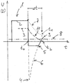
- FIG. 1 the course of the voltage U (solid line) 2 applied to a winding and the corresponding current I (broken line) 3 is plotted against time t in a diagram.
- a voltage pulse 1 is shown, as can be generated in the case of a block control on the winding of an electronically commutated direct current motor.
- the applied voltage 2 is interrupted at time t 0 , the voltage 2 drops abruptly and reverses its sign.
- the level 4 of the negative voltage is due to the resistance in the winding. To avoid overvoltage, the voltage is limited to a value of 5 by a diode.
- Time measurement is started at time t 0 .
- the voltage across the winding is observed at least insofar as it is registered that it has been exceeded above a predetermined threshold 8, which in this case is in the positive range.
- a predetermined threshold 8 which in this case is in the positive range.
- the time measurement is stopped and the length of the interval ⁇ t is registered.
- the time t 1 almost coincides with the complete drop in the current I at the time t 2 , which corresponds to the time at which the voltage actually induced in the winding intersects the theoretical profile of the BEMF 7 at point 9.
Landscapes
- Physics & Mathematics (AREA)
- General Physics & Mathematics (AREA)
- Control Of Motors That Do Not Use Commutators (AREA)
- Measurement Of Current Or Voltage (AREA)
- Tests Of Circuit Breakers, Generators, And Electric Motors (AREA)
Applications Claiming Priority (2)
| Application Number | Priority Date | Filing Date | Title |
|---|---|---|---|
| DE2000113537 DE10013537A1 (de) | 2000-03-20 | 2000-03-20 | Verfahren zur Strommessung |
| DE10013537 | 2000-03-20 |
Publications (3)
| Publication Number | Publication Date |
|---|---|
| EP1136828A2 true EP1136828A2 (fr) | 2001-09-26 |
| EP1136828A3 EP1136828A3 (fr) | 2003-07-09 |
| EP1136828B1 EP1136828B1 (fr) | 2007-04-25 |
Family
ID=7635466
Family Applications (1)
| Application Number | Title | Priority Date | Filing Date |
|---|---|---|---|
| EP20010106101 Expired - Lifetime EP1136828B1 (fr) | 2000-03-20 | 2001-03-13 | Procédé de mesure de courant |
Country Status (2)
| Country | Link |
|---|---|
| EP (1) | EP1136828B1 (fr) |
| DE (2) | DE10013537A1 (fr) |
Cited By (3)
| Publication number | Priority date | Publication date | Assignee | Title |
|---|---|---|---|---|
| WO2010046386A3 (fr) * | 2008-10-23 | 2010-07-15 | Hella Kgaa Hueck & Co. | Procédé d'utilisation d'un moteur électrique |
| WO2016001194A1 (fr) * | 2014-06-30 | 2016-01-07 | Elmos Semiconductor Aktiengesellschaft | Procédé d'acquisition d'un renseignement, en particulier d'un renseignement initial sur une condition de charge potentiellement incorrecte d'un moteur électrique à plusieurs phases |
| EP1933453A3 (fr) * | 2006-12-14 | 2017-04-19 | Wilo Ag | Procédé destiné à la commande d'un moteur pas à pas |
Families Citing this family (1)
| Publication number | Priority date | Publication date | Assignee | Title |
|---|---|---|---|---|
| DE102013220995B4 (de) | 2013-06-21 | 2018-06-21 | Continental Automotive Gmbh | Erkennung eines Drahtbruchfehlers beim Betrieb eines bürstenlosen Gleichstrommotors |
Family Cites Families (8)
| Publication number | Priority date | Publication date | Assignee | Title |
|---|---|---|---|---|
| US4204425A (en) * | 1978-06-29 | 1980-05-27 | Westinghouse Electric Corp. | Method of testing induction motors |
| US4670698A (en) * | 1983-12-02 | 1987-06-02 | Imec Corporation | Adaptive induction motor controller |
| US4744041A (en) * | 1985-03-04 | 1988-05-10 | International Business Machines Corporation | Method for testing DC motors |
| US5115174A (en) * | 1989-01-18 | 1992-05-19 | Hitachi, Ltd. | Method of controlling brushless DC motor |
| NZ280025A (en) * | 1990-12-19 | 1997-12-19 | Fisher & Paykel | Speed control of multiphase electronically controlled motor |
| EP0848259A1 (fr) * | 1996-12-16 | 1998-06-17 | Motorola Semiconducteurs S.A. | Circuit de détection de décrochage d'un moteur et méthode de détection de décrochage d'un moteur |
| DK0972332T3 (da) * | 1997-02-05 | 2004-07-26 | Fisher & Paykel Appliances Ltd | Styring af börstelös jævnströmsmotor |
| DE19837796A1 (de) * | 1998-08-20 | 2000-02-24 | Wilo Gmbh | Verfahren zur Ermittlung des Pumpenzustandes |
-
2000
- 2000-03-20 DE DE2000113537 patent/DE10013537A1/de not_active Withdrawn
-
2001
- 2001-03-13 EP EP20010106101 patent/EP1136828B1/fr not_active Expired - Lifetime
- 2001-03-13 DE DE50112391T patent/DE50112391D1/de not_active Expired - Fee Related
Cited By (13)
| Publication number | Priority date | Publication date | Assignee | Title |
|---|---|---|---|---|
| EP1933453A3 (fr) * | 2006-12-14 | 2017-04-19 | Wilo Ag | Procédé destiné à la commande d'un moteur pas à pas |
| US8810180B2 (en) | 2008-10-23 | 2014-08-19 | Zentrum Mikroelektronik Dresden Ag | Electric motor operation apparatus and method |
| KR101310193B1 (ko) | 2008-10-23 | 2013-09-24 | 첸트룸 미크로엘렉트로닉 드레스덴 악치엔게젤샤프트 | 전기 모터를 동작시키기 위한 방법 |
| WO2010046386A3 (fr) * | 2008-10-23 | 2010-07-15 | Hella Kgaa Hueck & Co. | Procédé d'utilisation d'un moteur électrique |
| CN102227871B (zh) * | 2008-10-23 | 2015-03-25 | 核心微电子德累斯顿股份公司 | 用于运行电动机的方法 |
| CN102227871A (zh) * | 2008-10-23 | 2011-10-26 | 核心微电子德累斯顿股份公司 | 用于运行电动机的方法 |
| WO2016001194A1 (fr) * | 2014-06-30 | 2016-01-07 | Elmos Semiconductor Aktiengesellschaft | Procédé d'acquisition d'un renseignement, en particulier d'un renseignement initial sur une condition de charge potentiellement incorrecte d'un moteur électrique à plusieurs phases |
| CN106664051A (zh) * | 2014-06-30 | 2017-05-10 | 艾尔默斯半导体股份公司 | 用于获得对多相电动机的可能的有故障的负载状况的提示、尤其是开始提示的方法 |
| EP3428668A1 (fr) * | 2014-06-30 | 2019-01-16 | ELMOS Semiconductor AG | Procédé d'obtention d'une instruction, en particulier d'une instruction initiale sur une condition de charge possible erronée d'un moteur électrique multiphase |
| EP3428667A1 (fr) * | 2014-06-30 | 2019-01-16 | ELMOS Semiconductor AG | Procédé d'obtention d'une instruction, en particulier d'une instruction initiale sur une condition de charge possible erronée d'un moteur électrique multiphase |
| US10338142B2 (en) | 2014-06-30 | 2019-07-02 | Elmos Semiconductor Ag | Faulty load detection for multi-phase electric motor |
| US10620268B2 (en) | 2014-06-30 | 2020-04-14 | Elmos Semiconductor Ag | Faulty load detection for multi-phase electric motor |
| US10768235B2 (en) | 2014-06-30 | 2020-09-08 | Elmos Semiconductor Aktiengesellschaft | Faulty load detection for multi-phase electric motor |
Also Published As
| Publication number | Publication date |
|---|---|
| EP1136828B1 (fr) | 2007-04-25 |
| DE50112391D1 (de) | 2007-06-06 |
| DE10013537A1 (de) | 2001-09-27 |
| EP1136828A3 (fr) | 2003-07-09 |
Similar Documents
| Publication | Publication Date | Title |
|---|---|---|
| DE4124240C2 (de) | Verfahren zur Regelung des Motorstroms eines bürstenlosen Gleichstommotors | |
| DE3706659C2 (fr) | ||
| EP0657989B1 (fr) | Méthode pour influencer la vitesse pour moteur à courant continu sans collecteur et moteur à courant continu sans collecteur pour sa mise en oeuvre | |
| DE4009184C2 (fr) | ||
| DE19860446A1 (de) | Verfahren zur Regelung eines spannungs-/frequenzumrichtergesteuerten Mehrphasen-Permanentmagnetmotors | |
| EP2107677B1 (fr) | Moteur électrique commuté électroniquement | |
| DE2556726B2 (de) | Steuerschaltung fuer einen selbstanlaufenden elektromotor | |
| WO2011026489A2 (fr) | Procédé et circuiterie pour détecter la charge d'un moteur, sans capteur, et pour réguler l'intensité en fonction de la valeur de la charge dans des moteurs pas-à-pas | |
| EP1929622B1 (fr) | Procede pour alimenter en energie un moteur a courant continu pouvant etre commute electroniquement par l'intermediaire d'un terminal a semi-conducteurs | |
| DE4425193C1 (de) | Drehzahlverstellbarer EC-Gleichstrommotor | |
| EP1136828A2 (fr) | Procédé de mesure de courant | |
| EP1531543A2 (fr) | Méthode de contrôle PWM du courant dans un moteur électrique à enroulements multiples | |
| BE1026445B1 (de) | Geräteschutzschalter mit intelligenter Grenzwertermittlung | |
| DE102013021975A1 (de) | Elektronische Anlaufschaltung für einen Einphasen-Induktionsmotor | |
| EP1443635B1 (fr) | Procédé de contrôle d'un angle d'allumage et moteur électrique alimenté en courant monophasé | |
| DE4123105A1 (de) | Verfahren und vorrichtung zur regelung der ansteuerleistung elektrischer verbraucher | |
| DE102006004313A1 (de) | Verfahren zur Steuerung eines Gleichspannungs-Elektromotors | |
| DE102007028083A1 (de) | pi-Filter mit Begrenzung des Eingangsstroms | |
| EP0948126A2 (fr) | Dispositif de détection de paramètre d'un moteur asynchrone | |
| DE102006001915B4 (de) | Verfahren und Anordnung zur Ermittlung von Betriebsgrößen eines EC-Motors | |
| DE4200983A1 (de) | Bremsschaltung fuer kleine universalmotoren | |
| DE202004020586U1 (de) | Überlastschutz von bürstenlosen Motoren | |
| WO2004040747A1 (fr) | Procede de commutation d'un circuit en pont | |
| DE9204811U1 (de) | Ansteuerschaltung für kollektorlosen Gleichstrommotor | |
| DE29507982U1 (de) | Elektrogerät |
Legal Events
| Date | Code | Title | Description |
|---|---|---|---|
| PUAI | Public reference made under article 153(3) epc to a published international application that has entered the european phase |
Free format text: ORIGINAL CODE: 0009012 |
|
| AK | Designated contracting states |
Kind code of ref document: A2 Designated state(s): AT BE CH CY DE DK ES FI FR GB GR IE IT LI LU MC NL PT SE TR |
|
| AX | Request for extension of the european patent |
Free format text: AL;LT;LV;MK;RO;SI |
|
| PUAL | Search report despatched |
Free format text: ORIGINAL CODE: 0009013 |
|
| AK | Designated contracting states |
Designated state(s): AT BE CH CY DE DK ES FI FR GB GR IE IT LI LU MC NL PT SE TR |
|
| AX | Request for extension of the european patent |
Extension state: AL LT LV MK RO SI |
|
| 17P | Request for examination filed |
Effective date: 20031220 |
|
| AKX | Designation fees paid |
Designated state(s): DE FR GB IT |
|
| 17Q | First examination report despatched |
Effective date: 20040218 |
|
| RAP1 | Party data changed (applicant data changed or rights of an application transferred) |
Owner name: PIERBURG GMBH |
|
| GRAP | Despatch of communication of intention to grant a patent |
Free format text: ORIGINAL CODE: EPIDOSNIGR1 |
|
| GRAS | Grant fee paid |
Free format text: ORIGINAL CODE: EPIDOSNIGR3 |
|
| RIN1 | Information on inventor provided before grant (corrected) |
Inventor name: KATZER, STEFFEN Inventor name: STEPHAN, WALDEMAR Inventor name: LELITKO, UDO |
|
| GRAA | (expected) grant |
Free format text: ORIGINAL CODE: 0009210 |
|
| AK | Designated contracting states |
Kind code of ref document: B1 Designated state(s): DE FR GB IT |
|
| REG | Reference to a national code |
Ref country code: GB Ref legal event code: FG4D Free format text: NOT ENGLISH |
|
| REF | Corresponds to: |
Ref document number: 50112391 Country of ref document: DE Date of ref document: 20070606 Kind code of ref document: P |
|
| GBT | Gb: translation of ep patent filed (gb section 77(6)(a)/1977) |
Effective date: 20070628 |
|
| ET | Fr: translation filed | ||
| PLBE | No opposition filed within time limit |
Free format text: ORIGINAL CODE: 0009261 |
|
| STAA | Information on the status of an ep patent application or granted ep patent |
Free format text: STATUS: NO OPPOSITION FILED WITHIN TIME LIMIT |
|
| 26N | No opposition filed |
Effective date: 20080128 |
|
| PGFP | Annual fee paid to national office [announced via postgrant information from national office to epo] |
Ref country code: GB Payment date: 20090324 Year of fee payment: 9 |
|
| PGFP | Annual fee paid to national office [announced via postgrant information from national office to epo] |
Ref country code: DE Payment date: 20090525 Year of fee payment: 9 Ref country code: IT Payment date: 20090326 Year of fee payment: 9 |
|
| PGFP | Annual fee paid to national office [announced via postgrant information from national office to epo] |
Ref country code: FR Payment date: 20090318 Year of fee payment: 9 |
|
| GBPC | Gb: european patent ceased through non-payment of renewal fee |
Effective date: 20100313 |
|
| REG | Reference to a national code |
Ref country code: FR Ref legal event code: ST Effective date: 20101130 |
|
| PG25 | Lapsed in a contracting state [announced via postgrant information from national office to epo] |
Ref country code: FR Free format text: LAPSE BECAUSE OF NON-PAYMENT OF DUE FEES Effective date: 20100331 |
|
| PG25 | Lapsed in a contracting state [announced via postgrant information from national office to epo] |
Ref country code: DE Free format text: LAPSE BECAUSE OF NON-PAYMENT OF DUE FEES Effective date: 20101001 |
|
| PG25 | Lapsed in a contracting state [announced via postgrant information from national office to epo] |
Ref country code: GB Free format text: LAPSE BECAUSE OF NON-PAYMENT OF DUE FEES Effective date: 20100313 Ref country code: IT Free format text: LAPSE BECAUSE OF NON-PAYMENT OF DUE FEES Effective date: 20100313 |