EP1136828A2 - Method for measuring current - Google Patents
Method for measuring current Download PDFInfo
- Publication number
- EP1136828A2 EP1136828A2 EP01106101A EP01106101A EP1136828A2 EP 1136828 A2 EP1136828 A2 EP 1136828A2 EP 01106101 A EP01106101 A EP 01106101A EP 01106101 A EP01106101 A EP 01106101A EP 1136828 A2 EP1136828 A2 EP 1136828A2
- Authority
- EP
- European Patent Office
- Prior art keywords
- voltage
- time
- current
- time interval
- supply voltage
- Prior art date
- Legal status (The legal status is an assumption and is not a legal conclusion. Google has not performed a legal analysis and makes no representation as to the accuracy of the status listed.)
- Granted
Links
Images
Classifications
-
- G—PHYSICS
- G01—MEASURING; TESTING
- G01R—MEASURING ELECTRIC VARIABLES; MEASURING MAGNETIC VARIABLES
- G01R19/00—Arrangements for measuring currents or voltages or for indicating presence or sign thereof
- G01R19/175—Indicating the instants of passage of current or voltage through a given value, e.g. passage through zero
-
- G—PHYSICS
- G01—MEASURING; TESTING
- G01R—MEASURING ELECTRIC VARIABLES; MEASURING MAGNETIC VARIABLES
- G01R31/00—Arrangements for testing electric properties; Arrangements for locating electric faults; Arrangements for electrical testing characterised by what is being tested not provided for elsewhere
- G01R31/34—Testing dynamo-electric machines
- G01R31/343—Testing dynamo-electric machines in operation
Definitions
- the present invention relates to a method for measuring the current consumption of an electric motor regulated by means of control electronics, the stator with a stator winding and a rotor equipped with permanent magnets has, an external supply voltage at the stator winding can be created.
- the value of the current is an important one Information for the power regulation or for the realization of a Overload shutdown.
- the current strength in the windings measured across the voltage drop across a resistor is particularly small and with simply constructed motors disadvantageous, since additional components are required with the resistors on the one hand increase the installation space of the engine and on the other hand the Burden manufacturing costs. In addition, each is generally additional required component reduces the operational safety of the entire engine. Similar Problems arise with another type of current measurement, in which the Voltage drop across a bridge transistor is determined. It also includes disadvantageous that a high resolution of the Voltage measurement is necessary, which requires additional technical effort goes along.
- the object of the invention is therefore to provide a method for measuring current in To create electric motors that reduce the number of components and thus the Construction size allowed and to increase operational safety and to Contributes to a reduction in manufacturing costs,
- the essential idea of the invention is that instead of an absolute Voltage is just a time interval between two easily definable points in time is measured and that from the length of the interval to the interested Current strength is closed.
- the advantages of the invention result from the fact that such a time measurement is technically much easier is to be carried out as an absolute voltage measurement. It will Defined time interval from the course of the induced voltage defined that occurs in the winding after the supply voltage has been switched off. From the Course of the induced voltage can affect the course of the current and above all the current strength at the beginning of the time interval can be inferred.
- the basic steps of the method according to the invention are the following:
- the supply voltage applied to the winding is switched off abruptly. This breaks the tension in the winding and reverses its sign.
- the strength of this induced voltage of the opposite sign depends on the size of the resistance of the winding. Then the induced voltage feeds the value zero and exceeds this value on the one hand because of the low resistance which causes a damping of the vibration in a plurality of periods, and on the other hand orce due to the heat generated by the rotating rotor back induced voltage (B ack E lectro M agnetic F , BEMF).
- B ack E lectro M agnetic F BEMF
- the current intensity becomes zero at the point where the induced voltage has also become zero and where the voltage in the winding is formed only by the BEMF. Since the current strength has dropped exponentially, the current interval at the time of the switch-off can be inferred from the time interval between the switching off of the voltage and the zero crossing of the induced voltage. The invention makes use of this effect.
- a voltage level is set as a threshold above the zero voltage, and the time is measured until the voltage in the winding has exceeded this level.
- This positive threshold forms a value that is easier to define and therefore easier to measure than the zero crossing.
- the time measurement is stopped. The length of the measured time interval, ie the time until the level is reached, is - as explained - dependent on the current intensity prevailing before the time t 0 , a slight correction being taken into account.
- the method according to the invention can advantageously be used in the case of (block) control of the electric motor by means of a square-wave voltage, since the square-wave voltage abruptly breaks off at the edges and the effects mentioned can be exploited.
- the method can be used particularly advantageously in the case of electronically commutated direct current motors which have control electronics with power semiconductors. With these motors, any voltage can be generated by pulse width modulation.
- the supply voltage can be switched off abruptly in a simple manner. It is possible to give the supply voltage a harmonic course, in particular the course of a sinusoidal voltage, and to interrupt the supply voltage at time t 0 for the duration of a measuring interval ⁇ t.
- the existing microprocessor with its Clock can be used to measure time and exceeding of the voltage level.
- the microprocessor can also do that Conversion from the length of the time interval to the current strength using a Make function or a table. Measuring the time interval is advantageously done by counting high-frequency pulses, the Pulses in particular have a frequency of 1 to 5 MHz. Without too Using the clock frequency of a microprocessor can be simple and inexpensive counter / timer modules in the control electronics of electric motors integrate.
- this pump Because of the particularly good running properties of the engine, it is advantageous use this to operate a centrifugal pump. Because of the low cost and the small size, this pump is particularly good for the operation of Use heating or cooling circuits, especially in motor vehicles.
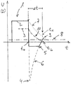
- FIG. 1 the course of the voltage U (solid line) 2 applied to a winding and the corresponding current I (broken line) 3 is plotted against time t in a diagram.
- a voltage pulse 1 is shown, as can be generated in the case of a block control on the winding of an electronically commutated direct current motor.
- the applied voltage 2 is interrupted at time t 0 , the voltage 2 drops abruptly and reverses its sign.
- the level 4 of the negative voltage is due to the resistance in the winding. To avoid overvoltage, the voltage is limited to a value of 5 by a diode.
- Time measurement is started at time t 0 .
- the voltage across the winding is observed at least insofar as it is registered that it has been exceeded above a predetermined threshold 8, which in this case is in the positive range.
- a predetermined threshold 8 which in this case is in the positive range.
- the time measurement is stopped and the length of the interval ⁇ t is registered.
- the time t 1 almost coincides with the complete drop in the current I at the time t 2 , which corresponds to the time at which the voltage actually induced in the winding intersects the theoretical profile of the BEMF 7 at point 9.
Landscapes
- Physics & Mathematics (AREA)
- General Physics & Mathematics (AREA)
- Control Of Motors That Do Not Use Commutators (AREA)
- Measurement Of Current Or Voltage (AREA)
- Tests Of Circuit Breakers, Generators, And Electric Motors (AREA)
Abstract
Verfahren zur Messung der Stromaufnahme eines mit einer Steuerelektronik
geregelten Elektromotors, der einen Stator mit einer Statorwicklung und einen
mit Permanentmagneten bestückten Rotor aufweist, wobei an der
Statorwicklung eine externe Versorgungsspannung anlegbar ist, wobei die
angelegte Versorgungsspannung zu einem Zeitpunkt t0 abgeschaltet wird,
nachfolgend die an der Wicklung anliegende Spannung gemessen und mit
einem vorgegebenen Spannungslevel verglichen wird und das Zeitintervall
gemessen wird, das zwischen dem Zeitpunkt t0 und dem Erreichen des
Spannungslevels durch die induzierte Spannung liegt, wobei die Länge des
Zeitintervalles in Bezug zur Stromstärke zum Zeitpunkt t0 setzbar ist.
Description
Die vorliegende Erfindung betrifft ein Verfahren zur Messung der Stromaufnahme eines vermittels einer Steuerelektronik geregelten Elektromotors, der einen Stator mit einer Statorwicklung und einen mit Permanentmagneten bestückten Rotor aufweist, wobei an der Statorwicklung eine externe Versorgungsspannung anlegbar ist.The present invention relates to a method for measuring the current consumption of an electric motor regulated by means of control electronics, the stator with a stator winding and a rotor equipped with permanent magnets has, an external supply voltage at the stator winding can be created.
Bei derartigen Elektromotoren ist der Wert der Stromstärke eine wichtige Information für die Leistungsregelung oder zur Realisierung einer Überlastabschaltung. Bekanntermaßen wird die Stromstärke in den Wicklungen über den Spannungsabfall an einem Widerstand gemessen. Gerade bei besonders kleinen und bei einfach aufgebauten Motoren ist diese Art der Messung nachteilig, da mit den Widerständen zusätzliche Bauteile benötigt werden, die einerseits den Bauraum des Motors vergrößern und andererseits die Herstellungskosten belasten. Zudem wird generell durch jedes zusätzlich benötigte Bauteil die Betriebssicherheit des gesamten Motors verringert. Ähnliche Probleme ergeben sich bei einer anderen Art der Strommessung, bei der der Spannungsabfall über einem Brückentransistor bestimmt wird. Dabei ist zudem nachteilig, daß zur genauen Bestimmung des Stromes eine hohe Auflösung der Spannungsmessung notwendig ist, was mit zusätzlichem technischen Aufwand einhergeht. In such electric motors, the value of the current is an important one Information for the power regulation or for the realization of a Overload shutdown. As is known, the current strength in the windings measured across the voltage drop across a resistor. Especially with This type of measurement is particularly small and with simply constructed motors disadvantageous, since additional components are required with the resistors on the one hand increase the installation space of the engine and on the other hand the Burden manufacturing costs. In addition, each is generally additional required component reduces the operational safety of the entire engine. Similar Problems arise with another type of current measurement, in which the Voltage drop across a bridge transistor is determined. It also includes disadvantageous that a high resolution of the Voltage measurement is necessary, which requires additional technical effort goes along.
Aufgabe der Erfindung ist es daher, ein Verfahren zur Strommessung in Elektromotoren zu schaffen, das eine Reduzierung der Bauteile und damit der Baugröße erlaubt und zu einer Erhöhung der Betriebssicherheit und zu einer Minderung der Herstellungskosten beiträgt,The object of the invention is therefore to provide a method for measuring current in To create electric motors that reduce the number of components and thus the Construction size allowed and to increase operational safety and to Contributes to a reduction in manufacturing costs,
Diese Aufgabe wird durch ein Verfahren wie in Anspruch 1 beschrieben gelöst.This object is achieved by a method as described in claim 1.
Der erfindungswesentliche Gedanke liegt darin, daß statt einer absoluten Spannung lediglich ein Zeitintervall zwischen zwei leicht definierbaren Zeitpunkten gemessen wird und daß aus der Länge des Intervalls auf die interessierende Stromstärke zurückgeschlossen wird. Die Vorteile der Erfindung resultieren daraus, daß eine solche Zeitmessung technisch wesentlich einfacher durchzuführen ist, als eine absolute Spannungsmessung. Dabei wird das auszumessende Zeitintervall vom Verlauf der induzierten Spannung definiert, die nach dem Abschalten der Versorgungsspannung in der Wicklung auftritt. Aus dem Verlauf der induzierten Spannung kann auf den Verlauf des Stromes und vor allem auf die Stromstärke zum Beginn des Zeitintervalls zurückgeschlossen werden. Die grundlegenden Schritte des erfindungsgemäßen Verfahrens sind die folgenden:The essential idea of the invention is that instead of an absolute Voltage is just a time interval between two easily definable points in time is measured and that from the length of the interval to the interested Current strength is closed. The advantages of the invention result from the fact that such a time measurement is technically much easier is to be carried out as an absolute voltage measurement. It will Defined time interval from the course of the induced voltage defined that occurs in the winding after the supply voltage has been switched off. From the Course of the induced voltage can affect the course of the current and above all the current strength at the beginning of the time interval can be inferred. The basic steps of the method according to the invention are the following:
Zu einem Zeitpunkt t0 wird die an der Wicklung anliegende Versorgungsspannung abrupt abgeschaltet. Damit bricht die Spannung in der Wicklung zusammen und kehrt ihr Vorzeichen um. Die Stärke dieser induzierten Spannung umgekehrten Vorzeichens hängt dabei von der Größe des Widerstandes der Wicklung ab. Die induzierte Spannung nährt sich daraufhin dem Wert Null und überschreitet diesen Wert einerseits wegen des geringen Widerstandes, der eine Dämpfung der Schwingung in mehreren Perioden bewirkt, und andererseits wegen der durch den sich drehenden Rotor erzeugten rückinduzierten Spannung (Back ElectroMagnetic Force, BEMF). Die tatsächliche in der Wicklung vorhandene Spannung ist somit eine Addition beider Spannungen. In der Zwischenzeit nimmt auch die ursprünglich vorhandene Stromstärke langsam ab. Die Stromstärke wird an dem Punkt zu Null, wo auch die induzierte Spannung zu Null geworden ist und wo die Spannung in der Wicklung lediglich durch die BEMF gebildet wird. Da die Stromstärke exponentiell abgefallen ist, läßt sich aus dem Zeitintervall zwischen dem Abschalten der Spannung und dem Nulldurchgang der induzierten Spannung auf die Stromstärke zum Zeitpunkt der Abschaltung schließen. Diesen Effekt macht sich die Erfindung zunutze.At a time t 0 , the supply voltage applied to the winding is switched off abruptly. This breaks the tension in the winding and reverses its sign. The strength of this induced voltage of the opposite sign depends on the size of the resistance of the winding. Then the induced voltage feeds the value zero and exceeds this value on the one hand because of the low resistance which causes a damping of the vibration in a plurality of periods, and on the other hand orce due to the heat generated by the rotating rotor back induced voltage (B ack E lectro M agnetic F , BEMF). The actual voltage present in the winding is thus an addition of both voltages. In the meantime, the current strength that was originally present is slowly decreasing. The current intensity becomes zero at the point where the induced voltage has also become zero and where the voltage in the winding is formed only by the BEMF. Since the current strength has dropped exponentially, the current interval at the time of the switch-off can be inferred from the time interval between the switching off of the voltage and the zero crossing of the induced voltage. The invention makes use of this effect.
Wegen des Vorhandenseins der BEMF entspricht der Nulldurchgang der tatsächlich an der Wicklung vorhandenen Spannung nicht dem Nulldurchgang der induzierten Spannung, der später erfolgen würde. Aus diesem Grunde und aus Gründen der Praktikabilität wird ein Spannungslevel als Schwelle über der Nullspannung gesetzt, und die Zeit gemessen, bis die Spannung in der Wicklung diesen Level überschritten hat. Diese positive Schwelle bildet einen besser zu definierenden und daher besser zu messenden Wert als der Nulldurchgang. Sobald festgestellt wurde, daß der Level überschritten ist, wird die Zeitmessung gestoppt. Die Länge des gemessenen Zeitintervalls, d.h. die Zeit bis zum Erreichen des Levels, ist - wie dargelegt - abhängig von der vor dem Zeitpunkt t0 herrschenden Stromstärke, wobei eine geringe Korrektur zu berücksichtigen ist.Because of the presence of the BEMF, the zero crossing of the voltage actually present on the winding does not correspond to the zero crossing of the induced voltage that would occur later. For this reason and for reasons of practicability, a voltage level is set as a threshold above the zero voltage, and the time is measured until the voltage in the winding has exceeded this level. This positive threshold forms a value that is easier to define and therefore easier to measure than the zero crossing. As soon as it has been determined that the level has been exceeded, the time measurement is stopped. The length of the measured time interval, ie the time until the level is reached, is - as explained - dependent on the current intensity prevailing before the time t 0 , a slight correction being taken into account.
Die aus dem Verfahren resultierenden Vorteile liegen auf der Hand. So kann einerseits auf die "Shunt"-Widerstände, die zur Messung des Stromes anhand des Spannungsabfalls nötig waren, verzichtet werden. Dieser Verzicht geht mit einer Senkung der Herstellungskosten, einer Reduzierung des Bauraumes und mit einer Erhöhung der Betriebssicherheit einher. Andererseits zeichnet sich das erfindungsgemäße Verfahren durch eine hohe Auflösung und eine große Genauigkeit der Strommessung aus. Damit trägt es zu einer Verbesserung der Regelung und damit zu einer Optimierung der Laufeigenschaften des Motors bei.The advantages resulting from the process are obvious. So can on the one hand to the "shunt" resistors used to measure the current using the Voltage drop were necessary to be dispensed with. This waiver goes with one Reduction in manufacturing costs, a reduction in installation space and with one Increased operational security. On the other hand, that's what distinguishes it method according to the invention by a high resolution and a large Accuracy of current measurement. It thus helps to improve Regulation and thus an optimization of the running properties of the engine.
Das erfindungsgemäße Verfahren läßt sich bei einer (Block)-Ansteuerung des Elektromotors durch eine Rechteckspannung vorteilhaft einsetzen, da die Rechteckspannung an den Flanken abrupt abbricht und die genannten Effekte ausgenutzt werden können. Besonders vorteilhaft läßt sich das Verfahren jedoch bei elektronisch kommutierten Gleichstrommotoren einsetzen, die über eine Steuerelektronik mit Leistungshalbleitern verfügen. Bei diesen Motoren läßt sich jede beliebige Spannung durch Pulsweitenmodulation erzeugen. Insbesondere kann die Versorgungsspannung auf einfache Weise abrupt abgeschaltet werden. Es ist möglich, der Versorgungsspannung einen harmonischen Verlauf insbesondere den Verlauf einer Sinusspannung zu geben, und die Versorgungsspannung zum Zeitpunkt t0 für die Dauer eines Meßintervalls Δt zu unterbrechen.The method according to the invention can advantageously be used in the case of (block) control of the electric motor by means of a square-wave voltage, since the square-wave voltage abruptly breaks off at the edges and the effects mentioned can be exploited. However, the method can be used particularly advantageously in the case of electronically commutated direct current motors which have control electronics with power semiconductors. With these motors, any voltage can be generated by pulse width modulation. In particular, the supply voltage can be switched off abruptly in a simple manner. It is possible to give the supply voltage a harmonic course, in particular the course of a sinusoidal voltage, and to interrupt the supply voltage at time t 0 for the duration of a measuring interval Δt.
Es ist zudem vorteilhaft, daß der vorhandene Mikroprozessor mit seinem Taktgeber benutzt werden kann, um die Zeit zu messen und das Überschreiten des Spannungslevels festzustellen. Der Mikroprozessor kann auch die Umrechnung von der Länge des Zeitintervalls zur Stromstärke anhand einer Funktion oder einer Tabelle vornehmen. Das Ausmessen des Zeitintervalles geschieht vorteilhafter Weise durch Zählen von hochfrequenten Pulsen, wobei die Pulse insbesondere eine Frequenz von 1 bis 5 MHz aufweisen. Auch ohne Verwendung der Taktfrequenz eines Mikroprozessors lassen sich einfache und preiswerte Counter/Timer Bausteine in die Steuerelektronik von Elektromotoren integrieren.It is also advantageous that the existing microprocessor with its Clock can be used to measure time and exceeding of the voltage level. The microprocessor can also do that Conversion from the length of the time interval to the current strength using a Make function or a table. Measuring the time interval is advantageously done by counting high-frequency pulses, the Pulses in particular have a frequency of 1 to 5 MHz. Without too Using the clock frequency of a microprocessor can be simple and inexpensive counter / timer modules in the control electronics of electric motors integrate.
Es ist wegen der besonders guten Laufeigenschaften des Motors vorteilhaft, diesen zum Betrieb einer Kreiselpumpe einzusetzen. Wegen der geringen Kosten und der geringen Baugröße läßt sich diese Pumpe besonders gut zum Betrieb von Heiz- oder Kühlkreisläufen insbesondere in Kraftfahrzeugen einsetzen.Because of the particularly good running properties of the engine, it is advantageous use this to operate a centrifugal pump. Because of the low cost and the small size, this pump is particularly good for the operation of Use heating or cooling circuits, especially in motor vehicles.
Eine besondere Ausführungsform des erfindungsgemäßen Verfahrens wird anhand der Figur nachfolgend näher beschrieben.A special embodiment of the method according to the invention is described in more detail below with reference to the figure.
In der Figur ist der Verlauf der an einer Wicklung anliegenden Spannung U (durchgezogene Linie) 2 und des entsprechenden Stromes I (unterbrochene Linie) 3 gegen die Zeit t in einem Diagramm aufgetragen. Dargestellt ist ein Spannungspuls 1, wie er bei einer Blockansteuerung an der Wicklung eines elektronisch kommutierten Gleichstrommotors generierbar ist. Die anliegende Spannung 2 wird zum Zeitpunkt t0 unterbrochen die Spannung 2 fällt abrupt ab und kehrt ihr Vorzeichen um. Die Höhe 4 der negativen Spannung ist bedingt durch den Widerstand in der Wicklung. Um eine Überspannung zu vermeiden wird die Spannung durch eine Diode auf einen Wert 5 beschränkt. Zum Zeitpunkt wird t0 die Zeitmessung gestartet. In the figure, the course of the voltage U (solid line) 2 applied to a winding and the corresponding current I (broken line) 3 is plotted against time t in a diagram. A voltage pulse 1 is shown, as can be generated in the case of a block control on the winding of an electronically commutated direct current motor. The applied voltage 2 is interrupted at time t 0 , the voltage 2 drops abruptly and reverses its sign. The level 4 of the negative voltage is due to the resistance in the winding. To avoid overvoltage, the voltage is limited to a value of 5 by a diode. Time measurement is started at time t 0 .
Nachdem die Spannung 2 in der Wicklung ihr negatives Maximum 4 erreicht hat,
steigt sie entlang der Kurve 6 wieder an. Dabei ist zu beachten, daß der
dargestellte Verlauf der an der Wicklung tatsächlich anliegenden Spannung die
Summe aus der induzierten und der durch den sich drehenden Rotor
rückinduzierten Spannung 7 ist.After the voltage 2 in the winding has reached its negative maximum 4,
it rises again along
Nach dem Startzeitpunkt t0 wird die an der Wicklung liegende Spannung
zumindest insofern beobachtet, als ihr Überschreiten über eine vorgegebene
Schwelle 8, die in diesem Falle im positiven Bereich liegt, registriert wird. Zum
Zeitpunkt t1 des Übertrittes wird die Zeitmessung gestoppt und die Länge des
Intervalls Δt registriert. Dabei stimmt der Zeitpunkt t1 nahezu mit dem vollständigen
Abfall des Stromes I zum Zeitpunkt t2 überein, der dem Zeitpunkt entspricht, an
dem die tatsächlich in der Wicklung induzierte Spannung den theoretischen
Verlauf der BEMF 7 am Punkt 9 schneidet.After the starting point in time t 0 , the voltage across the winding is observed at least insofar as it is registered that it has been exceeded above a
Mit der Kenntnis des exponentiellen Stromabfalls 10 wird aus dem Zeitintervall Δt die ursprüngliche Stromstärke 2 ermittelt.With the knowledge of the exponential current drop 10, the time interval becomes Δt the original current 2 determined.
Claims (10)
dadurch gekennzeichnet,daß
characterized in that
dadurch gekennzeichnet, daß dem Zeitintervall eine Stromstärke (3) zugeordnet wird.Method according to claim 1,
characterized in that a current (3) is assigned to the time interval.
dadurch gekennzeichnet, daß der Elektromotor ein elektronisch kommutierter Gleichstrommotor ist.The method of claim 1 or 2,
characterized in that the electric motor is an electronically commutated DC motor.
dadurch gekennzeichnet , daß die Länge des Zeitintervalls Δt durch Zählen von hochfrequenten Pulsen gemessen wird. Method according to one of the preceding claims,
characterized in that the length of the time interval Δt is measured by counting high-frequency pulses.
dadurch gekennzeichnet, daß der Spannungslevel (8) auf einen Wert gelegt wird, der in Bezug auf die abgeschaltete Versorgungsspannung (2) dasselbe Vorzeichen hat.Method according to one of the preceding claims,
characterized in that the voltage level (8) is set to a value which has the same sign with respect to the switched-off supply voltage (2).
dadurch gekennzeichnet, daß die Versorgungsspannung (2) einen harmonischen Verlauf insbesondere den einer Sinusspannung hat, der zum Zeitpunkt t0 für ein Meßintervall unterbrochen wird.Method according to one of the preceding claims,
characterized in that the supply voltage (2) has a harmonic profile, in particular that of a sinusoidal voltage, which is interrupted at time t 0 for a measuring interval.
dadurch gekennzeichnet , daß die Versorgungsspannung (2) von Pulsen mit steil abfallender Flanke insbesondere von rechteckigen Pulsen gebildet wird, wobei zwischen den Pulsen eine spannungslose Totzeit liegt, die länger als ein Meßintervall ist.Method according to one of the preceding claims,
characterized in that the supply voltage (2) is formed by pulses with a steeply falling flank, in particular rectangular pulses, the dead time between the pulses being longer than a measurement interval.
dadurch gekennzeichnet, daß die Zuordnung von Zeitintervall und Stromstärke anhand einer Funktion oder einer Tabelle vorgenommen wird.Method according to one of the preceding claims,
characterized in that the assignment of time interval and current strength is carried out on the basis of a function or a table.
dadurch gekennzeichnet, daß die Zuordnung von einem Mikroprozessor vorgenommen wird, der Teil einer Steuerelektronik des Elektromotors ist.A method according to claim 8,
characterized in that the assignment is made by a microprocessor which is part of a control electronics of the electric motor.
dadurch gekennzeichnet , daß mit dem Elektromotor eine Kreiselpumpe betrieben wird.Method according to one of the preceding claims,
characterized in that a centrifugal pump is operated with the electric motor.
Applications Claiming Priority (2)
| Application Number | Priority Date | Filing Date | Title |
|---|---|---|---|
| DE2000113537 DE10013537A1 (en) | 2000-03-20 | 2000-03-20 | Current measurement method |
| DE10013537 | 2000-03-20 |
Publications (3)
| Publication Number | Publication Date |
|---|---|
| EP1136828A2 true EP1136828A2 (en) | 2001-09-26 |
| EP1136828A3 EP1136828A3 (en) | 2003-07-09 |
| EP1136828B1 EP1136828B1 (en) | 2007-04-25 |
Family
ID=7635466
Family Applications (1)
| Application Number | Title | Priority Date | Filing Date |
|---|---|---|---|
| EP20010106101 Expired - Lifetime EP1136828B1 (en) | 2000-03-20 | 2001-03-13 | Method for measuring current |
Country Status (2)
| Country | Link |
|---|---|
| EP (1) | EP1136828B1 (en) |
| DE (2) | DE10013537A1 (en) |
Cited By (3)
| Publication number | Priority date | Publication date | Assignee | Title |
|---|---|---|---|---|
| WO2010046386A3 (en) * | 2008-10-23 | 2010-07-15 | Hella Kgaa Hueck & Co. | Method for operating an electric motor |
| WO2016001194A1 (en) * | 2014-06-30 | 2016-01-07 | Elmos Semiconductor Aktiengesellschaft | Method for obtaining an indication, in particular a starting indication of a possible faulty load condition of a multi-phase electric motor |
| EP1933453A3 (en) * | 2006-12-14 | 2017-04-19 | Wilo Ag | Method for controlling a stepper motor |
Families Citing this family (1)
| Publication number | Priority date | Publication date | Assignee | Title |
|---|---|---|---|---|
| DE102013220995B4 (en) | 2013-06-21 | 2018-06-21 | Continental Automotive Gmbh | Detection of a wire break error during operation of a brushless DC motor |
Family Cites Families (8)
| Publication number | Priority date | Publication date | Assignee | Title |
|---|---|---|---|---|
| US4204425A (en) * | 1978-06-29 | 1980-05-27 | Westinghouse Electric Corp. | Method of testing induction motors |
| US4670698A (en) * | 1983-12-02 | 1987-06-02 | Imec Corporation | Adaptive induction motor controller |
| US4744041A (en) * | 1985-03-04 | 1988-05-10 | International Business Machines Corporation | Method for testing DC motors |
| US5115174A (en) * | 1989-01-18 | 1992-05-19 | Hitachi, Ltd. | Method of controlling brushless DC motor |
| NZ280025A (en) * | 1990-12-19 | 1997-12-19 | Fisher & Paykel | Speed control of multiphase electronically controlled motor |
| EP0848259A1 (en) * | 1996-12-16 | 1998-06-17 | Motorola Semiconducteurs S.A. | Stall detection circuit for a motor and method for detecting stalling of a motor |
| DK0972332T3 (en) * | 1997-02-05 | 2004-07-26 | Fisher & Paykel Appliances Ltd | Control of brushless DC motor |
| DE19837796A1 (en) * | 1998-08-20 | 2000-02-24 | Wilo Gmbh | Procedure for determining the pump condition |
-
2000
- 2000-03-20 DE DE2000113537 patent/DE10013537A1/en not_active Withdrawn
-
2001
- 2001-03-13 EP EP20010106101 patent/EP1136828B1/en not_active Expired - Lifetime
- 2001-03-13 DE DE50112391T patent/DE50112391D1/en not_active Expired - Fee Related
Cited By (13)
| Publication number | Priority date | Publication date | Assignee | Title |
|---|---|---|---|---|
| EP1933453A3 (en) * | 2006-12-14 | 2017-04-19 | Wilo Ag | Method for controlling a stepper motor |
| US8810180B2 (en) | 2008-10-23 | 2014-08-19 | Zentrum Mikroelektronik Dresden Ag | Electric motor operation apparatus and method |
| KR101310193B1 (en) | 2008-10-23 | 2013-09-24 | 첸트룸 미크로엘렉트로닉 드레스덴 악치엔게젤샤프트 | Method for operating an electric motor |
| WO2010046386A3 (en) * | 2008-10-23 | 2010-07-15 | Hella Kgaa Hueck & Co. | Method for operating an electric motor |
| CN102227871B (en) * | 2008-10-23 | 2015-03-25 | 核心微电子德累斯顿股份公司 | Method for operating electric motor |
| CN102227871A (en) * | 2008-10-23 | 2011-10-26 | 核心微电子德累斯顿股份公司 | Method for operating electric motor |
| WO2016001194A1 (en) * | 2014-06-30 | 2016-01-07 | Elmos Semiconductor Aktiengesellschaft | Method for obtaining an indication, in particular a starting indication of a possible faulty load condition of a multi-phase electric motor |
| CN106664051A (en) * | 2014-06-30 | 2017-05-10 | 艾尔默斯半导体股份公司 | Method for obtaining an indication, in particular starting an indication, of a possible faulty load situation of a polyphase motor |
| EP3428668A1 (en) * | 2014-06-30 | 2019-01-16 | ELMOS Semiconductor AG | Method for obtaining an indication, in particular an initial indication of a possible faulty load condition of a polyphase electric motor |
| EP3428667A1 (en) * | 2014-06-30 | 2019-01-16 | ELMOS Semiconductor AG | Method for obtaining an indication, in particular an initial indication of a possible faulty load condition of a polyphase electric motor |
| US10338142B2 (en) | 2014-06-30 | 2019-07-02 | Elmos Semiconductor Ag | Faulty load detection for multi-phase electric motor |
| US10620268B2 (en) | 2014-06-30 | 2020-04-14 | Elmos Semiconductor Ag | Faulty load detection for multi-phase electric motor |
| US10768235B2 (en) | 2014-06-30 | 2020-09-08 | Elmos Semiconductor Aktiengesellschaft | Faulty load detection for multi-phase electric motor |
Also Published As
| Publication number | Publication date |
|---|---|
| EP1136828B1 (en) | 2007-04-25 |
| DE50112391D1 (en) | 2007-06-06 |
| DE10013537A1 (en) | 2001-09-27 |
| EP1136828A3 (en) | 2003-07-09 |
Similar Documents
| Publication | Publication Date | Title |
|---|---|---|
| DE4124240C2 (en) | Process for controlling the motor current of a brushless DC motor | |
| DE3706659C2 (en) | ||
| EP0657989B1 (en) | Method for controlling the speed of a collectorless DC motor and collectorless DC motor for performing the method | |
| DE4009184C2 (en) | ||
| DE19860446A1 (en) | Method for controlling a voltage / frequency converter-controlled multi-phase permanent magnet motor | |
| EP2107677B1 (en) | Electronically commutated electric motor | |
| DE2556726B2 (en) | CONTROL CIRCUIT FOR A SELF-STARTING ELECTRIC MOTOR | |
| WO2011026489A2 (en) | Method and circuit arrangement for sensorless engine load detection and for controlling the motor current in accordance with the load value in stepper motors | |
| EP1929622B1 (en) | Method for supplying electrical power to a dc motor which can be commutated electronically via a semiconductor power output stage | |
| DE4425193C1 (en) | Variable speed EC direct current motor | |
| EP1136828A2 (en) | Method for measuring current | |
| EP1531543A2 (en) | Method for PWM current control of a multi-winding electric motor | |
| BE1026445B1 (en) | Circuit breaker with intelligent limit value determination | |
| DE102013021975A1 (en) | Electronic starting circuit for a single-phase induction motor | |
| EP1443635B1 (en) | Method for controlling a firing angle and single phase AC fed electric motor | |
| DE4123105A1 (en) | Power regulation system for electrical lead e.g. motor - monitors supply voltage to power control device for adjusting pulse width modulation power regulation | |
| DE102006004313A1 (en) | Direct current electric motor controlling method for motor vehicle, involves comparing induction voltage induced in cable by rotor with preset voltage value, and starting supplying of current to cable so that voltage reaches preset value | |
| DE102007028083A1 (en) | Electronically commutated three-phase direct current motor, has diode connected parallel to inductor, and capacitor connected to output side with series connection of impedance and receiving ripple currents from motor | |
| EP0948126A2 (en) | Device for detecting parameter of an asynchronous motor | |
| DE102006001915B4 (en) | Method and arrangement for determining the operating parameters of an EC motor | |
| DE4200983A1 (en) | BRAKE CIRCUIT FOR SMALL UNIVERSAL MOTORS | |
| DE202004020586U1 (en) | Brushless fan motor operating method, involves directly or indirectly regulating number of revolutions of motor by governor, and evaluating output signal of governor if signal reaches preset threshold that is longer than regulation period | |
| WO2004040747A1 (en) | Commutation method for a bridge circuit | |
| DE9204811U1 (en) | Control circuit for collectorless DC motor | |
| DE29507982U1 (en) | Electrical appliance |
Legal Events
| Date | Code | Title | Description |
|---|---|---|---|
| PUAI | Public reference made under article 153(3) epc to a published international application that has entered the european phase |
Free format text: ORIGINAL CODE: 0009012 |
|
| AK | Designated contracting states |
Kind code of ref document: A2 Designated state(s): AT BE CH CY DE DK ES FI FR GB GR IE IT LI LU MC NL PT SE TR |
|
| AX | Request for extension of the european patent |
Free format text: AL;LT;LV;MK;RO;SI |
|
| PUAL | Search report despatched |
Free format text: ORIGINAL CODE: 0009013 |
|
| AK | Designated contracting states |
Designated state(s): AT BE CH CY DE DK ES FI FR GB GR IE IT LI LU MC NL PT SE TR |
|
| AX | Request for extension of the european patent |
Extension state: AL LT LV MK RO SI |
|
| 17P | Request for examination filed |
Effective date: 20031220 |
|
| AKX | Designation fees paid |
Designated state(s): DE FR GB IT |
|
| 17Q | First examination report despatched |
Effective date: 20040218 |
|
| RAP1 | Party data changed (applicant data changed or rights of an application transferred) |
Owner name: PIERBURG GMBH |
|
| GRAP | Despatch of communication of intention to grant a patent |
Free format text: ORIGINAL CODE: EPIDOSNIGR1 |
|
| GRAS | Grant fee paid |
Free format text: ORIGINAL CODE: EPIDOSNIGR3 |
|
| RIN1 | Information on inventor provided before grant (corrected) |
Inventor name: KATZER, STEFFEN Inventor name: STEPHAN, WALDEMAR Inventor name: LELITKO, UDO |
|
| GRAA | (expected) grant |
Free format text: ORIGINAL CODE: 0009210 |
|
| AK | Designated contracting states |
Kind code of ref document: B1 Designated state(s): DE FR GB IT |
|
| REG | Reference to a national code |
Ref country code: GB Ref legal event code: FG4D Free format text: NOT ENGLISH |
|
| REF | Corresponds to: |
Ref document number: 50112391 Country of ref document: DE Date of ref document: 20070606 Kind code of ref document: P |
|
| GBT | Gb: translation of ep patent filed (gb section 77(6)(a)/1977) |
Effective date: 20070628 |
|
| ET | Fr: translation filed | ||
| PLBE | No opposition filed within time limit |
Free format text: ORIGINAL CODE: 0009261 |
|
| STAA | Information on the status of an ep patent application or granted ep patent |
Free format text: STATUS: NO OPPOSITION FILED WITHIN TIME LIMIT |
|
| 26N | No opposition filed |
Effective date: 20080128 |
|
| PGFP | Annual fee paid to national office [announced via postgrant information from national office to epo] |
Ref country code: GB Payment date: 20090324 Year of fee payment: 9 |
|
| PGFP | Annual fee paid to national office [announced via postgrant information from national office to epo] |
Ref country code: DE Payment date: 20090525 Year of fee payment: 9 Ref country code: IT Payment date: 20090326 Year of fee payment: 9 |
|
| PGFP | Annual fee paid to national office [announced via postgrant information from national office to epo] |
Ref country code: FR Payment date: 20090318 Year of fee payment: 9 |
|
| GBPC | Gb: european patent ceased through non-payment of renewal fee |
Effective date: 20100313 |
|
| REG | Reference to a national code |
Ref country code: FR Ref legal event code: ST Effective date: 20101130 |
|
| PG25 | Lapsed in a contracting state [announced via postgrant information from national office to epo] |
Ref country code: FR Free format text: LAPSE BECAUSE OF NON-PAYMENT OF DUE FEES Effective date: 20100331 |
|
| PG25 | Lapsed in a contracting state [announced via postgrant information from national office to epo] |
Ref country code: DE Free format text: LAPSE BECAUSE OF NON-PAYMENT OF DUE FEES Effective date: 20101001 |
|
| PG25 | Lapsed in a contracting state [announced via postgrant information from national office to epo] |
Ref country code: GB Free format text: LAPSE BECAUSE OF NON-PAYMENT OF DUE FEES Effective date: 20100313 Ref country code: IT Free format text: LAPSE BECAUSE OF NON-PAYMENT OF DUE FEES Effective date: 20100313 |