EP1136810A2 - Biegeprüfung eines Kabelbaums und dafür geeignete Vorrichtung - Google Patents
Biegeprüfung eines Kabelbaums und dafür geeignete Vorrichtung Download PDFInfo
- Publication number
- EP1136810A2 EP1136810A2 EP01400713A EP01400713A EP1136810A2 EP 1136810 A2 EP1136810 A2 EP 1136810A2 EP 01400713 A EP01400713 A EP 01400713A EP 01400713 A EP01400713 A EP 01400713A EP 1136810 A2 EP1136810 A2 EP 1136810A2
- Authority
- EP
- European Patent Office
- Prior art keywords
- cable
- electrical cable
- electrical
- wire harness
- holding means
- Prior art date
- Legal status (The legal status is an assumption and is not a legal conclusion. Google has not performed a legal analysis and makes no representation as to the accuracy of the status listed.)
- Withdrawn
Links
- 238000012360 testing method Methods 0.000 title claims description 48
- 238000005452 bending Methods 0.000 claims abstract description 27
- 238000000034 method Methods 0.000 claims abstract description 14
- 239000013013 elastic material Substances 0.000 claims description 17
- 238000000576 coating method Methods 0.000 claims description 5
- 239000011248 coating agent Substances 0.000 claims description 4
- 239000000470 constituent Substances 0.000 description 6
- 230000006835 compression Effects 0.000 description 2
- 238000007906 compression Methods 0.000 description 2
- 238000001514 detection method Methods 0.000 description 2
- 238000006073 displacement reaction Methods 0.000 description 2
- 238000010998 test method Methods 0.000 description 2
- 230000000694 effects Effects 0.000 description 1
- 230000005489 elastic deformation Effects 0.000 description 1
- 239000000463 material Substances 0.000 description 1
Images


Classifications
-
- G—PHYSICS
- G01—MEASURING; TESTING
- G01N—INVESTIGATING OR ANALYSING MATERIALS BY DETERMINING THEIR CHEMICAL OR PHYSICAL PROPERTIES
- G01N3/00—Investigating strength properties of solid materials by application of mechanical stress
- G01N3/32—Investigating strength properties of solid materials by application of mechanical stress by applying repeated or pulsating forces
-
- G—PHYSICS
- G01—MEASURING; TESTING
- G01N—INVESTIGATING OR ANALYSING MATERIALS BY DETERMINING THEIR CHEMICAL OR PHYSICAL PROPERTIES
- G01N2203/00—Investigating strength properties of solid materials by application of mechanical stress
- G01N2203/02—Details not specific for a particular testing method
- G01N2203/026—Specifications of the specimen
- G01N2203/0262—Shape of the specimen
- G01N2203/0278—Thin specimens
- G01N2203/028—One dimensional, e.g. filaments, wires, ropes or cables
Definitions
- the present invention generally pertains to a method of evaluating the bending capacity of a wire harness in order to estimate its lifetime under repeated bending.
- the lifetime of a wire harness can be simulated or evaluated by performing bend tests with the individual electrical cables constituting the wire harness.
- the invention also relates to a device adapted to perform such a bend test with the individual electrical cable.
- a wire harness is constituted by a bundle of electrical cables, with typical applications in automobiles.
- some wire harnesses are employed in opening and closing members, for instance door parts, or in sliding members such as sliding seats, in which case they receive repeated bending forces.
- the constituent electrical cables are subjected to repeated bending and straining, and are thus prone to frequent breaking.
- a bend-test device such as shown in Fig. 1 is used in the prior art.
- the device of Fig.1 comprises a pair of plate members 51 linked by a hinge 52 in a freely openable and closable way. Both plate members 51 include a hole 51a, through which a wire harness can be passed. The respective end portions of the wire harness WH are passed through a corresponding hole 51a, and the wire harness is fixed to the plate members 51 by a fixing means (not shown in the figure).
- a fixing means not shown in the figure.
- one bending cycle of a wire harness requires about 3 seconds, which is very slow in the context of the present invention.
- a main object of the present invention is therefore to provide a bend-test method for evaluating the lifetime of a wire harness under repeated bending, which method can be performed by using a compact and lightly equipped testing device. This object is attained by conceiving a device for bend-testing the individual electrical cables forming a wire harness, and evaluating the wire harness lifetime from the results obtained for each electrical cable.
- a method of simulating and estimating the minimum lifetime under repeated bending of a wire harness containing a plurality of electrical cables having a respective axis comprises the steps of:
- the selecting step comprises selecting one representative cable among the electrical cables belonging to the same cable category.
- the minimum-lifetime estimating step comprises choosing the shortest lifetime obtained for said bend-tested electrical cables.
- the above bend-testing step comprises:
- the weight-loading step comprises loading the weight, such as to bias the median point by about one percent, with respect to the length of the predetermined distance.
- the weight-loading step may comprise providing the electrical cable with a coating, and providing in the coating a notched portion adapted to retain the weight.
- the invention also relates to a device for estimating the minimum lifetime under repeated bending for a wire harness containing a plurality of electrical cables having a respective axis.
- the inventive device is adapted to bend-test at least one of the electrical cables individually, until it or they fail(s), so that a limit number of bending cycles for each of the electrical cable(s) can be obtained separately.
- the device preferably comprises two cable holding means, located at a predetermined distance apart along the axis of the electrical cable and adapted to hold the latter, such as to define a median point located substantially halfway along the predetermined distance.
- the device further comprises a drive means, such that the two cables holding means can be repeatedly brought closer to, then farther from, each other reciprocatingly.
- the cable holding means comprises a corresponding holding member including an elastic material portion adapted to hold the electrical cable, such that the elastic material portion prevents the electrical cable from compressive strain.
- the device may further comprise a means for biasing the median point by about one percent, with respect to the length of the predetermined distance.
- the wire harness WH is first disassembled into a plurality of constituent electrical cables. Each constituent electrical cable 1 is then subjected to a bend test. The lifetime of the integral wire harness WH is then estimated or evaluated on the basis of the test results for each constituent electrical cables.
- an electrical cable 1 forming part of a wire harness WH is held by a pair of fixing means 10A and 10B, which are located respectively at positions P and Q, separated by a given distance.
- the fixing means 10A and 10B are then moved closer to each other, or returned to the initial positions along the longitudinal axis of the electrical cable 1. Stress is thus created at a median point of electrical cable, located substantially halfway between positions P and Q, so that the electrical cable 1 is flexed or stretched, with the median point serving as flex center.
- Fig.2 illustrates a stretched state of the cable expressed by continuous lines, and a flexed state expressed by dotted lines. Flexing and stretching movements are repeated until the wire core of the electrical cable 1 breaks or fails.
- a conductivity tester comprising anode and cathode terminals, for instance, can be installed.
- the anode terminal is electrically connected to one end of the wire core, whilst the cathode terminal is likewise connected to the other end thereof.
- the two terminals become electrically disconnected, the electrical cable is considered to be actually severed.
- the number of bending movements, repeated until such a moment, indicates the lifetime of an electrical cable 1 under repeated bending.
- Such a bend test is performed individually for all the electrical cables 1 constituting a wire harness WH in question. The results obtained for all the electrical cables are then compared, and the shortest lifetime among them is recorded. This shortest lifetime gives an estimation for the lifetime of the wire harness WH under repeated bending.
- the wire harness WH contains several electrical cables 1 belonging to a same category, they can be reasonably regarded as having the same lifetime under repeated bending. It will then suffice to test only one such electrical cable 1 as representative for the same category of electrical cables.
- an electrical cable 1 receives alternating buckling and stretching forces along its longitudinal axis. As a consequence, the electrical cable is flexed and redressed in a reciprocating way.
- the median point of the electrical cable 1 may drift in a random direction, e.g. upwardly or downwardly, or leftward or rightward, perpendicular to the longitudinal axis. If the median point is flexed towards different directions each time it is buckled, the bend test cannot indicate a precise lifetime span under repeated bending.
- the median point of the electrical cable 1, located halfway between positions P and Q, is preferably subjected to a lateral force W, such that the flexing movements are oriented to one given direction perpendicular to the longitudinal axis of the cable 1, while buckling or stretching forces are imparted.
- a weight 2 may be hung at the median point through a thread or cord 3 as shown in Fig.3.
- the weight 2 may have any shape including a disk and a ball.
- the electrical cable 1 may be flexed always in a predetermined direction, which is perpendicular to the longitudinal axis of the cable 1. A precise bend test can thus be carried out in an easy way.
- coatings of the cable 1 may be provided with a recess la (Fig.4), by which the thread or cord 3 is hooked or hung.
- Such a lateral force W must be able to flex the electrical cable 1 towards a predetermined direction, but should not affect test results.
- the lateral force W is preferably strong enough to bias the median point by one percent in the lateral (perpendicular) direction, relative to the length (taken as 100%) of the distance between positions P and Q.
- Fig.5(a) shows an electrical cable 1 having a length L, with its two ends fixedly held.
- a lateral force W is chosen such as to satisfy the above formulae (I) and (II).
- a lateral force W is the sum of a first lateral force w1 originating from the weight 2 and a second lateral force w2 originating from the thread or cord 3.
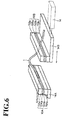
- a bend-test device for the electrical cables which are the constituents of a wire harness, according to a second embodiment of the invention.
- Fig.6 shows such a device, which comprises a pair of cable holding means 10A and 10B and a drive means 14 which brings one of the cable holding means (e.g. 10B) closer to, or farther from, the other cable holding means (e.g. 10A).
- the cable holding means 10A includes a pair of holding members 1 lAa and 11Ab generally having a rectangular form. These holding members 11Aa and 11Ab are superposed to each other, so as to hold an electrical cable 1 therebetween, and then cramped by e.g. a screw in a direction perpendicular to the cable's axis (vertical direction in Fig.6).
- a pair of elastic material portions or elastic members 12Aa and 12Ab may be provided between the above-mentioned holding members 11Aa and 11Ab, so that the electrical cable 1 is held only through these elastic material portions 12Aa and 12Ab.
- the elastic material portions may be formed of e.g. a rubber material.
- Figs.7(a) and 7(b) show how the holding members 11Aa and 11Ab seize the electrical cable 1, when they are directly applied.
- the electrical cable 1 may be compressed by a cramping force in the vertical direction in Fig.6. If the cable holding means 10B is brought closer to the other cable holding means 10A in this state, the electrical cable 1 may tend to be bent in the zone where it is compressed, i.e. where the holding members 11Aa and 11Ab are located. As a consequence, the wire core contained in the electrical cable 1 may be broken in that zone, in which case a precise bend test cannot be carried out.
- the elastic material portions 12Aa and 12Ab are mounted in a zone in contact with the electrical cable 1, which zone is interposed between the holding members 11Aa and 11Ab, the electrical cable 1 is held by the elastic deformation of these elastic material portions 12Aa and 12Ab, so that the electrical cable 1 can be efficiently prevented from the deformation due to compression.
- the electrical cable 1 is prevented from flexing in the periphery of the first cable holding means 10A.
- the median point of the electrical cable 1 thus becomes the main flexing point, and precise bend tests can be performed in a reliable way.
- the second cable holding means 10B is constructed as in the case of the first cable holding means 10A: holding members 11Ba and 11Bb are superposed, and the zone of holding members 11Ba and 11Bb where the cable 1 is in contact with the electrical cable is provided with elastic material portions or elastic members 12Ba and 12Bb.
- the first cable holding means 10A is mounted on a immobilized base 14A fixedly installed on a working bench (Fig.6).
- the second cable holding means 10B is mounted on a movable base 14B which is installed on the working bench in a freely movable way: it can be brought closer to, or farther from, the immobilized base 14A.
- the first and second cable holding means 10A and 10B include, respectively, rectangular-shaped holding members 11A and 11B.
- the first and second cable holding means 10A and 10B are then placed in such a way that these rectangular shapes are arranged in parallel relation to each other, in a direction perpendicular to the movement axis, i.e. longitudinal axis of the electrical cable. They are then brought closer to, or farther from, each other in a freely movable way.
- the movable base 14B is linked to a drive or piston means 14, which may include pneumatic ram.
- This drive means 14 gives repeated movements to the movable base 14B, by pushing it towards, and pulling it farther from, the immobilized base 14A.
- the first and second cable holding means 10A and 10B are first arranged in the farthest position from each other.
- a stretched electrical cable 1 is then held by the holding members 11Aa and 11Ab of the first cable holding means 10A on the one hand, and the holding members 11Ba and 11Bb of the second cable holding means 10B, on the other.
- the first and second cable holding means 10A and 10B are then subjected to closing and separating movements caused by the drive means 14.
- the electrical cable 1 is imparted with a buckling force in its longitudinal direction, and the median point of the cable 1 is flexed and deformed.
- the electrical cable 1 is stretched in its longitudinal direction, and deformed back. As this movement is repeated, flexing and stretching deformation of the median point is also repeated.
- the approaching-and-separating movements are repeated until the electrical cable 1 breaks or fails, and the number of the movements of second cable holding means 10B up to this break or failure point is counted.
- the bend frequencies thus obtained are defined as the lifetime of the electrical cable 1 under repeated bending.
- a conductivity-detection unit for detecting the break of the wire core of electrical cable 1, and a counting unit for counting the reciprocating movements of second cable holding means 10B, which are recorded up to the break (failure) point detected by the conductivity-detection unit.
- the holding members 11Aa and 11Ab may include a corresponding elastic material portion 12Aa and 12Ab (or 12Ba and 12Bb), which is formed of an elastic material and seizes the electrical cable 1.
- the elastic material portions 12Aa and 12Ab are elastically deformed, so that the electrical cable 1 itself can avoid the deformation due to compression. Consequently, the electrical cable 1 is prevented from flexing in proximity of the first and second cable holding means 10A and 10B. As a result, the electrical cable 1 is flexed at the median point, and the bend tests can be effected correctly.
- the bend-test device of the invention handles each electrical cable 1 individually, so that it has a much simpler structure than a bend-test device such as shown in Fig. 1, which handles a unitary wire harness.
- the inventive device thus has a compact structure better adapted to swift movements.
- the electrical cable 1 can be flexed at a rate of 5 times (cycles) per second.
- the device of Fig. 1 takes about 3 seconds for one flexing of a wire harness. Moreover, it takes 2000 to 3000 flexing cycles for a wire harness, until the last constituent electrical cable fails. Testing of a wire harness thus requires a considerable amount of time in the prior art.
- bend tests are carried out with each electrical cable constituting a wire harness separately, until the electrical cable in question fails.
- the lifetime of the wire harness is then estimated on the basis of the result obtained for each electrical cable.
- the bend tests can therefore be conducted more easily by using a compact, lightly equipped test device.
- the median point of an electrical cable located halfway between the first and second cable holding means, is imparted with a load towards a direction perpendicular to the axis of the electrical cable. Thereafter, the holding means are brought closer to each other, and brought farther from each other, so that the electrical cable is flexed and stretched reciprocatingly. In this manner, the electrical cable is flexed always in the same direction, and the bend tests give highly reliable results.
- a pair of cable holding means carrying a corresponding holding member adapted to hold an electrical cable. Both cable holding means are mounted such that they can be brought closer to each other, or farther from each other, in a freely movable way.
- a drive means for reciprocating a cable holding means are also provided.
- the holding members include, respectively, an elastic material portion for cramping the electrical cable. When the electrical cable is held, the elastic material portion is elastically strained, so that the electrical cable itself can avoid the compressive strain. Moreover, when effecting bend tests, the electrical cable is properly flexed at the median point thereof, and not at the proximity of the cable holding means.
Landscapes
- Physics & Mathematics (AREA)
- Health & Medical Sciences (AREA)
- Life Sciences & Earth Sciences (AREA)
- Chemical & Material Sciences (AREA)
- Analytical Chemistry (AREA)
- Biochemistry (AREA)
- General Health & Medical Sciences (AREA)
- General Physics & Mathematics (AREA)
- Immunology (AREA)
- Pathology (AREA)
- Investigating Strength Of Materials By Application Of Mechanical Stress (AREA)
Applications Claiming Priority (2)
| Application Number | Priority Date | Filing Date | Title |
|---|---|---|---|
| JP2000079717A JP3282619B2 (ja) | 2000-03-22 | 2000-03-22 | ワイヤーハーネスの屈曲試験方法及び電線の屈曲試験装置 |
| JP2000079717 | 2000-03-22 |
Publications (2)
| Publication Number | Publication Date |
|---|---|
| EP1136810A2 true EP1136810A2 (de) | 2001-09-26 |
| EP1136810A3 EP1136810A3 (de) | 2002-02-06 |
Family
ID=18596921
Family Applications (1)
| Application Number | Title | Priority Date | Filing Date |
|---|---|---|---|
| EP01400713A Withdrawn EP1136810A3 (de) | 2000-03-22 | 2001-03-19 | Biegeprüfung eines Kabelbaums und dafür geeignete Vorrichtung |
Country Status (3)
| Country | Link |
|---|---|
| US (1) | US6494104B2 (de) |
| EP (1) | EP1136810A3 (de) |
| JP (1) | JP3282619B2 (de) |
Cited By (3)
| Publication number | Priority date | Publication date | Assignee | Title |
|---|---|---|---|---|
| EP1209460A3 (de) * | 2000-11-21 | 2004-11-17 | Sumitomo Wiring Systems, Ltd. | Vorrichtung zum Biegungstest für ein elektrisches Kabel oder einen elektrischen Kabelbaum |
| DE102015014770A1 (de) * | 2015-11-13 | 2017-05-18 | GM Global Technology Operations LLC (n. d. Ges. d. Staates Delaware) | Verfahren zur Bestimmung elastischer Eigenschaften eines Kraftfahrzeug-Kabelbaums |
| DE102016223900A1 (de) * | 2016-12-01 | 2018-06-07 | Fraunhofer-Gesellschaft zur Förderung der angewandten Forschung e.V. | Messvorrichtung zum Vermessen des Biegeverhaltens einer Probe |
Families Citing this family (31)
| Publication number | Priority date | Publication date | Assignee | Title |
|---|---|---|---|---|
| US7041481B2 (en) | 2003-03-14 | 2006-05-09 | The Regents Of The University Of California | Chemical amplification based on fluid partitioning |
| JP4865519B2 (ja) * | 2006-12-06 | 2012-02-01 | 古河電気工業株式会社 | 電線の耐屈曲性試験装置およびその試験方法 |
| US10512910B2 (en) | 2008-09-23 | 2019-12-24 | Bio-Rad Laboratories, Inc. | Droplet-based analysis method |
| US9399215B2 (en) | 2012-04-13 | 2016-07-26 | Bio-Rad Laboratories, Inc. | Sample holder with a well having a wicking promoter |
| US9764322B2 (en) | 2008-09-23 | 2017-09-19 | Bio-Rad Laboratories, Inc. | System for generating droplets with pressure monitoring |
| US8951939B2 (en) | 2011-07-12 | 2015-02-10 | Bio-Rad Laboratories, Inc. | Digital assays with multiplexed detection of two or more targets in the same optical channel |
| US9417190B2 (en) | 2008-09-23 | 2016-08-16 | Bio-Rad Laboratories, Inc. | Calibrations and controls for droplet-based assays |
| US8709762B2 (en) | 2010-03-02 | 2014-04-29 | Bio-Rad Laboratories, Inc. | System for hot-start amplification via a multiple emulsion |
| EP4512526A3 (de) | 2008-09-23 | 2025-06-04 | Bio-Rad Laboratories, Inc. | Tropfenbasiertes assaysystem |
| US9492797B2 (en) | 2008-09-23 | 2016-11-15 | Bio-Rad Laboratories, Inc. | System for detection of spaced droplets |
| US8633015B2 (en) | 2008-09-23 | 2014-01-21 | Bio-Rad Laboratories, Inc. | Flow-based thermocycling system with thermoelectric cooler |
| US12162008B2 (en) | 2008-09-23 | 2024-12-10 | Bio-Rad Laboratories, Inc. | Partition-based method of analysis |
| US9156010B2 (en) | 2008-09-23 | 2015-10-13 | Bio-Rad Laboratories, Inc. | Droplet-based assay system |
| US12090480B2 (en) | 2008-09-23 | 2024-09-17 | Bio-Rad Laboratories, Inc. | Partition-based method of analysis |
| WO2011120020A1 (en) | 2010-03-25 | 2011-09-29 | Quantalife, Inc. | Droplet transport system for detection |
| US9132394B2 (en) | 2008-09-23 | 2015-09-15 | Bio-Rad Laboratories, Inc. | System for detection of spaced droplets |
| US8663920B2 (en) | 2011-07-29 | 2014-03-04 | Bio-Rad Laboratories, Inc. | Library characterization by digital assay |
| US11130128B2 (en) | 2008-09-23 | 2021-09-28 | Bio-Rad Laboratories, Inc. | Detection method for a target nucleic acid |
| CA2767056C (en) | 2009-09-02 | 2018-12-04 | Bio-Rad Laboratories, Inc. | System for mixing fluids by coalescence of multiple emulsions |
| US8399198B2 (en) | 2010-03-02 | 2013-03-19 | Bio-Rad Laboratories, Inc. | Assays with droplets transformed into capsules |
| JP2013524169A (ja) | 2010-03-25 | 2013-06-17 | クァンタライフ・インコーポレーテッド | 液滴によるアッセイ用の検出システム |
| CA2767182C (en) | 2010-03-25 | 2020-03-24 | Bio-Rad Laboratories, Inc. | Droplet generation for droplet-based assays |
| EP3574990B1 (de) | 2010-11-01 | 2022-04-06 | Bio-Rad Laboratories, Inc. | System zur formung von emulsionen |
| US12097495B2 (en) | 2011-02-18 | 2024-09-24 | Bio-Rad Laboratories, Inc. | Methods and compositions for detecting genetic material |
| CN103534360A (zh) | 2011-03-18 | 2014-01-22 | 伯乐生命医学产品有限公司 | 借助对信号的组合使用进行的多重数字分析 |
| EP3395957B1 (de) | 2011-04-25 | 2020-08-12 | Bio-Rad Laboratories, Inc. | Verfahren und zusammensetzungen zur nukleinsäureanalyse |
| CN103185851A (zh) * | 2011-12-30 | 2013-07-03 | 北京谊安医疗系统股份有限公司 | 柔性电缆弯折寿命试验装置 |
| CN104458434B (zh) * | 2014-12-19 | 2017-02-01 | 积架宝威汽车配件(深圳)有限公司 | 一种汽车连接线的寿命测试设备 |
| CN111504788B (zh) * | 2020-05-09 | 2023-06-06 | 安徽天大铜业有限公司 | 一种铜线弯曲后的拉力检测机构 |
| CN112414875A (zh) * | 2020-11-10 | 2021-02-26 | 天津富通光缆技术有限公司滨海新区分公司 | 一种评价蝶形光缆长轴l向弯曲性能的测试方法及装置 |
| CN118913928B (zh) * | 2024-08-16 | 2025-05-06 | 苏州波特尼电气系统有限公司 | 一种汽车线束检测装置 |
Family Cites Families (10)
| Publication number | Priority date | Publication date | Assignee | Title |
|---|---|---|---|---|
| DE873450C (de) * | 1951-05-01 | 1953-04-13 | Textilforschungsanstalt Krefel | Verfahren und Vorrichtung zum Pruefen von Geweben, Faeden od. dgl. auf Scheuerfestigkeit |
| US3871217A (en) * | 1973-04-25 | 1975-03-18 | Rucker Co | Continuous cable tension monitor |
| US4676110A (en) * | 1986-07-16 | 1987-06-30 | The United States Of America As Represented By The Administrator Of The National Aeronautics And Space Administration | Fatigue testing a plurality of test specimens and method |
| US4869111A (en) * | 1987-10-02 | 1989-09-26 | Ngk Spark Plug Co., Ltd. | Cyclic fatigue testing apparatus |
| US4979396A (en) * | 1990-02-23 | 1990-12-25 | The United States Of America As Represented By The Secretary Of The Navy | Fatigue testing apparatus |
| FR2711241B1 (fr) * | 1993-10-14 | 1995-12-29 | Marseille Labo Interreg Concur | Dispositif semi-automatique à étau oscillant pour essais de flexions des fils métalliques. |
| JPH08166333A (ja) * | 1994-10-11 | 1996-06-25 | Sumitomo Electric Ind Ltd | 複合体の耐屈曲寿命予測方法及び複合体の耐屈曲性評価方法 |
| US5677494A (en) * | 1996-03-05 | 1997-10-14 | Mcdonnell Douglas Corporation | Method for high strain-rate testing of specimens |
| US5945594A (en) * | 1998-10-14 | 1999-08-31 | Meritor Light Vehicle Systems-France | Method and apparatus for the electrochemical inspection of galvanized cable and method and apparatus for predicting the corrosion life of galvanized cable undergoing mechanical fatigue |
| EP1117105B1 (de) * | 1999-07-26 | 2005-10-19 | Sumitomo Wiring Systems, Ltd. | Verfahren zur vorhersage der biegung eines elektrischen drahtes oder elektrischen drahtbündels |
-
2000
- 2000-03-22 JP JP2000079717A patent/JP3282619B2/ja not_active Expired - Fee Related
-
2001
- 2001-03-19 EP EP01400713A patent/EP1136810A3/de not_active Withdrawn
- 2001-03-21 US US09/812,590 patent/US6494104B2/en not_active Expired - Fee Related
Non-Patent Citations (1)
| Title |
|---|
| None * |
Cited By (4)
| Publication number | Priority date | Publication date | Assignee | Title |
|---|---|---|---|---|
| EP1209460A3 (de) * | 2000-11-21 | 2004-11-17 | Sumitomo Wiring Systems, Ltd. | Vorrichtung zum Biegungstest für ein elektrisches Kabel oder einen elektrischen Kabelbaum |
| DE102015014770A1 (de) * | 2015-11-13 | 2017-05-18 | GM Global Technology Operations LLC (n. d. Ges. d. Staates Delaware) | Verfahren zur Bestimmung elastischer Eigenschaften eines Kraftfahrzeug-Kabelbaums |
| DE102016223900A1 (de) * | 2016-12-01 | 2018-06-07 | Fraunhofer-Gesellschaft zur Förderung der angewandten Forschung e.V. | Messvorrichtung zum Vermessen des Biegeverhaltens einer Probe |
| DE102016223900B4 (de) * | 2016-12-01 | 2018-12-20 | Fraunhofer-Gesellschaft zur Förderung der angewandten Forschung e.V. | Messvorrichtung zum Vermessen des Biegeverhaltens einer Probe |
Also Published As
| Publication number | Publication date |
|---|---|
| US20010029788A1 (en) | 2001-10-18 |
| JP2001266676A (ja) | 2001-09-28 |
| US6494104B2 (en) | 2002-12-17 |
| EP1136810A3 (de) | 2002-02-06 |
| JP3282619B2 (ja) | 2002-05-20 |
Similar Documents
| Publication | Publication Date | Title |
|---|---|---|
| EP1136810A2 (de) | Biegeprüfung eines Kabelbaums und dafür geeignete Vorrichtung | |
| KR101654164B1 (ko) | 통전용 시편 인장 압축 시험 장치 및 그 방법 | |
| US20020059834A1 (en) | Bend test device for an electrical cable or wire harness | |
| EP1139089A2 (de) | Vorrichtung zum Biegungstest von Kabelbäumen | |
| SK3122002A3 (en) | Terminal crimped state testing method | |
| CN111307594B (zh) | 一种板栅机械性能测试装置及测试方法 | |
| JP2013064717A (ja) | ケーブル屈曲疲労寿命予測方法、及びケーブル屈曲疲労寿命予測装置 | |
| WO2019201626A1 (de) | Überwachungssystem für den betrieb einer energieführungskette | |
| KR20220073120A (ko) | 인장강도 측정기용 고정 그리퍼 및 인장강도 측정기 | |
| CN112763412A (zh) | 材料摩擦异响试验台弹簧式蓄能机构 | |
| KR101140862B1 (ko) | 소성변형비 측정장치 | |
| JP2011111159A (ja) | 力センサーを備えるアクチュエータ装置 | |
| CN205538195U (zh) | 一种高效断路器弹簧应力松弛性能测试装置 | |
| Sawa | Correlation between nanoindentation test result and vickers hardness | |
| KR101465740B1 (ko) | 만능재료시험기 및 그 그립유닛 | |
| KR102802505B1 (ko) | 와이어의 트위스트 인장 시험기 | |
| RU2357223C1 (ru) | Способ испытаний упругих стержней на долговечность и устройство для его осуществления | |
| JPH1030980A (ja) | 衝撃試験装置 | |
| EP0692718A1 (de) | Verfahren und Gerät zur Prüfung eines elektrischen Steckers | |
| JP7519688B2 (ja) | ロープ検査装置およびロープ検査方法 | |
| KR100888672B1 (ko) | 인장 크리프 시험기용 그립 | |
| CN221302987U (zh) | 一种软管拉伸夹具及拉伸装置 | |
| CN113607548A (zh) | 一种槽道本体拉伸强度力学试验工装及其应用 | |
| Yang et al. | Threshold of axial vibration induced fretting in electrical connectors | |
| KR101401257B1 (ko) | 비정질 금속재료의 변형정도 모니터링 방법과 이를 위한 굽힘시험 방법 및 장치 |
Legal Events
| Date | Code | Title | Description |
|---|---|---|---|
| PUAI | Public reference made under article 153(3) epc to a published international application that has entered the european phase |
Free format text: ORIGINAL CODE: 0009012 |
|
| 17P | Request for examination filed |
Effective date: 20010326 |
|
| AK | Designated contracting states |
Kind code of ref document: A2 Designated state(s): AT BE CH CY DE DK ES FI FR GB GR IE IT LI LU MC NL PT SE TR Kind code of ref document: A2 Designated state(s): DE FR GB |
|
| AX | Request for extension of the european patent |
Free format text: AL;LT;LV;MK;RO;SI |
|
| PUAL | Search report despatched |
Free format text: ORIGINAL CODE: 0009013 |
|
| AK | Designated contracting states |
Kind code of ref document: A3 Designated state(s): AT BE CH CY DE DK ES FI FR GB GR IE IT LI LU MC NL PT SE TR |
|
| AX | Request for extension of the european patent |
Free format text: AL;LT;LV;MK;RO;SI |
|
| AKX | Designation fees paid |
Free format text: DE FR GB |
|
| 17Q | First examination report despatched |
Effective date: 20061128 |
|
| STAA | Information on the status of an ep patent application or granted ep patent |
Free format text: STATUS: THE APPLICATION HAS BEEN WITHDRAWN |
|
| 18W | Application withdrawn |
Effective date: 20130816 |