EP1136732A2 - Anziehanordnung für Dichtung - Google Patents
Anziehanordnung für Dichtung Download PDFInfo
- Publication number
- EP1136732A2 EP1136732A2 EP01302189A EP01302189A EP1136732A2 EP 1136732 A2 EP1136732 A2 EP 1136732A2 EP 01302189 A EP01302189 A EP 01302189A EP 01302189 A EP01302189 A EP 01302189A EP 1136732 A2 EP1136732 A2 EP 1136732A2
- Authority
- EP
- European Patent Office
- Prior art keywords
- gasket
- warp
- improvement
- limiter member
- recited
- Prior art date
- Legal status (The legal status is an assumption and is not a legal conclusion. Google has not performed a legal analysis and makes no representation as to the accuracy of the status listed.)
- Withdrawn
Links
- 238000010276 construction Methods 0.000 title claims abstract description 37
- 238000007789 sealing Methods 0.000 claims abstract description 53
- 239000000567 combustion gas Substances 0.000 claims abstract description 14
- 239000011324 bead Substances 0.000 claims description 35
- 239000002184 metal Substances 0.000 claims description 18
- 239000002131 composite material Substances 0.000 claims description 7
- 239000007769 metal material Substances 0.000 claims description 3
- 238000009877 rendering Methods 0.000 abstract description 2
- 230000013011 mating Effects 0.000 description 9
- 230000000694 effects Effects 0.000 description 5
- 230000004048 modification Effects 0.000 description 5
- 238000012986 modification Methods 0.000 description 5
- 239000002826 coolant Substances 0.000 description 4
- 239000000853 adhesive Substances 0.000 description 3
- 230000001070 adhesive effect Effects 0.000 description 3
- 230000006835 compression Effects 0.000 description 2
- 238000007906 compression Methods 0.000 description 2
- 230000009977 dual effect Effects 0.000 description 2
- 239000000463 material Substances 0.000 description 2
- 229910001220 stainless steel Inorganic materials 0.000 description 2
- 239000010935 stainless steel Substances 0.000 description 2
- 238000003466 welding Methods 0.000 description 2
- 238000002485 combustion reaction Methods 0.000 description 1
- 230000008030 elimination Effects 0.000 description 1
- 238000003379 elimination reaction Methods 0.000 description 1
- 239000000446 fuel Substances 0.000 description 1
- 239000007789 gas Substances 0.000 description 1
- 238000009434 installation Methods 0.000 description 1
- 238000000034 method Methods 0.000 description 1
- 230000001105 regulatory effect Effects 0.000 description 1
- 229920005989 resin Polymers 0.000 description 1
- 239000011347 resin Substances 0.000 description 1
Images
Classifications
-
- F—MECHANICAL ENGINEERING; LIGHTING; HEATING; WEAPONS; BLASTING
- F16—ENGINEERING ELEMENTS AND UNITS; GENERAL MEASURES FOR PRODUCING AND MAINTAINING EFFECTIVE FUNCTIONING OF MACHINES OR INSTALLATIONS; THERMAL INSULATION IN GENERAL
- F16J—PISTONS; CYLINDERS; SEALINGS
- F16J15/00—Sealings
- F16J15/02—Sealings between relatively-stationary surfaces
- F16J15/06—Sealings between relatively-stationary surfaces with solid packing compressed between sealing surfaces
- F16J15/08—Sealings between relatively-stationary surfaces with solid packing compressed between sealing surfaces with exclusively metal packing
- F16J15/0818—Flat gaskets
- F16J2015/0862—Flat gaskets with a bore ring
Definitions
- the present invention relates to a construction for squeezing a gasket disposed between confronting surfaces of engine components, for example cylinder heads, cylinder blocks and others by a clamping force that results from the tightening of fastening bolts.
- metal gaskets With metal gaskets, multi-layer gaskets are conventionally known in public, which are used placed between engine parts such as cylinder blocks, cylinder heads, and so on of automotive engines.
- An exemplification of the metal gaskets is disclosed in, for example, Japanese Patent Laid-Open No. 39868/1993.
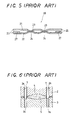
- a prior metal gasket 20 shown in FIGS. 4 and 5 is comprised of a pair of bead sheets 21, 22 of stainless steel overlaid one on the other, each of which is made with beads 23, 214 extending around holes 25 formed in alignment with cylinder bores.
- the metal gasket 20 is a head gasket designed for multi-cylinder engine, and thus the bead sheets 21, 22 are each provided therein with holes 25 arranged juxtaposed in conformation with cylinder bores in the cylinder block of the engine.
- the bead sheets 21, 22 are also made with bolt holes 26 through which head bolts extend to clamp together the cylinder head and the cylinder block, and other holes for coolant, oil, and so on.
- the bead sheets 21, 22 of the metal gasket 20, as shown in FIG. 5, are made with the beads 23, 24 of full bead type, which are raised above any one face thereof towards each other so as to make line abutment against each other at the beads in a cross section taken on the plane joining the centers of any adjacent holes 25.
- any one dead sheets, or bead sheet 22 has a flange 22 formed by folding back the bead sheet itself at a return defining the associated hole 25 to be overlaid on the major surface of the bead sheet, with extending radially to the extent of not having to interfere with the associated bead 24.
- each bead 23, 24 is formed independently of one another at an area between any two adjacent holes 25, it will be appreciated that the adjoining beads 23, 24 may be made to merge into a single bead. Moreover, it is wellknown that the modification in width and/or height of the beads 23, 24 and in thickness and/or width of the flanges 27 results in the increase of compressive sealing stress when tightened, at the area between the adjacent holes 25, which extends over an angle ⁇ shown in FIG. 4.
- the beads 23, 24 When tightening the head bolts to squeeze the metal gasket 20 placed between the confronting surfaces of the engine components, the beads 23, 24 generates, in combination with the flange 27 folded back to serve increasing the sheet thickness, a dual annular sealing construction of high compressive sealing stress around the associated hole 25.
- the dual annular sealing construction prevents leakage combustion gases through the joint between the mating surfaces of the engine components.
- the head gasket has areas where the gasket is jointed together with the cylinder head, or bolt holes 26 in which the head bolts are installed to tighten together the cylinder head and the cylinder block.
- the bolt holes 26 are arranged in only the perimetral area of the metal gasket 20 due to spatial design restrictions and further, not all the bolt holes 26 are uniformly disposed around the holes at areas where the sealing effects are need locally.
- the compressive sealing stress desired in the head gasket 20 differs in magnitude between a first sealing stress level needed at areas around the holes 25 and a second sealing stress desired neighboring the coolant holes and oil holes. It will be understood that the first sealing stress is set higher than the second sealing stress.
- the metal gaskets for the current engines are involved inherently with the antinomic subject matter: it is needed to render the spring constant of the bead large to reduce the warp at the mating surfaces by either the use of materials higher in elasticity and/or stiffness or the modification embodied in the gasket construction, while the elastic effect should be regulated such that the sealing stress does not converge on only any local area, but diverges uniformly over the gasket. Nevertheless, the above-mentioned vicious relation between the gasket construction and the sealing stress on the sealing areas is considered a major problem left to solve, compared with the antinomic subject matter described just above.
- a squeezing construction for a gasket disposed between the confronting surfaces of the engine components such as cylinder head, cylinder block, and so on, in which a clamping force resulting from the tightening of fastening bolts to squeeze together the gasket between the confronting surfaces is made uniform throughout the entire of the gasket while a sealing stress created neighboring bolt holes where the fastening bolts are inserted is made as even as possible to realize the sealing stress uniformed throughout around a combustion hole whereby a warp, otherwise might occur on the mating surfaces to be sealed, is made less and also reduced in variation.
- a primary aim of the present invention is to overcome the major problem stated earlier and in particular provide a squeezing construction for a gasket disposed between confronting surfaces of the engine components such as cylinder head, cylinder block, and so on, which makes it possible to avoid a phenomenon an axial fastening force exerted to a fastening bolt becomes high only at some limited fastening bolts, thereby keeping the axial tightening force down on all fastening bolts to suppress any warp, which might occur in the confronting surfaces.
- the gaskets are improved in the sealing performance, durability and reliability at the joints of the mating surfaces of the confronting engine components, thus helping improve fuel consumption and purify the exhaust gases.
- the present invention is concerned with a squeezing construction for a gasket, in which the gasket is placed between confronting surfaces of engine components made therein with combustion gas holes and arranged in opposition to each other, and squeezed by tightening a fastening bolt to seal a joint between the confronting surfaces of engine components, and wherein a warp-limiter member is installed in a bolt hole formed in the gasket, in which the fastening bolt fits, the warp-limiter member being made tougher to flex than the confronting surfaces of the components, to which the warp-limiter member comes in abutment.
- the warp-limiter member fits in the bolt hole, which is made less in an amount of flex or warp than the confronting surfaces of the engine components under the clamping force.
- the amount of flex arising from the clamping force is not equivalent with only the amount of flex occurring in the engine components mating directly with the gasket, but taken up partially by the thickness of the warp-limiter member, which is high in elasticity and correspondingly less in the amount of flex.
- the clearance between the confronting surfaces of the engine components can be adjusted easily by virtue of the thickness of the warp-limiter member, so that it becomes easy to control the axial fastening force applied to the fastening bolt, which has the great effects on the amount of flex occurring in the engine components.
- This consequently, makes it possible to bypass the phenomenon such that the axial fastening force and the corresponding amount of axial flex increases at only some limited fastening bolts.
- the warp-limiter member serves to suppress the axial fastening force of the fastening bolt and the amount of flex arising from the axial fastening force as uniformly as possible, thereby rendering variation in distortion in the sealing joint less to improve the sealing performance.
- an improvement in a squeezing construction for a gasket wherein the engine components are a cylinder block and a cylinder head to be jointed with cylinder block, and the gasket is disposed between the confronting surfaces of the cylinder head and the cylinder block.
- an improvement in a squeezing construction for a gasket wherein the engine components are a cylinder head and any one of an intake manifold and an exhaust manifold to be jointed with the cylinder head, and the gasket is disposed between confronting surfaces of the cylinder head and any one of the intake manifold and the exhaust manifold.
- an improvement in a squeezing construction for a gasket wherein the gasket is composed of any one selected from a metallic gasket of one metallic sheet or layered metallic sheets, a resinous gasket of resinous sheet, and a composite gasket of the at least one metallic sheet and the resinous sheet.
- an improvement in a squeezing construction for a gasket wherein the warp-limiter members are installed in all the bolt holes, one to each bolt hole.
- an improvement in a squeezing construction for a gasket wherein the warp-limiter member has a thickness that is preselected so as to ensure a desired sealing stress made uniform in the gasket around the combustion gas holes when the fastening bolt is turned through a preselected specified angle where the fastening bolt is tightened to such extent that the final tightening of the fastening bolt reaches a preselected amount or length of tightening.
- an improvement in a squeezing construction for a gasket wherein the warp-limiter member is installed in the bolt hole, rather than attached to the gasket.
- the warp-limiter member may be installed in the bolt hole with attached to the gasket through securing means such as adhesive, welding, engagement, and so on. That is to say, the warp-limiter member may be formed in either an independent part separated absolutely from the gasket or a part integral with the gasket.
- an improvement in a squeezing construction for a gasket wherein the warp-limiter member is made of any one selected from a single hard metal plate, layered metal sheet, sintered metallic substances and composite materials, which is formed in a washer-like shape allowing the fastening bolt to extend through there.
- an improvement in a squeezing construction for a gasket wherein the gasket is made therein with a combustion gas hole in alignment with the combustion gas holes in the engine components, and further provided with a bead surrounding around the combustion gas hole.
- the warp-limiter member is installed in the bolt hole, which is made of a washer, layered metallic plate, and so on rendered less in the amount of flex than the engine components.
- the warp-limiter member is allowed to vary in thickness as far as the beads and folded flanges may serve their functions.
- the cylinder head and the cylinder block are less subject to distortion when turning each fastening bolt through the specified angle.
- the sealing stress at the joints may be made much more uniformed.
- the axial fastening force set according to the lowest sealing stress standard can be also made reduced.
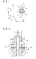
- a gasket 1 in FIG. 1 is a head gasket used in a manner shown in FIG. 2, which is disposed under squeezed condition between confronting surfaces 4, 5 of engine components: a cylinder head 2 and a cylinder block 3 to seal the joint between the confronting surfaces 4, 5.
- the gasket 1 shown in FIG. 1, as with the prior metallic gasket in FIGS. 5 and 6, may be made of metallic sheets overlaid one on the other, and designed for multi-cylinder engines such as four- or six-cylinder engines.
- the gasket 1, except a construction at an area around a bolt hole in which a tightening bolt fits, is principally identical in construction with the gasket 20 stated earlier. To that extent, like components have been given the same reference characters, so that the previous description will be applicable.
- a metallic sheet 10 of the gasket 1 is provided therein with holes 25 arranged juxtaposed in alignment cylinder bores in the cylinder block 3. Moreover, the metallic sheet 10 is made with bolt holes 15 in which fastening bolts 7 fit to keep in place both the cylinder head 2 and the cylinder block 3 and squeeze the gasket 1 between the confronting cylinder head 2 and cylinder block 3. Although the metallic sheet 10 is also made with other various holes such as coolant holes, oil holes knock holes, and so on, these holes are well known to those skilled in the art, and thus the detailed description thereof will be omitted herein.
- FIG. 1 shows in plan view a bolt hole 15 and a nearby area around the bolt hole 15, while FIG. 2 is a section taken on a plane I - I of FIG. 1.
- the gasket 1 as seen in section of FIG. 2, is raised around the bolt hole 15 above any one surface of a major sheet area 11 of the gasket 1 to form a half bead 12, which has an inside end defining a perimetral edge 13 encircling the bolt hole 15.
- the bolt hole 15 is made in an opening diameter Da larger than a bolt diameter Dc of the fastening bolt 7 to provide an annular space between the perimetral edge 13 of the bolt hole 15 and an outside periphery of the fastening bolt 7.
- a warp-limiter member 17 Arranged in the annular space is a warp-limiter member 17 stated later.
- the warp-limiter member 17 as a whole is formed in an annular shape, in which an inside periphery 18 of the warp-limiter member 17 is determined to have a diameter substantially equal with the bolt diameter Dc of the fastening bolt 7 to the extent allowing the fastening bolt 7 to pass through there.
- the warp-limiter member 17 is also made in an outside diameter Db somewhat smaller than the opening diameter Da of the bolt hole 15 to isolate the warp-limiter member 17 from the perimetral edge 13 of the half bead 12 with a small clearance between them.
- an appropriate adhesive such as resins and so on is charged into an annular clearance between the warp-limiter member 17 and the perimetral edge 13 of the gasket 1.
- the warp-limiter member 17 may be anchored with adhesion means such as welding, riveting, adhesive, and so on through at least three fingers 19, as shown in FIG. 1, which are arranged circumferentially along the perimetral edge 13 of the gasket 1.
- the warp-limiter member 17 is made of, but is not limited to, for example a stainless steel plate made in a washer or a clad metal plate, which is less subject to warp than the engine components such as the cylinder head 2 and cylinder block 3.
- the warp-limiter member 17 is set tougher to flex under the same stress than the confronting surfaces of the cylinder head 2 and the cylinder block 3.
- the warp-limiter members 17 are disposed in all the bolt holes 15, one to each bolt hole.
- the sealing effect at the beads 23, 24 formed around the holes 25 is not possible when using the warp-limiter member 17 excessive in the thickness Tw.
- the thickness Tw of the warp-limiter member 17 has to be determined, depending on previous findings about how best to serve the sealing performance of the beads 23, 24 and the folded flange 25, shown in FIG.
- the gasket 1 On head gasket installation, the gasket 1 is first disposed between the confronting surfaces of the cylinder head 2 and the cylinder block 3.
- the warp-limiter member 17 is subject to compressive deformation due to the elasticity in itself while the half bead 12 is pressed together with the confronting surfaces 3, 5 of the cylinder head 2 and the cylinder block 3 to be collapsed around the bolt hole 15, so that the sealing stress rises around the bolt hole 15.
- the clamping force that results from the tightening of the fastening bolt 7 reaches the areas neighboring the holes 25 in the gasket 1 to deform the beads 23, 24 formed around the holes 25, thereby realizing annular sealing zones of highly compressive sealing stress. This prevents leakage of high-temperature, high-pressure combustion gases from the joint between the cylinder head 2 and the cylinder block 3 around the holes 25.
- the warp-limiter member 17 is made of the washer or clad metal plate, which is tougher to warp than the engine components such as the cylinder head 2 and cylinder block 3. Accordingly, the warp-limiter member 17 is less subject to flex than the confronting surfaces of the cylinder head 2 and the cylinder block 3 when the gasket 1 is squeezed between the mating surfaces 4, 5 of the confronting cylinder head 2 and the cylinder block 3.
- the warp-limiter member 17 serves to reduce the distortion occurring in the cylinder head 2 and the cylinder block 3, making it possible to uniformly disperse the sealing stress, especially, throughout around the associated hole 25.
- the warp-limiter members 17 are installed in all the bolt holes 15, one to each bolt hole, the even uniformity in the sealing stress can be realized at all areas neighboring the bolt holes 25 in the gasket 1.
- the fastening bolts 7 are turned in a proper sequence through a specified angle to the specified final torque, or threshold torque where the fastening bolt is tightened to such that the final tightening of the fastening bolt reaches a preselected amount or length of tightening.
- the fastening torque exerted on the fastening bolt 7 is limited uniformly to the lowest desired force to create the sealing stress in every fastening bolt 7, there is no fear of such troublesome condition that the clamping force resulting from only some limited fastening bolts 7 becomes either too much or too little. Moreover, the axial fastening force set according to the lowest sealing stress standard can be also made reduced.
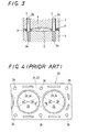
- FIG. 3 shows schematically the confronting surfaces 4, 5 of the cylinder head 2 and the cylinder block 3, which are tightened to the specified final torque by turning the fastening bolts through the specified angle in the squeezing construction for the gaskets according to the present invention.
- the amount of distortion of the confronting surfaces 4, 5 of the cylinder head 2 and the cylinder block 3 at the area spanning between the two adjacent fastening bolts 7 in FIG. 3 can be suppressed to less than or equal to a half as much as the amount of distortion of the confronting surfaces 4, 5 in FIG. 6 by virtue of the warp-limiter member 17 employed in the squeezing construction for gaskets according to the present invention.
- the squeezing construction of the present invention is not limited to use in the head gaskets: it may of course be applied with equal utility to any gasket with no limitation as to how the gasket is applied, kinds, materials, constitutions and constructions, for example to the gasket used installed between the cylinder head and the intake and exhaust system such as the intake or exhaust manifolds.
- the warp-limiter member aside from characterized by the amount of flex, is not limited in shape to washer type, and also may be made of any selected from a single hard metal plate, layered metal sheet, composite materials, sintered metallic substances.
- the warp-limiter member is allowed to vary in thickness as far as the gasket serves the sealing performance of the beads, and also the compression stopper and sealing functions of the thickened area, with keeping the sealing areas at the desired sealing stress.
- the warp-limiter member may be either formed in a part separated completely from the gasket or united previously with the gasket.
Landscapes
- Engineering & Computer Science (AREA)
- General Engineering & Computer Science (AREA)
- Mechanical Engineering (AREA)
- Gasket Seals (AREA)
Applications Claiming Priority (2)
| Application Number | Priority Date | Filing Date | Title |
|---|---|---|---|
| JP2000083433 | 2000-03-24 | ||
| JP2000083433A JP2001271935A (ja) | 2000-03-24 | 2000-03-24 | ガスケットの締付け構造 |
Publications (2)
| Publication Number | Publication Date |
|---|---|
| EP1136732A2 true EP1136732A2 (de) | 2001-09-26 |
| EP1136732A3 EP1136732A3 (de) | 2003-10-01 |
Family
ID=18600073
Family Applications (1)
| Application Number | Title | Priority Date | Filing Date |
|---|---|---|---|
| EP01302189A Withdrawn EP1136732A3 (de) | 2000-03-24 | 2001-03-09 | Anziehanordnung für Dichtung |
Country Status (3)
| Country | Link |
|---|---|
| US (1) | US6502829B2 (de) |
| EP (1) | EP1136732A3 (de) |
| JP (1) | JP2001271935A (de) |
Cited By (2)
| Publication number | Priority date | Publication date | Assignee | Title |
|---|---|---|---|---|
| US6974137B2 (en) | 2002-12-13 | 2005-12-13 | Elringklinger Ag | Flat gasket, in particular exhaust manifold gasket, and assembly accommodating such a gasket |
| CN108274798A (zh) * | 2017-12-09 | 2018-07-13 | 惠州市人防防护设备有限公司 | 一种人防专用羊毛垫圈加工设备 |
Families Citing this family (14)
| Publication number | Priority date | Publication date | Assignee | Title |
|---|---|---|---|---|
| ATE298854T1 (de) * | 2001-07-23 | 2005-07-15 | Meillor Sa | Zylinderkopfdichtung mit einem kante-zu-kante- anschlagsring |
| US20060086765A1 (en) * | 2004-10-27 | 2006-04-27 | Sportrack Llc | Sealing member for attachment components |
| WO2008128785A1 (en) * | 2007-04-24 | 2008-10-30 | Reinz-Dichtungs-Gmbh | Metallic flat gasket |
| US9447882B2 (en) * | 2008-04-17 | 2016-09-20 | Parker-Hannifin Corporation | Compression-limited gasket construction |
| WO2009152815A1 (de) * | 2008-06-21 | 2009-12-23 | Federal-Mogul Sealing Systems Gmbh | Flachdichtung |
| KR101674632B1 (ko) * | 2009-06-24 | 2016-11-09 | 페더럴-모걸 코오포레이숀 | 실린더 헤드 가스킷 |
| JP5697517B2 (ja) * | 2011-04-04 | 2015-04-08 | ニチアス株式会社 | ガスケット |
| US20140131954A1 (en) * | 2012-11-12 | 2014-05-15 | Vetco Gray Inc. | Shrinkage compensated seal assembly and related methods |
| US9638089B2 (en) * | 2014-01-23 | 2017-05-02 | Dana Automotive Systems Group, Llc | Gasket assembly |
| CN106015568B (zh) * | 2016-07-28 | 2018-08-31 | 兰州兰石集团有限公司 | 一种无螺栓密封结构 |
| US10514005B2 (en) * | 2017-02-24 | 2019-12-24 | Unison Industries, Llc | Turbine engine thermal seal |
| EP3885566A4 (de) * | 2019-03-25 | 2022-08-10 | NOK Corporation | Dichtung |
| CN114058823A (zh) * | 2021-11-29 | 2022-02-18 | 山西柴油机工业有限责任公司 | 大功率柴油机气缸垫热处理方法及回火用夹具 |
| JP7721191B1 (ja) * | 2024-11-27 | 2025-08-12 | 片山チエン株式会社 | カップリング構造 |
Family Cites Families (16)
| Publication number | Priority date | Publication date | Assignee | Title |
|---|---|---|---|---|
| FR2032044A5 (de) * | 1969-02-17 | 1970-11-20 | Cefilac | |
| US3986721A (en) * | 1975-08-08 | 1976-10-19 | Eagle-Picher Industries, Inc. | Two component gasket and method of making it |
| US4204691A (en) * | 1978-07-17 | 1980-05-27 | Toyota Jidosha Kogyo Kabushiki Kaisha | Break preventing gasket |
| DE3169936D1 (en) * | 1981-02-13 | 1985-05-23 | Freudenberg Carl Fa | Self-sealing washer |
| US4535996A (en) * | 1985-01-18 | 1985-08-20 | Felt Products Mfg. Co. | Gasket assembly for oil pans and the like and method of making same |
| US4655463A (en) * | 1986-09-05 | 1987-04-07 | Felt Products Mfg. Co. | Gasket assembly for oil pan valve covers and the like |
| US5054793A (en) * | 1988-10-11 | 1991-10-08 | Brunswick Corporation | Resilient gasket with spacers |
| JPH0717884Y2 (ja) * | 1990-10-25 | 1995-04-26 | 石川ガスケット株式会社 | ガスケット仮止め装置 |
| US5121932A (en) * | 1990-11-07 | 1992-06-16 | Fel-Pro Incorporated | Gasket assembly for oil pans and the like |
| JP2844500B2 (ja) | 1991-08-01 | 1999-01-06 | 日本ガスケット株式会社 | 金属製ガスケット |
| US5375856A (en) * | 1992-01-22 | 1994-12-27 | Ishikawa Gasket Co., Ltd. | Protecting member for a gasket |
| US5492343A (en) * | 1994-03-04 | 1996-02-20 | Federal-Mogul Corporation | Gasket assembly |
| US5536023A (en) * | 1994-10-31 | 1996-07-16 | Indian Head Industries, Inc. | One piece gasket for complex oil pan configuration |
| US5513603A (en) * | 1995-08-11 | 1996-05-07 | Chrysler Corporation | Seal and fastener isolator system for a valve cover |
| EP0775856A1 (de) * | 1995-11-23 | 1997-05-28 | TAKO PAYEN S.p.a. | Abgasrohrdichtung für Verbrennungsgase |
| US5979906A (en) * | 1997-02-13 | 1999-11-09 | Farnam/Meillor Sealing Systems Inc. | Multi-layered metal gasket assembly and method of constructing the same |
-
2000
- 2000-03-24 JP JP2000083433A patent/JP2001271935A/ja active Pending
-
2001
- 2001-03-07 US US09/799,695 patent/US6502829B2/en not_active Expired - Fee Related
- 2001-03-09 EP EP01302189A patent/EP1136732A3/de not_active Withdrawn
Cited By (2)
| Publication number | Priority date | Publication date | Assignee | Title |
|---|---|---|---|---|
| US6974137B2 (en) | 2002-12-13 | 2005-12-13 | Elringklinger Ag | Flat gasket, in particular exhaust manifold gasket, and assembly accommodating such a gasket |
| CN108274798A (zh) * | 2017-12-09 | 2018-07-13 | 惠州市人防防护设备有限公司 | 一种人防专用羊毛垫圈加工设备 |
Also Published As
| Publication number | Publication date |
|---|---|
| US20010024019A1 (en) | 2001-09-27 |
| JP2001271935A (ja) | 2001-10-05 |
| US6502829B2 (en) | 2003-01-07 |
| EP1136732A3 (de) | 2003-10-01 |
Similar Documents
| Publication | Publication Date | Title |
|---|---|---|
| US6502829B2 (en) | Gasket-squeeze construction | |
| US6575473B2 (en) | Metallic gasket | |
| EP0533357B1 (de) | Metalldichtung | |
| US8556271B2 (en) | Multilayer metal gasket | |
| US5890719A (en) | Combination metal and elastomer cylinder head gasket | |
| US6619666B1 (en) | Metal gasket assembly | |
| US6076833A (en) | Metal gasket | |
| US5876038A (en) | Metallic cylinder head gasket | |
| US6027124A (en) | Metal gasket | |
| US6457724B2 (en) | Metallic gasket | |
| US6588765B2 (en) | Monolayer metal gaskets | |
| US6206381B1 (en) | Multi-layer metal gasket | |
| US6164662A (en) | Metal gasket | |
| US5879011A (en) | Laminated metal gasket for a cylinder block of an engine | |
| CA2243916C (en) | Multi-layered cylinder head gasket with compensating intermediate plate | |
| US6969072B2 (en) | Cylinder head gasket with fold-over stopper | |
| JP3118043B2 (ja) | 金属ガスケット | |
| JP5636579B2 (ja) | ガスケット | |
| JPS63246571A (ja) | 積層金属ガスケツト | |
| JP2930779B2 (ja) | 金属製ガスケット | |
| JP2990291B2 (ja) | シリンダヘッドガスケット | |
| JPH08114266A (ja) | 金属ガスケット | |
| JP3086008B2 (ja) | 金属製ガスケット | |
| JPH0417881Y2 (de) | ||
| JP3467062B2 (ja) | メタルガスケット |
Legal Events
| Date | Code | Title | Description |
|---|---|---|---|
| PUAI | Public reference made under article 153(3) epc to a published international application that has entered the european phase |
Free format text: ORIGINAL CODE: 0009012 |
|
| AK | Designated contracting states |
Kind code of ref document: A2 Designated state(s): AT BE CH CY DE DK ES FI FR GB GR IE IT LI LU MC NL PT SE TR |
|
| AX | Request for extension of the european patent |
Free format text: AL;LT;LV;MK;RO;SI |
|
| PUAL | Search report despatched |
Free format text: ORIGINAL CODE: 0009013 |
|
| AK | Designated contracting states |
Kind code of ref document: A3 Designated state(s): AT BE CH CY DE DK ES FI FR GB GR IE IT LI LU MC NL PT SE TR |
|
| AX | Request for extension of the european patent |
Extension state: AL LT LV MK RO SI |
|
| RIC1 | Information provided on ipc code assigned before grant |
Ipc: 7F 02F 11/00 B Ipc: 7F 16J 15/12 B Ipc: 7F 16J 15/08 A |
|
| 17P | Request for examination filed |
Effective date: 20031218 |
|
| 17Q | First examination report despatched |
Effective date: 20040414 |
|
| AKX | Designation fees paid |
Designated state(s): DE GB |
|
| STAA | Information on the status of an ep patent application or granted ep patent |
Free format text: STATUS: THE APPLICATION IS DEEMED TO BE WITHDRAWN |
|
| 18D | Application deemed to be withdrawn |
Effective date: 20040825 |