EP1136689A2 - Device for supplying fuel - Google Patents
Device for supplying fuel Download PDFInfo
- Publication number
- EP1136689A2 EP1136689A2 EP01104331A EP01104331A EP1136689A2 EP 1136689 A2 EP1136689 A2 EP 1136689A2 EP 01104331 A EP01104331 A EP 01104331A EP 01104331 A EP01104331 A EP 01104331A EP 1136689 A2 EP1136689 A2 EP 1136689A2
- Authority
- EP
- European Patent Office
- Prior art keywords
- fuel
- conveying device
- fuel filter
- bypass line
- line
- Prior art date
- Legal status (The legal status is an assumption and is not a legal conclusion. Google has not performed a legal analysis and makes no representation as to the accuracy of the status listed.)
- Granted
Links
Images

Classifications
-
- F—MECHANICAL ENGINEERING; LIGHTING; HEATING; WEAPONS; BLASTING
- F02—COMBUSTION ENGINES; HOT-GAS OR COMBUSTION-PRODUCT ENGINE PLANTS
- F02M—SUPPLYING COMBUSTION ENGINES IN GENERAL WITH COMBUSTIBLE MIXTURES OR CONSTITUENTS THEREOF
- F02M37/00—Apparatus or systems for feeding liquid fuel from storage containers to carburettors or fuel-injection apparatus; Arrangements for purifying liquid fuel specially adapted for, or arranged on, internal-combustion engines
- F02M37/0011—Constructional details; Manufacturing or assembly of elements of fuel systems; Materials therefor
- F02M37/0023—Valves in the fuel supply and return system
-
- F—MECHANICAL ENGINEERING; LIGHTING; HEATING; WEAPONS; BLASTING
- F02—COMBUSTION ENGINES; HOT-GAS OR COMBUSTION-PRODUCT ENGINE PLANTS
- F02M—SUPPLYING COMBUSTION ENGINES IN GENERAL WITH COMBUSTIBLE MIXTURES OR CONSTITUENTS THEREOF
- F02M37/00—Apparatus or systems for feeding liquid fuel from storage containers to carburettors or fuel-injection apparatus; Arrangements for purifying liquid fuel specially adapted for, or arranged on, internal-combustion engines
- F02M37/0047—Layout or arrangement of systems for feeding fuel
-
- F—MECHANICAL ENGINEERING; LIGHTING; HEATING; WEAPONS; BLASTING
- F02—COMBUSTION ENGINES; HOT-GAS OR COMBUSTION-PRODUCT ENGINE PLANTS
- F02M—SUPPLYING COMBUSTION ENGINES IN GENERAL WITH COMBUSTIBLE MIXTURES OR CONSTITUENTS THEREOF
- F02M37/00—Apparatus or systems for feeding liquid fuel from storage containers to carburettors or fuel-injection apparatus; Arrangements for purifying liquid fuel specially adapted for, or arranged on, internal-combustion engines
- F02M37/22—Arrangements for purifying liquid fuel specially adapted for, or arranged on, internal-combustion engines, e.g. arrangements in the feeding system
- F02M37/32—Arrangements for purifying liquid fuel specially adapted for, or arranged on, internal-combustion engines, e.g. arrangements in the feeding system characterised by filters or filter arrangements
- F02M37/36—Arrangements for purifying liquid fuel specially adapted for, or arranged on, internal-combustion engines, e.g. arrangements in the feeding system characterised by filters or filter arrangements with bypass means
-
- F—MECHANICAL ENGINEERING; LIGHTING; HEATING; WEAPONS; BLASTING
- F02—COMBUSTION ENGINES; HOT-GAS OR COMBUSTION-PRODUCT ENGINE PLANTS
- F02M—SUPPLYING COMBUSTION ENGINES IN GENERAL WITH COMBUSTIBLE MIXTURES OR CONSTITUENTS THEREOF
- F02M37/00—Apparatus or systems for feeding liquid fuel from storage containers to carburettors or fuel-injection apparatus; Arrangements for purifying liquid fuel specially adapted for, or arranged on, internal-combustion engines
- F02M37/22—Arrangements for purifying liquid fuel specially adapted for, or arranged on, internal-combustion engines, e.g. arrangements in the feeding system
- F02M37/32—Arrangements for purifying liquid fuel specially adapted for, or arranged on, internal-combustion engines, e.g. arrangements in the feeding system characterised by filters or filter arrangements
- F02M37/50—Filters arranged in or on fuel tanks
-
- F—MECHANICAL ENGINEERING; LIGHTING; HEATING; WEAPONS; BLASTING
- F02—COMBUSTION ENGINES; HOT-GAS OR COMBUSTION-PRODUCT ENGINE PLANTS
- F02M—SUPPLYING COMBUSTION ENGINES IN GENERAL WITH COMBUSTIBLE MIXTURES OR CONSTITUENTS THEREOF
- F02M37/00—Apparatus or systems for feeding liquid fuel from storage containers to carburettors or fuel-injection apparatus; Arrangements for purifying liquid fuel specially adapted for, or arranged on, internal-combustion engines
- F02M37/0076—Details of the fuel feeding system related to the fuel tank
- F02M37/0082—Devices inside the fuel tank other than fuel pumps or filters
-
- F—MECHANICAL ENGINEERING; LIGHTING; HEATING; WEAPONS; BLASTING
- F02—COMBUSTION ENGINES; HOT-GAS OR COMBUSTION-PRODUCT ENGINE PLANTS
- F02M—SUPPLYING COMBUSTION ENGINES IN GENERAL WITH COMBUSTIBLE MIXTURES OR CONSTITUENTS THEREOF
- F02M37/00—Apparatus or systems for feeding liquid fuel from storage containers to carburettors or fuel-injection apparatus; Arrangements for purifying liquid fuel specially adapted for, or arranged on, internal-combustion engines
- F02M37/04—Feeding by means of driven pumps
- F02M37/08—Feeding by means of driven pumps electrically driven
- F02M37/10—Feeding by means of driven pumps electrically driven submerged in fuel, e.g. in reservoir
-
- Y—GENERAL TAGGING OF NEW TECHNOLOGICAL DEVELOPMENTS; GENERAL TAGGING OF CROSS-SECTIONAL TECHNOLOGIES SPANNING OVER SEVERAL SECTIONS OF THE IPC; TECHNICAL SUBJECTS COVERED BY FORMER USPC CROSS-REFERENCE ART COLLECTIONS [XRACs] AND DIGESTS
- Y10—TECHNICAL SUBJECTS COVERED BY FORMER USPC
- Y10T—TECHNICAL SUBJECTS COVERED BY FORMER US CLASSIFICATION
- Y10T137/00—Fluid handling
- Y10T137/8158—With indicator, register, recorder, alarm or inspection means
- Y10T137/8326—Fluid pressure responsive indicator, recorder or alarm
Definitions
- the invention relates to a conveyor for conveying of fuel from a fuel tank to one Internal combustion engine of a motor vehicle with a feed pump and with one connected to the feed pump Flow line and with one arranged in the flow line Fuel filter.
- Such conveyors are used in today's motor vehicles frequently used and are known from practice.
- the fuel filter to reduce one Escape of fuel into the environment within the Fuel tank arranged.
- the fuel filter must therefore have a service opening in the fuel tank be opened. Through the service opening and the seal escapes from the fuel tank however, a large amount of fuel in the area.
- the invention is based on the problem of a conveyor of the type mentioned in such a way that a promotion of fuel after adding the Fuel filter reliably secured with dirt and that there is an escape of fuel into the environment largely prevented.
- the fuel bypassed the fuel filter can be according to another advantageous development simply filter the invention when in the bypass line a second fuel filter is arranged.
- the number of sealing points on the outside of the fuel tank can be advantageous according to another Keep further development of the invention particularly low, if the bypass line and that through the fuel filter leading area of the supply line within the fuel tank are merged.
- the outside of the fuel tank another Position the fuel filter if the bypass line and the area of the supply line leading through the fuel filter one connection on the outside of each Have fuel tank and if the bypass line has a blind closure.
- the means for closing and releasing the bypass line are designed according to another advantageous Further development of the invention is particularly simple in construction, if they have a changeover valve arranged in the supply line exhibit.
- the changeover valve can be operated manually, for example if there is no fuel supply.
- the control of the means for locking and releasing the bypass line requires a particularly low one construction effort if the means to close and Release the bypass line from the pressure upstream of the fuel filter are controllable.
- the changeover valve is designed according to another one advantageous development of the invention is particularly constructive easy if it's a longitudinally slidable Has closing body.
- the switching valve can be controlled manually, for example or electrically controlled.
- the control of the changeover valve however requires according to another advantageous development of the invention a particularly little effort if the movement of the closing body in Dependency of the pressure of the feed pump is controllable.
- the switch valve can be advantageous according to another Development of the invention with particularly little Control construction costs electrically or manually, if the changeover valve has a rotatable closing body.
- Figure 1 shows an upper portion of a fuel tank 1 with a conveyor 2.
- the conveyor 2 has a feed pump 3 for conveying Fuel into an internal combustion engine, not shown leading flow line 4.
- the lead pipe 4 penetrates one inserted into an assembly opening 5 Flange 6.
- Inside the flow line 4 is a fuel filter 7 is arranged.
- the fuel filter 7 is parallel to one to one on the outside of the Flange 6 located blind closure 8 guided bypass line 9 arranged.
- FIG. 2 shows a conveyor 11, in which in the around the first fuel filter 7 bypass line 9 a second fuel filter 12 is arranged. Seen in the flow direction after the fuel filters 7, 12 is a switching valve 13 which is optional one or the other fuel filter 7, 12 with the area outside the fuel tank the flow line 4 connects. This allows clogging the first fuel filter 7, the switching valve 13 can be controlled so that the second Fuel filter 12 is flowed through with fuel.
- Figure 3 shows a conveyor 14 in which a changeover valve 15 seen in the flow direction before Fuel filter 7 is arranged.
- the Switching valve can optionally fuel over the Fuel filter 7 or through the bypass line 16 through direct a second fuel filter 17.
- the second fuel filter 17 can initially be omitted and this only after switching the switching valve 15 in the outside of the fuel tank 1 Mount the area of the flow line 4.
- the conveyor 14 can also Provide multiple switching valves, not shown, and two or more bypass lines with or without arranged therein Have fuel filters.
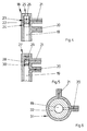
- FIG. 4 shows a changeover valve 18 as it is in the conveying devices 11, 14 used according to Figures 2 and 3 can be.
- the switching valve 18 has one with the feed pump 3 shown in FIGS. 2 and 3 connected port 19, one to the first fuel filter 7 leading connector 20 and a connector 21 for the bypass line 9, 16.
- a closing body 22 is longitudinally movable arranged, which is the terminal 21 of the bypass line 9, 16 can optionally lock or release.
- the closing body 22 has an external thread 23 and is in an internal thread 24 of the connection 19 of the feed pump 3 screwed in. Through an opening 25 is a slot 26 of the closing body 22 for attaching a not shown Turning tool accessible.
- Figure 5 shows a changeover valve 27, as it is in the conveyor 14 from Figure 3 can be used.
- the connection can be made 21 of the bypass line 16 from a longitudinally movable Release or close the closing body 28.
- the pressure in the connection increases 19 of the feed pump 3.
- the closing body 28 will then by the pressure of the feed pump 3 against the Force of the spring 29 moves until the terminal 21 of the bypass line 16 is released.
- FIG. 6 shows a changeover valve 31 as it is in the conveying devices 11, 14 from Figures 2 and 3 used can be.
- this switching valve 31 is the Connection 19 for the feed pump 3 arranged centrally. From this port 19 lead to the first fuel filter 7 connected connector 20 and connector 21 the bypass line 9, 16 away.
- a rotatable Closing body 32 allows connection 19 of the feed pump 3 optionally with the other two connections 20, 21 connect.
- the control of the closing body 32 can either electrical or manual.
Abstract
Description
Die Erfindung betrifft eine Fördereinrichtung zum Fördern von Kraftstoff aus einem Kraftstoffbehälter zu einer Brennkraftmaschine eines Kraftfahrzeuges mit einer Förderpumpe und mit einer mit der Förderpumpe verbundenen Vorlaufleitung und mit einem in der Vorlaufleitung angeordneten Kraftstoffilter.The invention relates to a conveyor for conveying of fuel from a fuel tank to one Internal combustion engine of a motor vehicle with a feed pump and with one connected to the feed pump Flow line and with one arranged in the flow line Fuel filter.
Solche Fördereinrichtungen werden in heutigen Kraftfahrzeugen häufig eingesetzt und sind aus der Praxis bekannt. Hierbei ist der Kraftstoffilter zur Verringerung eines Entweichens von Kraftstoff in die Umwelt innerhalb des Kraftstoffbehälters angeordnet. Bei einem Austausch des Kraftstoffilters muß daher eine Serviceöffnung des Kraftstoffbehälters geöffnet werden. Durch die Serviceöffnung und die Abdichtung gegenüber dem Kraftstoffbehälter entweicht jedoch eine große Menge an Kraftstoff in die Umgebung.Such conveyors are used in today's motor vehicles frequently used and are known from practice. Here is the fuel filter to reduce one Escape of fuel into the environment within the Fuel tank arranged. When the The fuel filter must therefore have a service opening in the fuel tank be opened. Through the service opening and the seal escapes from the fuel tank however, a large amount of fuel in the area.
Der Erfindung liegt das Problem zugrunde, eine Fördereinrichtung der eingangs genannten Art so zu gestalten, daß eine Förderung von Kraftstoff nach einer Zusetzung des Kraftstoffilters mit Schmutz zuverlässig sichergestellt ist und daß sie ein Entweichen von Kraftstoff in die Umgebung weitgehend verhindert.The invention is based on the problem of a conveyor of the type mentioned in such a way that a promotion of fuel after adding the Fuel filter reliably secured with dirt and that there is an escape of fuel into the environment largely prevented.
Dieses Problem wird erfindungsgemäß dadurch gelöst, daß die Vorlaufleitung eine an dem Kraftstoffilter vorbeigeführte Bypass-Leitung hat und daß Mittel zum Verschließen der Bypass-Leitung im Grundzustand und Freigeben der Bypass-Leitung nach einer vorgesehenen Gebrauchsdauer oder Verbrauchsstadium des Kraftstoffilters vorgesehen sind.This problem is solved according to the invention in that the flow line is led past the fuel filter Has bypass line and that means for sealing the bypass line in the basic state and release the bypass line after a specified period of use or Consumption stage of the fuel filter are provided.
Durch diese Gestaltung verbleibt der mit Schmutz zugesetzte Kraftstoffilter einfach innerhalb des Kraftstoffbehälters. Der Kraftstoff wird anschließend an dem Kraftstoffilter vorbeigeleitet. Deshalb wird eine zuverlässige Förderung von Kraftstoff sichergestellt. Eine Serviceöffnung des Kraftstoffbehälters ist daher nicht erforderlich. Hierdurch wird ein Entweichen von Kraftstoff in die Umgebung weitgehend vermieden.With this design, the dirt clogged remains Simply put the fuel filter inside the fuel tank. The fuel is then on the fuel filter passed by. That is why it becomes reliable Guaranteed fuel delivery. A service opening the fuel tank is therefore not necessary. This will prevent fuel from escaping into the Environment largely avoided.
Der an dem Kraftstoffilter vorbeigeleitete Kraftstoff läßt sich gemäß einer anderen vorteilhaften Weiterbildung der Erfindung einfach filtern, wenn in der Bypass-Leitung ein zweiter Kraftstoffilter angeordnet ist.The fuel bypassed the fuel filter can be according to another advantageous development simply filter the invention when in the bypass line a second fuel filter is arranged.
Zur weiteren Verringerung des Entweichens des Kraftstoffs trägt es bei, wenn die Mittel zum Verschließen und Freigeben der Bypass-Leitung zur Anordnung innerhalb des Kraftstoffbehälters vorgesehen sind.To further reduce fuel leakage it helps if the means of locking and releasing the bypass line for arrangement within the Fuel tank are provided.
Die Anzahl der Dichtstellen an der Außenseite des Kraftstoffbehälters läßt sich gemäß einer anderen vorteilhaften Weiterbildung der Erfindung besonders gering halten, wenn die Bypass-Leitung und der durch den Kraftstoffilter führende Bereich der Vorlaufleitung innerhalb des Kraftstoffbehälters zusammengeführt sind.The number of sealing points on the outside of the fuel tank can be advantageous according to another Keep further development of the invention particularly low, if the bypass line and that through the fuel filter leading area of the supply line within the fuel tank are merged.
Bei mit Schmutz zugesetztem Kraftstoffilter läßt sich an der Außenseite des Kraftstoffbehälters ein weiterer Kraftstoffilter anordnen, wenn die Bypass-Leitung und der durch den Kraftstoffilter führende Bereich der Vorlaufleitung jeweils einen Anschluß auf der Außenseite des Kraftstoffbehälters aufweisen und wenn die Bypass-Leitung einen Blindverschluß hat. Durch diese Gestaltung wird ein Entweichen von Kraftstoff in die Umwelt während der gesamten Betriebsdauer des innerhalb des Kraftstoffbehälters angeordneten Kraftstoffilters besonders gering gehalten. Um die Belastung der Umwelt mit Kraftstoff besonders gering zu halten, können selbstverständlich auch mehrere Kraftstoffilter in dem Kraftstoffbehälter angeordnet sein. Die mit dem Blindverschluß versehene Bypass-Leitung dient ausschließlich dazu, bei einem Zusetzen aller im Kraftstoffbehälter angeordneter Kraftstoffilter ein Auswechseln des Kraftstoffbehälters zu vermeiden.If the fuel filter is clogged with dirt, the outside of the fuel tank another Position the fuel filter if the bypass line and the area of the supply line leading through the fuel filter one connection on the outside of each Have fuel tank and if the bypass line has a blind closure. With this design, a Escape of fuel into the environment throughout Operating time of the inside the fuel tank arranged fuel filter kept particularly low. To the pollution of the environment with fuel in particular can of course also be kept low multiple fuel filters arranged in the fuel tank his. The bypass line provided with the blind plug is used only when all are clogged Fuel filter arranged in the fuel tank to avoid changing the fuel tank.
Die Mittel zum Verschließen und Freigeben der Bypass-Leitung gestalten sich gemäß einer anderen vorteilhaften Weiterbildung der Erfindung konstruktiv besonders einfach, wenn sie ein in der Vorlaufleitung angeordnetes Umschaltventil aufweisen.The means for closing and releasing the bypass line are designed according to another advantageous Further development of the invention is particularly simple in construction, if they have a changeover valve arranged in the supply line exhibit.
Das Umschaltventil kann beispielsweise manuell betätigt werden, wenn die Förderung von Kraftstoff ausbleibt. Eine spontane Unterbrechung der Förderung von Kraftstoff läßt sich gemäß einer anderen vorteilhaften Weiterbildung der Erfindung einfach durch Mittel zur Betätigung des Umschaltventils nach einer vorgesehenen Zeitspanne oder einem vorgesehenen Kilometerstand des Kraftfahrzeuges vermeiden. The changeover valve can be operated manually, for example if there is no fuel supply. A spontaneous interruption of fuel delivery leaves according to another advantageous development of the Invention simply by means of actuating the changeover valve after a scheduled period of time or Avoid the intended mileage of the motor vehicle.
Die Steuerung der Mittel zum Verschließen und Freigeben der Bypass-Leitung erfordert einen besonders geringen baulichen Aufwand, wenn die Mittel zum Verschließen und Freigeben der Bypass-Leitung von dem Druck vor dem Kraftstoffilter ansteuerbar sind.The control of the means for locking and releasing the bypass line requires a particularly low one construction effort if the means to close and Release the bypass line from the pressure upstream of the fuel filter are controllable.
Das Umschaltventil gestaltet sich gemäß einer anderen vorteilhaften Weiterbildung der Erfindung konstruktiv besonders einfach, wenn es einen längsverschieblich gestalteten Schließkörper aufweist.The changeover valve is designed according to another one advantageous development of the invention is particularly constructive easy if it's a longitudinally slidable Has closing body.
Die Steuerung des Umschaltventils kann beispielsweise manuell oder elektrisch gesteuert erfolgen. Die Ansteuerung des Umschaltventils erfordert jedoch gemäß einer anderen vorteilhaften Weiterbildung der Erfindung einen besonders geringen Aufwand, wenn die Bewegung des Schließkörpers in Abhängigkeit des Druckes der Förderpumpe steuerbar ist.The switching valve can be controlled manually, for example or electrically controlled. The control of the changeover valve however requires according to another advantageous development of the invention a particularly little effort if the movement of the closing body in Dependency of the pressure of the feed pump is controllable.
Das Umschaltventil läßt sich gemäß einer anderen vorteilhaften Weiterbildung der Erfindung mit besonders geringem baulichen Aufwand elektrisch oder manuell ansteuern, wenn das Umschaltventil einen drehbaren Schließkörper aufweist.The switch valve can be advantageous according to another Development of the invention with particularly little Control construction costs electrically or manually, if the changeover valve has a rotatable closing body.
Die Erfindung läßt zahlreiche Ausführungsformen zu. Zur weiteren Verdeutlichung ihres Grundprinzips sind mehrere davon in der Zeichnung dargestellt und werden nachfolgend beschrieben. Diese zeigt in
- Fig.1
- eine schematische Darstellung einer erfindungsgemäßen Fördereinrichtung mit einem einzigen Kraftstoffilter,
- Fig.2
- eine weitere Ausführungsform der erfindungsgemäßen Fördereinrichtung mit abwechselnd umschaltbaren Kraftstoffiltern,
- Fig.3
- eine weitere Ausführungsform der erfindungsgemäßen Fördereinrichtung mit einzeln ansteuerbaren Kraftstoffiltern,
- Fig.4
- eine Schnittdarstellung durch ein Umschaltventil
der Fördereinrichtung aus
Figur 2 oder 3, - Fig.5
- ein druckbetätigtes Umschaltventil der
Fördereinrichtung aus
Figur 3, - Fig.6
- eine weitere Darstellung eines Umschaltventils
der Fördereinrichtung aus
Figur 2 oder 3.
- Fig. 1
- 1 shows a schematic illustration of a delivery device according to the invention with a single fuel filter,
- Fig. 2
- another embodiment of the delivery device according to the invention with alternately switchable fuel filters,
- Fig. 3
- a further embodiment of the delivery device according to the invention with individually controllable fuel filters,
- Fig. 4
- 3 shows a sectional illustration through a changeover valve of the conveying device from FIG. 2 or 3,
- Fig. 5
- 4 shows a pressure-actuated changeover valve of the conveying device from FIG. 3,
- Fig. 6
- a further illustration of a changeover valve of the conveyor device from FIG. 2 or 3.
Figur 1 zeigt einen oberen Teilbereich eines Kraftstoffbehälters
1 mit einer Fördereinrichtung 2. Die Fördereinrichtung
2 weist eine Förderpumpe 3 zum Fördern von
Kraftstoff in eine zu einer nicht dargestellten Brennkraftmaschine
führende Vorlaufleitung 4 auf. Die Vorlaufleitung
4 durchdringt einen in eine Montageöffnung 5 eingesetzten
Flansch 6. Innerhalb der Vorlaufleitung 4 ist
ein Kraftstoffilter 7 angeordnet. Der Kraftstoffilter 7
ist parallel zu einer bis zu einem auf der Außenseite des
Flansches 6 befindlichen Blindverschluß 8 geführten Bypass-Leitung
9 angeordnet.Figure 1 shows an upper portion of a
Nach einem Zusetzten des Kraftstoffilters 7 mit Schmutz
kann der Blindverschluß 8 geöffnet und der außerhalb des
Kraftstoffbehälters 1 befindliche Bereich der Vorlaufleitung
4 an der um den Kraftstoffilter 7 vorbeigeführten
Bypass-Leitung 9 angeschlossen werden. Zusätzlich kann
auf der Außenseite des Flansches 6 ein in der Zeichnung
strichpunktiert dargestellter Kraftstoffilter 10 montiert
werden. Der durch den innerhalb des Kraftstoffbehälters 1
angeordneten Kraftstoffilter 7 hindurchgeführte Bereich
der Vorlaufleitung 4 muß dann selbstverständlich verschlossen
werden. Hierdurch wird der von dem Schmutz zugesetzte
Kraftstoffilter 7 von dem Kraftstoff umströmt.
Hierfür ist es nicht erforderlich, den Flansch 6 von dem
Kraftstoffbehälter 1 zu trennen. Der Flansch 6 kann daher
beispielsweise mit dem Kraftstoffbehälter 1 gasdicht verschweißt
oder verklebt werden.After clogging the
Figur 2 zeigt eine Fördereinrichtung 11, bei der in der
um den ersten Kraftstoffilter 7 herumgeführten Bypass-Leitung
9 ein zweiter Kraftstoffilter 12 angeordnet ist.
In Strömungsrichtung gesehen nach den Kraftstoffiltern 7,
12 ist ein Umschaltventil 13 angeordnet, welches wahlweise
den einen oder den anderen Kraftstoffilter 7, 12 mit
dem außerhalb des Kraftstoffbehälters befindlichen Bereich
der Vorlaufleitung 4 verbindet. Hierdurch kann bei
einem Zusetzen des ersten Kraftstoffilters 7 das Umschaltventil
13 angesteuert werden, so daß der zweite
Kraftstoffilter 12 mit Kraftstoff durchströmt wird.Figure 2 shows a
Figur 3 zeigt eine Fördereinrichtung 14, bei der ein Umschaltventil
15 in Strömungsrichtung gesehen vor dem
Kraftstoffilter 7 angeordnet ist. Durch ein Ansteuern des
Umschaltventils läßt sich wahlweise Kraftstoff über den
Kraftstoffilter 7 oder über die Bypass-Leitung 16 durch
einen zweiten Kraftstoffilter 17 leiten. Alternativ dazu
kann man den zweiten Kraftstoffilter 17 zunächst weglassen
und diesen erst nach einem Umschalten des Umschaltventils
15 in dem außerhalb des Kraftstoffbehälters 1 befindlichen
Bereich der Vorlaufleitung 4 montieren.
Selbstverständlich kann die Fördereinrichtung 14 auch
nicht dargestellte Mehrfach-Umschaltventile vorsehen und
zwei oder mehr Bypass-Leitungen mit oder ohne darin angeordneten
Kraftstoffiltern aufweisen. Figure 3 shows a
Figur 4 zeigt ein Umschaltventil 18, wie es in den Fördereinrichtungen
11, 14 nach den Figuren 2 und 3 eingesetzt
werden kann. Das Umschaltventil 18 hat einen mit
der in den Figuren 2 und 3 dargestellten Förderpumpe 3
verbundenen Anschluß 19, einen zu dem ersten Kraftstofffilter
7 führenden Anschluß 20 und einen Anschluß 21 für
die Bypass-Leitung 9, 16. In dem zu der Förderpumpe 3
führenden Anschluß 19 ist ein Schließkörper 22 längsbeweglich
angeordnet, welcher den Anschluß 21 der Bypass-Leitung
9, 16 wahlweise verschließen oder freigeben kann.
Hierfür hat der Schließkörper 22 ein Außengewinde 23 und
ist in ein Innengewinde 24 des Anschlusses 19 der Förderpumpe
3 eingedreht. Durch eine Öffnung 25 ist ein Schlitz
26 des Schließkörpers 22 zum Ansetzen eines nicht dargestellten
Drehwerkzeuges zugänglich.FIG. 4 shows a
Figur 5 zeigt ein Umschaltventil 27, wie es in der Fördereinrichtung
14 aus Figur 3 eingesetzt werden kann. Wie
bei dem Umschaltventil 18 aus Figur 4 läßt sich der Anschluß
21 der Bypass-Leitung 16 von einem längsbeweglichen
Schließkörper 28 freigeben oder verschließen. In der
eingezeichneten Stellung ist der Schließkörper 28 von einer
Feder 29 gegen einen Anschlag 30 in die den Anschluß
21 der Bypass-Leitung 16 verschließende Stellung vorgespannt.
Bei einem Zusetzen des in Figur 3 dargestellten
ersten Kraftstoffilters 7 steigt der Druck in dem Anschluß
19 der Förderpumpe 3 an. Der Schließkörper 28 wird
anschließend von dem Druck der Förderpumpe 3 gegen die
Kraft der Feder 29 bewegt, bis der Anschluß 21 der Bypass-Leitung
16 freigegeben ist.Figure 5 shows a
Figur 6 zeigt ein Umschaltventil 31, wie es in den Fördereinrichtungen
11, 14 aus den Figuren 2 und 3 eingesetzt
werden kann. Bei diesem Umschaltventil 31 ist der
Anschluß 19 für die Förderpumpe 3 zentrisch angeordnet.
Von diesem Anschluß 19 führen der mit dem ersten Kraftstoffilter
7 verbundene Anschluß 20 und der Anschluß 21
der Bypass-Leitung 9, 16 weg. Mittels eines drehbaren
Schließkörpers 32 läßt sich der Anschluß 19 der Förderpumpe
3 wahlweise mit den beiden anderen Anschlüssen 20,
21 verbinden. Die Ansteuerung des Schließkörpers 32 kann
wahlweise elektrisch oder manuell erfolgen.FIG. 6 shows a
Claims (11)
Applications Claiming Priority (2)
| Application Number | Priority Date | Filing Date | Title |
|---|---|---|---|
| DE10013905 | 2000-03-21 | ||
| DE10013905A DE10013905A1 (en) | 2000-03-21 | 2000-03-21 | Conveying device for conveying fuel |
Publications (3)
| Publication Number | Publication Date |
|---|---|
| EP1136689A2 true EP1136689A2 (en) | 2001-09-26 |
| EP1136689A3 EP1136689A3 (en) | 2002-07-10 |
| EP1136689B1 EP1136689B1 (en) | 2003-05-02 |
Family
ID=7635719
Family Applications (1)
| Application Number | Title | Priority Date | Filing Date |
|---|---|---|---|
| EP01104331A Expired - Fee Related EP1136689B1 (en) | 2000-03-21 | 2001-02-23 | Device for supplying fuel |
Country Status (5)
| Country | Link |
|---|---|
| US (1) | US6422213B2 (en) |
| EP (1) | EP1136689B1 (en) |
| AU (1) | AU2327201A (en) |
| BR (1) | BR0101097A (en) |
| DE (2) | DE10013905A1 (en) |
Cited By (5)
| Publication number | Priority date | Publication date | Assignee | Title |
|---|---|---|---|---|
| EP1826393A1 (en) * | 2006-02-22 | 2007-08-29 | Mann+Hummel Gmbh | Filter system for liquids |
| EP2009275A1 (en) * | 2007-06-23 | 2008-12-31 | Careng automotive GmbH | Filter and method for filtering a fluid |
| EP2017462A1 (en) | 2007-06-21 | 2009-01-21 | Ford Global Technologies, LLC | Method and apparatus for cleaning a fluid line |
| ITMI20102449A1 (en) * | 2010-12-29 | 2012-06-30 | Alessandro Tommasi | REMOTE CONTROL DEVICE TO INTERCEPT NAFTA, OIL AND WATER FILTERS, PARTICULARLY FOR THE NAVAL, INDUSTRIAL AND AUTOMOTIVE SECTOR. |
| EP2716901A1 (en) * | 2012-10-04 | 2014-04-09 | Peugeot Citroën Automobiles Sa | Fuel filter system |
Families Citing this family (5)
| Publication number | Priority date | Publication date | Assignee | Title |
|---|---|---|---|---|
| US6817344B2 (en) * | 2002-12-30 | 2004-11-16 | Caterpillar Inc | Fuel supply system |
| DE102004005772B4 (en) * | 2004-02-05 | 2012-05-24 | Deutz Ag | Fuel filter with check valve |
| DE102004046580A1 (en) * | 2004-09-23 | 2006-03-30 | Mahle Filtersysteme Gmbh | Fuel filter of a particular internal combustion engine with reserve filter insert |
| US7228848B1 (en) * | 2006-02-07 | 2007-06-12 | Delphi Technologies, Inc. | Self positioning filter assembly |
| SE539340C2 (en) * | 2015-07-02 | 2017-07-11 | Scania Cv Ab | Fuel system for an internal combustion engine |
Citations (5)
| Publication number | Priority date | Publication date | Assignee | Title |
|---|---|---|---|---|
| DE19623150A1 (en) * | 1995-06-09 | 1996-12-12 | Nippon Denso Co | Fuel injection system for IC engine |
| US5636616A (en) * | 1994-12-28 | 1997-06-10 | Toyota Jidosha Kabushiki Kaisha | Fuel supply apparatus for an internal combustion engine |
| DE19716979A1 (en) * | 1997-04-23 | 1998-10-29 | Porsche Ag | Fuel supply system for vehicles |
| DE19823143A1 (en) * | 1998-05-23 | 1999-11-25 | Alfmeier Praezision Ag | Fuel supply system for vehicle |
| DE19828931A1 (en) * | 1998-06-29 | 1999-12-30 | Bosch Gmbh Robert | Fuel supply system with pumped fuel filters |
Family Cites Families (11)
| Publication number | Priority date | Publication date | Assignee | Title |
|---|---|---|---|---|
| GB892692A (en) * | 1959-11-27 | 1962-03-28 | Gen Motors Corp | Gas turbine engine with fuel filter systems |
| JPS4810746B1 (en) * | 1970-05-19 | 1973-04-06 | ||
| US4366837A (en) * | 1980-12-09 | 1983-01-04 | Cummins Engine Company, Inc. | Early warning bypass valve assembly |
| US4423751A (en) * | 1980-12-09 | 1984-01-03 | Cummins Engine Company, Inc. | Bypass valve and alarm assembly |
| DE3237964C2 (en) * | 1982-10-13 | 1986-02-20 | Dr.Ing.H.C. F. Porsche Ag, 7000 Stuttgart | Fuel delivery system for supplying fuel to a multi-cylinder aircraft engine |
| US5547572A (en) * | 1985-05-14 | 1996-08-20 | Parker Hannifin Corporation | Fuel Filter |
| DE3739614A1 (en) * | 1987-11-23 | 1989-06-01 | Hengst Walter Gmbh & Co Kg | Twin fuel filter |
| DE4042238C2 (en) * | 1990-12-29 | 1995-08-24 | Filtertek Sa | Filters for liquids, in particular for internal combustion engine fuels |
| US5881699A (en) * | 1997-12-22 | 1999-03-16 | Ford Global Technologies, Inc. | Diesel fuel recirculating manifold |
| WO1999037908A1 (en) * | 1998-01-22 | 1999-07-29 | Donaldson Company, Inc. | Spin-on filter assembly with valve arrangements |
| GB9802747D0 (en) * | 1998-02-09 | 1998-04-08 | Chainings Ltd | Fuel filter |
-
2000
- 2000-03-21 DE DE10013905A patent/DE10013905A1/en not_active Withdrawn
-
2001
- 2001-02-23 EP EP01104331A patent/EP1136689B1/en not_active Expired - Fee Related
- 2001-02-23 DE DE50100201T patent/DE50100201D1/en not_active Expired - Fee Related
- 2001-02-27 AU AU23272/01A patent/AU2327201A/en not_active Abandoned
- 2001-03-13 US US09/805,788 patent/US6422213B2/en not_active Expired - Fee Related
- 2001-03-20 BR BR0101097-2A patent/BR0101097A/en not_active Application Discontinuation
Patent Citations (5)
| Publication number | Priority date | Publication date | Assignee | Title |
|---|---|---|---|---|
| US5636616A (en) * | 1994-12-28 | 1997-06-10 | Toyota Jidosha Kabushiki Kaisha | Fuel supply apparatus for an internal combustion engine |
| DE19623150A1 (en) * | 1995-06-09 | 1996-12-12 | Nippon Denso Co | Fuel injection system for IC engine |
| DE19716979A1 (en) * | 1997-04-23 | 1998-10-29 | Porsche Ag | Fuel supply system for vehicles |
| DE19823143A1 (en) * | 1998-05-23 | 1999-11-25 | Alfmeier Praezision Ag | Fuel supply system for vehicle |
| DE19828931A1 (en) * | 1998-06-29 | 1999-12-30 | Bosch Gmbh Robert | Fuel supply system with pumped fuel filters |
Cited By (6)
| Publication number | Priority date | Publication date | Assignee | Title |
|---|---|---|---|---|
| EP1826393A1 (en) * | 2006-02-22 | 2007-08-29 | Mann+Hummel Gmbh | Filter system for liquids |
| EP2017462A1 (en) | 2007-06-21 | 2009-01-21 | Ford Global Technologies, LLC | Method and apparatus for cleaning a fluid line |
| EP2009275A1 (en) * | 2007-06-23 | 2008-12-31 | Careng automotive GmbH | Filter and method for filtering a fluid |
| ITMI20102449A1 (en) * | 2010-12-29 | 2012-06-30 | Alessandro Tommasi | REMOTE CONTROL DEVICE TO INTERCEPT NAFTA, OIL AND WATER FILTERS, PARTICULARLY FOR THE NAVAL, INDUSTRIAL AND AUTOMOTIVE SECTOR. |
| EP2716901A1 (en) * | 2012-10-04 | 2014-04-09 | Peugeot Citroën Automobiles Sa | Fuel filter system |
| FR2996603A1 (en) * | 2012-10-04 | 2014-04-11 | Peugeot Citroen Automobiles Sa | FUEL FILTRATION SYSTEM |
Also Published As
| Publication number | Publication date |
|---|---|
| DE50100201D1 (en) | 2003-06-05 |
| DE10013905A1 (en) | 2001-09-27 |
| AU2327201A (en) | 2001-09-27 |
| US20010027781A1 (en) | 2001-10-11 |
| BR0101097A (en) | 2001-11-06 |
| US6422213B2 (en) | 2002-07-23 |
| EP1136689B1 (en) | 2003-05-02 |
| EP1136689A3 (en) | 2002-07-10 |
Similar Documents
| Publication | Publication Date | Title |
|---|---|---|
| EP0300222B1 (en) | Filling device for a gaseous-fuel reservoir | |
| DE60203217T2 (en) | Back pressure exhaust gas recirculation line | |
| DE19932713A1 (en) | Fuel tank | |
| EP1136689B1 (en) | Device for supplying fuel | |
| DE2851672A1 (en) | SHUT-OFF DEVICE FOR THE SUPPLY OF A FLOWING MEDIUM | |
| DE102006008524B4 (en) | Multi-way valve arrangement | |
| EP1056945B1 (en) | Valve for the introduction of metered doses of volatilized fuel | |
| DE10241698A1 (en) | Emission cleaning device | |
| EP0305821B1 (en) | Device for sealing off a tube branch | |
| DE102020123912A1 (en) | Valve device for controlling the flow of fluids in two temperature control circuits, equalization tank device with such a valve device and temperature control circuit device with such an equalization tank device | |
| DE102007043522A1 (en) | Shut-off device for e.g. passenger car, has elements connected with component, where arrangement of elements is arranged such that body is brought closer to chamber during position of assembly while body is brought during further position | |
| DE19848217A1 (en) | Gas compressor has additional compression chambers and throttle pipes to bypass closure valves when idling, to lower self-stabilizing idling pressure | |
| DE19960203A1 (en) | Oil filter, for IC motor, has non-return valve at inlet with direct connection to bypass valve | |
| DE3739614A1 (en) | Twin fuel filter | |
| DE4408097A1 (en) | Air intake system for IC engine | |
| DE3811438C2 (en) | ||
| DE19538605A1 (en) | Air intake system | |
| DE4310452C2 (en) | Fuel tank for vehicles with a line leading outside the tank | |
| DE102020116049A1 (en) | Venting device | |
| DE102016115360B4 (en) | Overflow valve for at least partially closing and opening a fluid line system | |
| DE102007058759A1 (en) | Check valve for a lubricating pump in a motor vehicle comprises a valve body and a valve housing structured so that a medium flowing through the valve exerts a dynamic force on the valve body | |
| DE1947441C3 (en) | Slide exhaust brake for internal combustion engines | |
| EP1118764B1 (en) | Fuel supply device for an engine of a vehicle | |
| DE102004063065B4 (en) | Valve arrangement for guiding a liquid against a gas pressure gradient | |
| DE10213604A1 (en) | Air filter for an internal combustion engine |
Legal Events
| Date | Code | Title | Description |
|---|---|---|---|
| PUAI | Public reference made under article 153(3) epc to a published international application that has entered the european phase |
Free format text: ORIGINAL CODE: 0009012 |
|
| AK | Designated contracting states |
Kind code of ref document: A2 Designated state(s): AT BE CH CY DE DK ES FI FR GB GR IE IT LI LU MC NL PT SE TR |
|
| AX | Request for extension of the european patent |
Free format text: AL;LT;LV;MK;RO;SI |
|
| RAP1 | Party data changed (applicant data changed or rights of an application transferred) |
Owner name: SIEMENS AKTIENGESELLSCHAFT |
|
| PUAL | Search report despatched |
Free format text: ORIGINAL CODE: 0009013 |
|
| AK | Designated contracting states |
Kind code of ref document: A3 Designated state(s): AT BE CH CY DE DK ES FI FR GB GR IE IT LI LU MC NL PT SE TR |
|
| AX | Request for extension of the european patent |
Free format text: AL;LT;LV;MK;RO;SI |
|
| 17P | Request for examination filed |
Effective date: 20020708 |
|
| GRAH | Despatch of communication of intention to grant a patent |
Free format text: ORIGINAL CODE: EPIDOS IGRA |
|
| GRAH | Despatch of communication of intention to grant a patent |
Free format text: ORIGINAL CODE: EPIDOS IGRA |
|
| GRAA | (expected) grant |
Free format text: ORIGINAL CODE: 0009210 |
|
| AKX | Designation fees paid |
Designated state(s): DE ES FR GB SE |
|
| AK | Designated contracting states |
Designated state(s): DE ES FR GB SE |
|
| PG25 | Lapsed in a contracting state [announced via postgrant information from national office to epo] |
Ref country code: FR Free format text: LAPSE BECAUSE OF FAILURE TO SUBMIT A TRANSLATION OF THE DESCRIPTION OR TO PAY THE FEE WITHIN THE PRESCRIBED TIME-LIMIT Effective date: 20030502 Ref country code: GB Free format text: LAPSE BECAUSE OF FAILURE TO SUBMIT A TRANSLATION OF THE DESCRIPTION OR TO PAY THE FEE WITHIN THE PRESCRIBED TIME-LIMIT Effective date: 20030502 |
|
| REG | Reference to a national code |
Ref country code: GB Ref legal event code: FG4D Free format text: NOT ENGLISH |
|
| REF | Corresponds to: |
Ref document number: 50100201 Country of ref document: DE Date of ref document: 20030605 Kind code of ref document: P |
|
| REG | Reference to a national code |
Ref country code: IE Ref legal event code: FG4D Free format text: GERMAN |
|
| PG25 | Lapsed in a contracting state [announced via postgrant information from national office to epo] |
Ref country code: SE Free format text: LAPSE BECAUSE OF FAILURE TO SUBMIT A TRANSLATION OF THE DESCRIPTION OR TO PAY THE FEE WITHIN THE PRESCRIBED TIME-LIMIT Effective date: 20030802 |
|
| PG25 | Lapsed in a contracting state [announced via postgrant information from national office to epo] |
Ref country code: ES Free format text: LAPSE BECAUSE OF FAILURE TO SUBMIT A TRANSLATION OF THE DESCRIPTION OR TO PAY THE FEE WITHIN THE PRESCRIBED TIME-LIMIT Effective date: 20030813 |
|
| GBV | Gb: ep patent (uk) treated as always having been void in accordance with gb section 77(7)/1977 [no translation filed] |
Effective date: 20030502 |
|
| REG | Reference to a national code |
Ref country code: IE Ref legal event code: FD4D Ref document number: 1136689E Country of ref document: IE |
|
| PLBE | No opposition filed within time limit |
Free format text: ORIGINAL CODE: 0009261 |
|
| STAA | Information on the status of an ep patent application or granted ep patent |
Free format text: STATUS: NO OPPOSITION FILED WITHIN TIME LIMIT |
|
| 26N | No opposition filed |
Effective date: 20040203 |
|
| EN | Fr: translation not filed | ||
| PG25 | Lapsed in a contracting state [announced via postgrant information from national office to epo] |
Ref country code: DE Free format text: LAPSE BECAUSE OF NON-PAYMENT OF DUE FEES Effective date: 20040901 |