EP1135283B1 - Vorrichtung zum steuern eines insassenschutzmittels eines fahrzeugs - Google Patents
Vorrichtung zum steuern eines insassenschutzmittels eines fahrzeugs Download PDFInfo
- Publication number
- EP1135283B1 EP1135283B1 EP99965384A EP99965384A EP1135283B1 EP 1135283 B1 EP1135283 B1 EP 1135283B1 EP 99965384 A EP99965384 A EP 99965384A EP 99965384 A EP99965384 A EP 99965384A EP 1135283 B1 EP1135283 B1 EP 1135283B1
- Authority
- EP
- European Patent Office
- Prior art keywords
- additional
- signal
- evaluator
- frequency
- occupant protection
- Prior art date
- Legal status (The legal status is an assumption and is not a legal conclusion. Google has not performed a legal analysis and makes no representation as to the accuracy of the status listed.)
- Expired - Lifetime
Links
- 230000005236 sound signal Effects 0.000 claims 8
- 230000000737 periodic effect Effects 0.000 claims 5
- 238000011156 evaluation Methods 0.000 claims 1
Images

Classifications
-
- B—PERFORMING OPERATIONS; TRANSPORTING
- B60—VEHICLES IN GENERAL
- B60R—VEHICLES, VEHICLE FITTINGS, OR VEHICLE PARTS, NOT OTHERWISE PROVIDED FOR
- B60R21/00—Arrangements or fittings on vehicles for protecting or preventing injuries to occupants or pedestrians in case of accidents or other traffic risks
- B60R21/01—Electrical circuits for triggering passive safety arrangements, e.g. airbags, safety belt tighteners, in case of vehicle accidents or impending vehicle accidents
- B60R21/013—Electrical circuits for triggering passive safety arrangements, e.g. airbags, safety belt tighteners, in case of vehicle accidents or impending vehicle accidents including means for detecting collisions, impending collisions or roll-over
- B60R21/0136—Electrical circuits for triggering passive safety arrangements, e.g. airbags, safety belt tighteners, in case of vehicle accidents or impending vehicle accidents including means for detecting collisions, impending collisions or roll-over responsive to actual contact with an obstacle, e.g. to vehicle deformation, bumper displacement or bumper velocity relative to the vehicle
-
- B—PERFORMING OPERATIONS; TRANSPORTING
- B60—VEHICLES IN GENERAL
- B60R—VEHICLES, VEHICLE FITTINGS, OR VEHICLE PARTS, NOT OTHERWISE PROVIDED FOR
- B60R21/00—Arrangements or fittings on vehicles for protecting or preventing injuries to occupants or pedestrians in case of accidents or other traffic risks
- B60R2021/0002—Type of accident
- B60R2021/0004—Frontal collision
-
- B—PERFORMING OPERATIONS; TRANSPORTING
- B60—VEHICLES IN GENERAL
- B60R—VEHICLES, VEHICLE FITTINGS, OR VEHICLE PARTS, NOT OTHERWISE PROVIDED FOR
- B60R21/00—Arrangements or fittings on vehicles for protecting or preventing injuries to occupants or pedestrians in case of accidents or other traffic risks
- B60R2021/0002—Type of accident
- B60R2021/0006—Lateral collision
-
- B—PERFORMING OPERATIONS; TRANSPORTING
- B60—VEHICLES IN GENERAL
- B60R—VEHICLES, VEHICLE FITTINGS, OR VEHICLE PARTS, NOT OTHERWISE PROVIDED FOR
- B60R21/00—Arrangements or fittings on vehicles for protecting or preventing injuries to occupants or pedestrians in case of accidents or other traffic risks
- B60R21/01—Electrical circuits for triggering passive safety arrangements, e.g. airbags, safety belt tighteners, in case of vehicle accidents or impending vehicle accidents
- B60R21/013—Electrical circuits for triggering passive safety arrangements, e.g. airbags, safety belt tighteners, in case of vehicle accidents or impending vehicle accidents including means for detecting collisions, impending collisions or roll-over
- B60R2021/01302—Electrical circuits for triggering passive safety arrangements, e.g. airbags, safety belt tighteners, in case of vehicle accidents or impending vehicle accidents including means for detecting collisions, impending collisions or roll-over monitoring vehicle body vibrations or noise
Definitions
- the invention relates to a device for controlling an occupant protection means a vehicle according to the preamble of claim 1.
- a structure-borne noise sensor for absorbing body vibrations. body parts of a vehicle start due to an impact to vibrate at high frequency.
- This structure-borne noise can be recorded with a structure-borne noise sensor.
- structure-borne noise sensor is, for example, a piezoelectric Sensor.
- the structure-borne noise sensor is preferred applied directly to a body part of the vehicle or in a control device for the occupant protection agent arranged, which is mechanical and thus vibration engineering is coupled to the vehicle body.
- An evaluator evaluates the structure-borne noise signal delivered by the structure-borne noise sensor and controls the occupant protection means depending on it.
- the object of the invention is to trigger an occupant protection means based on a determined structure-borne noise signal only release when an impact from a certain Direction can be determined.
- the invention solves the problem by the features of the claim 1.
- the evaluator contains first electrical circuit means to determine a fixed frequency in the structure-borne sound signal as well as other electrical circuit means for deriving an envelope from the structure-borne noise signal.
- the occupant protection technology of the past years has occupant protection means and especially airbags that due to their different arrangement in the vehicle Occupant protection in the event of an impact each from a selective Should give direction.
- Side airbags for example Arranged in the vehicle doors to prevent occupant injuries mitigate in the event of a side impact.
- Airbags in the steering wheel and in the dashboard in front of the front passenger seat arranged to front the occupants in the event of a front impact protect the consequences of the accident.
- the side airbag in the event of a front impact trigger, as well as the front airbag in the event of a side impact trigger is usually not necessary.
- a structure-borne noise sensor initially takes regardless of the direction of impact a high-frequency vibrating structure-borne noise signal in the event of an impact.
- the invention is based on the Realization that structure-borne noise signals at a front and at a side impact still have different training.
- There are certain frequencies in the structure-borne noise signal characteristic of a front impact like other frequencies characteristic of a structure-borne noise signal for a side impact are.
- the device Front airbag and a belt tensioner controlled as occupant protection means so the device according to the invention only gives then a release signal to trigger these occupant protection devices, if in the structure-borne sound signal a certain one Front impact characteristic frequency is detected.
- the possibility of Direction detection of an impact based on a recorded one Structure-borne noise signal is based on the different Body structure between the front of the vehicle and the structure-borne noise sensor usually arranged in the vehicle center and the body structure between the vehicle side and vehicle center. Due to the different mechanical Structures resonate with the body components different frequencies depending on the direction of impact. By doing the structure-borne sound signal on one or more frequencies is examined, one or more directions of impact recognized or excluded.
- a release for triggering the occupant protection means is preferred issued only if based on the above Evaluation of an impact direction is recognized and if at the same time the structure-borne noise signal is sufficiently large Has amplitude.
- the structure-borne sound signal to evaluate the strength of the impact can be used as an impact-related Structure-borne noise signal even in the event of a harmless impact contains high-frequency vibrations with large levels.
- Figure 1 shows an embodiment of the invention with a Structure-borne noise sensor 1, which sends a structure-borne noise signal ks to a Evaluator 2 delivers.
- the evaluator 2 controls with an enable signal Z1 an occupant protection agent 3, e.g. a driver airbag.
- the evaluator 2 usually contains individual hardware components composed of electrical components 21 and a microprocessor 22. This takes place a pre-evaluation with the aid of the switching means 21 the structure-borne sound signal ks in an advantageous manner, since ordinary Microprocessors for sampling high-frequency analog Signals are not formed at their inputs.
- circuit means can also be in the form of a Microprocessor are implemented.
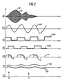
- Figure 2a shows a hint such a high-frequency structure-borne noise signal ks over time.
- the structure-borne noise signal ks is on the one hand via a diode D a low-pass filter TP1, which the envelope hk from derives the structure-borne sound signal ks (see also FIG. 2a).
- the Envelope signal hk is supplied to the microprocessor 22.
- the structure-borne noise signal is two modulators MO1 and MO2 fed. Each modulator MO1 and MO2 modulates the structure-borne sound signal ks with a carrier signal mO1 or mo2.
- the Carrier signals mo1 and mo2 are periodic signals, preferably Square wave signals with a fixed frequency f1. there is preferably the carrier signal mol over the carrier signal mo2 out of phase by 90 °.
- FIGS. 2c and 2d mo1 and mo2 The associated carrier signals are shown in FIGS. 2c and 2d mo1 and mo2 shown. Since the carrier signals with the structure-borne noise signal ks or the structure-borne noise component with the corresponding frequency F1 cannot be synchronized are two modulations, each with a phase shift Carrier signals mo1 and mo2 required.
- Figure 2e shows the modulation signals a and b at the output of the modulator MO1, which have clear levels.
- the low pass filtering the modulation signals A and B according to FIG. 2e gives the signals ATP and BTP, the temporal course of which is shown in FIG. 2f is. These signals are the microprocessor 22nd fed and squared by this and then summed.
- a final etching of the squared and then added signals ATP and BTP delivers one in the structure-borne sound signal included frequency amplitude with respect to fixed frequency F1, which in the carrier signals mol and mo2 is found.
- the switching means 21 in connection with The microprocessor 22 is therefore primarily used for the amplitude a fixed frequency in the structure-borne noise signal ks determine.
- a fixed frequency is characteristic for an impact from a certain direction.
- Such a frequency can be caused by vehicle crash tests be determined. Different vehicles with different ones Body types become different characteristics Lead frequencies.
- Figure 2f shows this proven frequency spectrum with the frequency to be verified F1 of 60 kHz, for example.
- This frequency is characteristic for a front impact and atypical, for example for a side impact, depending on the Detect this frequency F1 in the structure-borne sound signal and in particular on the amplitude of the frequency component F1 in the structure-borne noise signal a release signal Z1 to the occupant protection in the event of a front impact serving driver airbag are generated.
- the frequency amplitude is advantageously used for this purpose compared to frequency F1 with a limit value. Will the Limit exceeded by the frequency amplitude, so is the Frequency F1 significantly contained in the structure-borne noise signal ks and thus indicates a frontal impact. However, is missing a sufficiently strong frequency amplitude of the frequency F1, so the release signal Z1 is not generated and thus triggering the driver airbag 3 suppressed.
- the invention is not based on the detection of a single one fixed frequency, but also represents defining a characteristic of a direction of impact specified frequency band under protection, e.g. a frequency band from 58 to 52 kHz.
- the enable signal Z1 is only generated if at the same time as finding a minimum frequency amplitude another limit determined by the Envelope curve hk is exceeded. This further limit characterizes the severity of the impact as opposed to that Limit for the frequency amplitude, for example the delimitation a front impact from an oblique impact features.
- To generate a release signal Z1 you have to preferably an impact from the corresponding direction as well as an impact with sufficient strength from the above Evaluation of the structure-borne sound signal ks has been recognized his.
- Figure 2g also shows the exemplary frequency f0 one Envelope hk.
- Typical envelope frequencies are in the range from 0 to 500 Hz, whereas characteristic for directions of impact Frequencies range from 0 to 500 kHz.
- the invention advantageously allows detection this characteristic of impact directions and by the microprocessor 22 no longer scannable frequencies F1 by upstream circuit means 21.
- the envelope signal hk can be connected to an analog input of the microprocessor due to its low frequency and sampled by an analog-to-digital converter of the microprocessor 22 and be evaluated.
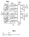
- FIG. 3 shows an expansion according to the invention compared to FIG Contraption.
- the microprocessor 22 controls one Airbag 31 for front impact protection and an airbag 32 for Side impact protection. Furthermore, an acceleration sensor 4 for accelerations parallel to the vehicle's longitudinal axis and an acceleration sensor 5 for recording accelerations connected transversely to the vehicle's longitudinal axis. Also included the circuitry upstream of the microprocessor 22 not just first circuit means 211 for supplying signals ATP and BTP in the manner explained with reference to FIG. 1 as well as further circuit means 212 for determining the envelope hk. In addition, third circuit means 213 are provided, that are identical to the first circuit means 212 are trained. Thus the third circuit means contain 213 modulators MO3 and MO4 as well as low pass filters TP4 and TP5.
- the mode of operation of the third circuit means 213 differs only in the supplied carrier frequencies mo3 and mo4 on the functioning of the first circuit means 212.
- the carrier signals mo3 and mo4 have one of the Frequency of the carrier signals mol and mo2 different frequency f2 on.
- the third circuit arrangement 213, also the structure-borne noise signal ks is thus used to prepare the determination of the frequency amplitude of the Frequency f2.
- the microprocessor 22 carries out the function shown in FIG known way by squaring the signal CTP and DTP and a subsequent addition and root formation a comparison with a limit that is used to determine the Presence of a signal component with the frequency f2 im Spectrum of the structure-borne sound signal ks is used.
- the frequency f2 be characteristic of a side impact.
- FIG. 4 shows such exemplary frequencies f1 and f2 in the frequency band, where the frequency f0 in turn the fundamental oscillation of the envelope curve hk is to be assigned.
- the control of the occupant protection means 31 and 32 takes place as follows: by evaluating the longitudinal acceleration signal of the acceleration sensor 4 is sufficient strong front impact detected. Thereupon the trigger signal A1 is output to an AND gate 311. Triggering the Front airbags 31, however, only take place regularly if the Microprocessor also the enable signal Z1 to the AND gate 311 supplies. The release signal Z1 is only then regular generated when the envelope curve hk exceeds a limit value and at the same time the frequency f1 by means of the first Circuit means 211 is recognized in the structure-borne sound signal ks.
- the microprocessor 22 evaluates the lateral acceleration signal in the same way of the acceleration sensor 5 and generated a trigger signal A2 if a sufficiently strong impact is recognized.
- the side airbag 32 becomes regular only triggered if an enable signal is given at the same time Z2 is present.
- This release signal Z2 becomes regular generated when the envelope exceeds the limit and at the same time the frequency F2 by the third circuit means 213 in the frequency spectrum of the structure-borne sound signal ks is recognized.
- the device of Figure 3 has the advantage that an impact detected by at least two sensor means 1, 4 or 1, 5 must be, with the sensor means 1 and 4 and 5 respectively different physical principles.
- the security for false tripping can be further increased by only the Acceleration signals are processed in the microprocessor, however, an evaluation of the signals ATP, BTP, CTP, DTP and hk is released from the microprocessor 22 and in one Hardware circuitry is performed.
Landscapes
- Engineering & Computer Science (AREA)
- Mechanical Engineering (AREA)
- Air Bags (AREA)
Description
- Figur 1
- ein erstes Blockschaltbild einer erfindungsgemäßen Vorrichtung,
- Figur 2
- Signalverläufe über der Zeit in Zusammenhang mit der Auswertung des Körperschallsignals,
- Figur 3
- ein Blockschaltbild einer weiteren erfindungsgemäßen Vorrichtung und
- Figur 4
- ein Frequenzspektrum.
Claims (15)
- Vorrichtung zum Steuern eines Insassenschutzmittels eines Fahrzeugs,wobeimit einem Körperschallsensor (1) zum Aufnehmen von Karosserieschwingungen, undmit einem Auswerter (2) zum Steuern des Insassenschutzmittels (3) abhängig von einem vom Körperschallsensor (1) abgegebenen Körperschallsignal (ks),
der Auswerter (2) elektrische Schaltungsmittel (211) zum Feststellen einer festgelegten Frequenz (f1) im Körperschallsignal (ks) enthält, und dadurch gekennzeichnet, daß der Auswerter (2) weitere elektrische Schaltungsmittel (212) zum Ableiten einer Hüllkurve (hk) aus dem Körperschallsignal (ks) enthält, und daß der Auswerter (2) zum Erzeugen eines Freigabesignals (z1) für das Insassenschutzmittel (3) in Abhängigkeit von der Hüllkurve (hk) und von der festgestellten Frequenz (f1) ausgebildet ist. - Vorrichtung nach Anspruch 1, dadurch gekennzeichnet, daß der Auswerter (2) zum Erzeugen eines Freigabesignals (z1) für das Insassenschutzmittel (3) in Abhängigkeit von der festgestellten Frequenz (f1) ausgebildet ist.
- Vorrichtung nach einem der vorhergehenden Ansprüche, dadurch gekennzeichnet, daß der Auswerter (2) dritte elektrische Schaltungsmittel (213) zum Feststellen zumindest einer weiteren festgelegten Frequenz (f2) im Körperschallsignal (ks) enthält.
- Vorrichtung nach Anspruch 3, dadurch gekennzeichnet, daß sie zum Steuern mehrerer Insassenschutzmittel (31,32) ausgebildet ist, und daß der Auswerter (2) zum Auswählen eines Insassenschutzmittels (31,32) in Abhängigkeit der festgestellten Frequenzen (f1,f2) ausgebildet ist.
- Vorrichtung nach einem der vorhergehenden Ansprüche, dadurch gekennzeichnet, daß die weiteren Schaltungsmittel (212) zum Erzeugen der Hüllkurve (hk) ein Tiefpaßfilter (TP1) enthalten.
- Vorrichtung nach einem der vorhergehenden Ansprüche, dadurch gekennzeichnte, daß die Schaltungsmittel (211) einen Modulator (MO1) zum Multiplizieren des Körperschallsignals (ks) mit einem periodischen Signal (mo1), das die festgelegte Frequenz (f1) aufweist, enthalten,sowie einen weiteren Modulator (MO2) zum Multiplizieren des Körperschallsignals (ks) mit einem weiteren periodischen Signal (mo2), das die festgelegte Frequenz (f1) aufweist und eine zum ersten periodischen Signal (mol) verschobene Phase.
- Vorrichtung nach Anspruch 6, dadurch gekennzeichnet, daß die Ausgänge des ersten und des weiteren Modulators (MO1,MO2) mit jeweils einem Tiefpaßfilter (TP2,TP3) verbunden sind.
- Vorrichtung nach Anspruch 7, dadurch gekennzeichnet, daß der Auswerter (2) einen Mikroprozessor (22) enthält, der mit den Tiefpaßfiltern (TP1,TP2,TP3) verbunden ist.
- Vorrichtung nach Anspruch 7 oder Anspruch 8, dadurch gekennzeichnet, daß der Auswerter (2) zum Quadrieren der Signale an den Ausgängen der Tiefpaßfilter (TP2,TP3) zum Addieren der quadrierten Signale und zum anschließenden Radizieren zu einer Frequenzamplitude ausgebildet ist.
- Vorrichtung nach Anspruch 5 und Anspruch 9, dadurch gekennzeichnet, daß der Auswerter (2) zum Erzeugen des Freigabesignals (z1) für das Insassenschutzmittel (3) ausgebildet ist, wenn die Frequenzamplitude einen ersten Grenzwert überschreitet, und wenn die Hüllkurve (hk) einen weiteren Grenzwert überschreitet.
- Vorrichtung nach Anspruch 3, dadurch gekennzeichnet, daß die dritten Schaltungsmittel (213) einen Modulator (MO3) zum Multiplizieren des Körperschallsignals (ks) mit einem periodischen Signal (mo3), das die weitere festgelegte Frequenz (f2) aufweist, enthalten sowie einen weiteren Modulator (MO4) zum Multiplizieren des Körperschallsignals (ks) mit einem weiteren periodischen Signal (mo4), das die weitere festgelegte Frequenz (f2) aufweist und eine zum ersten periodischen Signal verschobene Phase.
- Vorrichtung nach Anspruch 11, dadurch gekennzeichnet, daß die Ausgänge des ersten und des weiteren Modulators (MO3,MO4) der dritte Schaltungsmittel (213) mit jeweils einem Tiefpaßfilter (TP4,TP5) verbunden ist.
- Vorrichtung nach Anspruch 12, dadurch gekennzeichnet, daß der Auswerter (2) zum Quadrieren der Signale an den Ausgängen der Tiefpaßfilter (TP4,TP5) der dritten Schaltungsmittel (213), zum Addieren der quadrierten Signale und zum anschließenden Radizieren zu einer weiteren Frequenzamplitude ausgebildet ist.
- Vorrichtung nach Anspruch 13, dadurch gekennzeichnet, daß der Auswerter (2) zum Erzeugen eines weiteren Freigabesignals (z2) für ein weiteres Insassenschutzmittel ausgebildet ist, wenn die weitere Frequenzamplitude einen dritten Grenzwert überschreitet und wenn die Hüllkurve den weiteren Grenzwert überschreitet.
- Vorrichtung nach einem der vorhergehenden Ansprüche, dadurch gekennzeichnet, daß der Auswerter (2) zum Erzeugen des Freigabesignals (z1) für das Insassenschutzmittel (3) ausgebildet ist, wenn die festgelegte Frequenz festgestellt wird und wenn die Hüllkurve (hk) einen weiteren Grenzwert überschreitet.
Applications Claiming Priority (3)
| Application Number | Priority Date | Filing Date | Title |
|---|---|---|---|
| DE19855452A DE19855452A1 (de) | 1998-12-01 | 1998-12-01 | Vorrichtung zum Steuern eines Insassenschutzmittels eines Fahrzeugs |
| DE19855452 | 1998-12-01 | ||
| PCT/DE1999/003811 WO2000032450A1 (de) | 1998-12-01 | 1999-12-01 | Vorrichtung zum steuern eines insassenschutzmittels eines fahrzeugs |
Publications (2)
| Publication Number | Publication Date |
|---|---|
| EP1135283A1 EP1135283A1 (de) | 2001-09-26 |
| EP1135283B1 true EP1135283B1 (de) | 2002-11-13 |
Family
ID=7889659
Family Applications (1)
| Application Number | Title | Priority Date | Filing Date |
|---|---|---|---|
| EP99965384A Expired - Lifetime EP1135283B1 (de) | 1998-12-01 | 1999-12-01 | Vorrichtung zum steuern eines insassenschutzmittels eines fahrzeugs |
Country Status (3)
| Country | Link |
|---|---|
| EP (1) | EP1135283B1 (de) |
| DE (2) | DE19855452A1 (de) |
| WO (1) | WO2000032450A1 (de) |
Families Citing this family (25)
| Publication number | Priority date | Publication date | Assignee | Title |
|---|---|---|---|---|
| DE10245780B4 (de) * | 2002-10-01 | 2010-10-14 | Robert Bosch Gmbh | Vorrichtung zur Aufprallerkennung mittels Körperschall in einem Fahrzeug |
| US8401739B2 (en) * | 2003-10-09 | 2013-03-19 | Conti Temic Microelectronic, Gmbh | Device for activating a security system in a vehicle |
| US7856880B2 (en) | 2004-03-26 | 2010-12-28 | Conti Temic Microelectronics Gmbh | Vehicle sensor for detecting impact sound |
| DE102004022822A1 (de) * | 2004-05-08 | 2005-12-01 | Conti Temic Microelectronic Gmbh | Aufnehmersystem/Auslösesensor, geeignet für Diagnose-/Sicherheitsvorrichtung, insbesondere für Unfallschutzeinrichtungen in einem Fahrzeug |
| DE102004022830A1 (de) * | 2004-05-08 | 2005-12-01 | Conti Temic Microelectronic Gmbh | Aufnehmersystem/Auslösesensor, geeignet für Diagnose-/Sicherheitsvorrichtung, insbesondere für Unfallschutzeinrichtungen in einem Fahrzeug |
| DE102004022808A1 (de) * | 2004-05-08 | 2005-12-01 | Conti Temic Microelectronic Gmbh | Aufnehmersystem/Auslösesensor, geeignet für Diagnose-/Sicherheitsvorrichtung, insbesondere für Unfallschutzeinrichtungen in einem Fahrzeug |
| DE102004022831A1 (de) * | 2004-05-08 | 2005-12-01 | Conti Temic Microelectronic Gmbh | Aufnehmersystem/Auslösesensor, geeignet für Diagnose-/Sicherheitsvorrichtung, insbesondere für Unfallschutzeinrichtungen in einem Fahrzeug |
| DE102004031557B4 (de) | 2004-06-29 | 2016-12-22 | Conti Temic Microelectronic Gmbh | Verfahren und Crash-Sensor für eine Vorrichtung zur insassengefährdungsrelevanten Aktivierung von Insassen-Schutzeinrichtungen in einem Kraftfahrzeug bei Crashfällen |
| DE102004049380B4 (de) * | 2004-10-09 | 2017-02-02 | Conti Temic Microelectronic Gmbh | Fahrzeugsensor |
| EP1827913B1 (de) * | 2004-12-22 | 2008-04-16 | Bayerische Motoren Werke Aktiengesellschaft | Verfahren zum ansteuern eines sicherheitssystems in einem fahrzeug |
| US7158017B2 (en) | 2004-12-22 | 2007-01-02 | Bayerische Motoren Werke Aktiengesellschaft | Method for controlling a safety system in a vehicle |
| DE102005014013A1 (de) * | 2005-03-26 | 2006-09-28 | Conti Temic Microelectronic Gmbh | Fahrzeugsensor |
| DE102005024319B3 (de) * | 2005-05-27 | 2006-12-14 | Siemens Ag | Vorrichtung und Verfahren zum Steuern eines Personenschutzsystems eines Fahrzeugs |
| DE102005034589A1 (de) * | 2005-07-25 | 2007-02-01 | Conti Temic Microelectronic Gmbh | Anordnung und Verfahren zur richtungssensitiven Erfassung mechanischer Schwingungen |
| DE102005042512B4 (de) * | 2005-09-07 | 2007-06-14 | Siemens Ag | Verfahren zum Aktivieren einer Fußgängerschutzvorrichtung eines Kraftfahrzeugs |
| DE102006008638B4 (de) * | 2006-02-24 | 2015-06-11 | Robert Bosch Gmbh | Verfahren und Vorrichtung zur Unfallklassifizierung für ein Fahrzeug |
| DE102006026057A1 (de) * | 2006-06-03 | 2007-12-06 | Wilhelm Karmann Gmbh | Verfahren und Vorrichtung zum Betrieb eines Cabrioletverdecks |
| DE102006038844B4 (de) | 2006-08-18 | 2018-03-22 | Robert Bosch Gmbh | Vorrichtung und Verfahren zur Ansteuerung von Personenschutzmittel |
| DE102007002996B4 (de) * | 2007-01-20 | 2016-12-01 | Conti Temic Microelectronic Gmbh | Verfahren zum Steuern eines Personenschutzsystems eines Fahrzeugs sowie entsprechende Steuereinheit |
| DE102007008379B4 (de) * | 2007-02-21 | 2015-01-15 | Robert Bosch Gmbh | Steuergerät und Verfahren zur Ansteuerung von Personenschutzmitteln |
| DE102007027492A1 (de) * | 2007-06-14 | 2008-12-18 | Robert Bosch Gmbh | Verfahren und Steuergerät zur Ansteuerung von Personenschutzmitteln für ein Fahrzeug |
| DE102007046982B3 (de) * | 2007-10-01 | 2009-03-05 | Fendt, Günter | Einrichtung zur Erfassung einer Unfallsituation und Verfahren zum Erkennen einer Unfallsituation und/oder zum Steuern eines Personschutzsystems |
| DE102007048883A1 (de) * | 2007-10-11 | 2009-04-16 | Robert Bosch Gmbh | Verfahren und Steuergerät zur Aufprallerkennung für ein Fahrzeug |
| DE102009038430A1 (de) * | 2009-05-06 | 2010-11-11 | Continental Automotive Gmbh | Verfahren zur Aufprallerkennung bei Kraftfahrzeugen mit mindestens einer Körperschallerzeugungseinrichtung |
| DE102011006984A1 (de) * | 2011-04-07 | 2012-10-11 | Robert Bosch Gmbh | Verfahren und Vorrichtung zur Auswertung von Körperschall bei einer Kollision eines Fahrzeugs |
Family Cites Families (3)
| Publication number | Priority date | Publication date | Assignee | Title |
|---|---|---|---|---|
| DE3729019A1 (de) * | 1987-08-31 | 1989-03-16 | Messerschmitt Boelkow Blohm | Einrichtung zur ausloesung einer sicherheitsvorrichtung |
| US5185701A (en) * | 1989-11-03 | 1993-02-09 | Trw Vehicle Safety Systems Inc. | Method for determining frequency components in a vehicle crash |
| DE9215382U1 (de) * | 1992-11-11 | 1994-03-17 | Siemens AG, 80333 München | In einem Fahrzeug angebrachter Schalldetektor |
-
1998
- 1998-12-01 DE DE19855452A patent/DE19855452A1/de not_active Withdrawn
-
1999
- 1999-12-01 DE DE59903431T patent/DE59903431D1/de not_active Expired - Lifetime
- 1999-12-01 WO PCT/DE1999/003811 patent/WO2000032450A1/de not_active Ceased
- 1999-12-01 EP EP99965384A patent/EP1135283B1/de not_active Expired - Lifetime
Also Published As
| Publication number | Publication date |
|---|---|
| EP1135283A1 (de) | 2001-09-26 |
| DE59903431D1 (de) | 2002-12-19 |
| WO2000032450A1 (de) | 2000-06-08 |
| DE19855452A1 (de) | 2000-06-15 |
Similar Documents
| Publication | Publication Date | Title |
|---|---|---|
| EP1135283B1 (de) | Vorrichtung zum steuern eines insassenschutzmittels eines fahrzeugs | |
| DE19848997B4 (de) | Fahrzeuginsassenschutzsystem | |
| EP1019271B1 (de) | Vorrichtung für den insassenschutz in einem kraftfahrzeug | |
| DE19645952C2 (de) | Steueranordnung für ein Rückhaltemittel in einem Kraftfahrzeug | |
| DE4116336C1 (en) | Passive safety device release assembly for motor vehicle occupant - has acceleration pick=ups with sensitivity axes directed to detect angle of frontal impact and supplying evaluating circuit | |
| DE19611973B4 (de) | Verfahren und Vorrichtung zum Erfassen eines auf ein Fahrzeug einwirkenden Stoßes | |
| EP0810129B1 (de) | Auslöseverfahren für passive Sicherheitseinrichtungen in Fahrzeugen | |
| EP2315686B1 (de) | Verfahren zur ermittlung eines unfallschwerekriteriums mittels eines beschleunigungssignals und eines körperschallsignals | |
| EP0807558B1 (de) | Auslöseverfahren für passive Sicherheitseinrichtungen in Fahrzeugen | |
| EP0830271B1 (de) | Steueranordnung zur auslösung eines rückhaltemittels in einem fahrzeug bei einem seitenaufprall | |
| DE3816587A1 (de) | Einrichtung zur ausloesung einer passiven sicherheitseinrichtung | |
| DE102008040590A1 (de) | Verfahren und Steuergerät zur Ansteuerung von Personenschutzmitteln für ein Fahrzeug | |
| DE19537546B4 (de) | Aufprallerkennungsvorrichtung, insbesondere für ein Sicherheitssystem für Fahrzeuge zur Personenbeförderung | |
| DE4208714A1 (de) | Verfahren zur detektierung eines fahrzeugzusammenstosses | |
| DE19623520A1 (de) | Auslösevorrichtung für eine Sicherheitsvorrichtung | |
| DE19806836C1 (de) | Vorrichtung zum Steuern eines Insassenschutzmittels eines Kraftfahrzeugs, insbesondere zum Seitenaufprallschutz | |
| EP0904989A2 (de) | Verfahren und Einrichtung zur Aktivierung von Insassenschutzsystemen in Kraftfahrzeugen | |
| DE19854529B4 (de) | Auslösesteuerungsverfahren und -system für ein Insassenschutzsystem | |
| EP2240346B1 (de) | Verfahren und steuergerät zur ansteuerung von personenschutzmitteln für ein fahrzeug | |
| EP1423301A1 (de) | Verfahren zur bestimmung einer auslösezeit für rückhaltemittel in einem fahrzeug | |
| WO2007036565A1 (de) | Vorrichtung und verfahren zur lokalisierung einer kollision eines objektes an einem kraftfahrzeug | |
| DE102007047404A1 (de) | Verfahren zum Auslösen von einem Rückhaltemittel bei einem Fahrzeugcrash | |
| DE102007046982B3 (de) | Einrichtung zur Erfassung einer Unfallsituation und Verfahren zum Erkennen einer Unfallsituation und/oder zum Steuern eines Personschutzsystems | |
| DE102005002779B4 (de) | Passives Sicherheitssystem und Bestimmungsvorrichtung | |
| EP1409298B2 (de) | Einrichtung und verfahren zur auslösung eines insassenschutzmittels in einem kraftfahrzeug |
Legal Events
| Date | Code | Title | Description |
|---|---|---|---|
| PUAI | Public reference made under article 153(3) epc to a published international application that has entered the european phase |
Free format text: ORIGINAL CODE: 0009012 |
|
| 17P | Request for examination filed |
Effective date: 20010307 |
|
| AK | Designated contracting states |
Kind code of ref document: A1 Designated state(s): AT BE CH CY DE DK ES FI FR GB GR IE IT LI LU MC NL PT SE |
|
| GRAG | Despatch of communication of intention to grant |
Free format text: ORIGINAL CODE: EPIDOS AGRA |
|
| 17Q | First examination report despatched |
Effective date: 20020208 |
|
| GRAG | Despatch of communication of intention to grant |
Free format text: ORIGINAL CODE: EPIDOS AGRA |
|
| GRAH | Despatch of communication of intention to grant a patent |
Free format text: ORIGINAL CODE: EPIDOS IGRA |
|
| GRAH | Despatch of communication of intention to grant a patent |
Free format text: ORIGINAL CODE: EPIDOS IGRA |
|
| GRAA | (expected) grant |
Free format text: ORIGINAL CODE: 0009210 |
|
| AK | Designated contracting states |
Kind code of ref document: B1 Designated state(s): DE FR GB IT |
|
| REG | Reference to a national code |
Ref country code: GB Ref legal event code: FG4D Free format text: NOT ENGLISH |
|
| GBT | Gb: translation of ep patent filed (gb section 77(6)(a)/1977) |
Effective date: 20021113 |
|
| REG | Reference to a national code |
Ref country code: IE Ref legal event code: FG4D Free format text: GERMAN |
|
| REF | Corresponds to: |
Ref document number: 59903431 Country of ref document: DE Date of ref document: 20021219 |
|
| ET | Fr: translation filed | ||
| REG | Reference to a national code |
Ref country code: IE Ref legal event code: FD4D Ref document number: 1135283E Country of ref document: IE |
|
| PLBE | No opposition filed within time limit |
Free format text: ORIGINAL CODE: 0009261 |
|
| STAA | Information on the status of an ep patent application or granted ep patent |
Free format text: STATUS: NO OPPOSITION FILED WITHIN TIME LIMIT |
|
| 26N | No opposition filed |
Effective date: 20030814 |
|
| REG | Reference to a national code |
Ref country code: FR Ref legal event code: TP |
|
| REG | Reference to a national code |
Ref country code: GB Ref legal event code: 732E Free format text: REGISTERED BETWEEN 20110825 AND 20110831 |
|
| PGFP | Annual fee paid to national office [announced via postgrant information from national office to epo] |
Ref country code: GB Payment date: 20141219 Year of fee payment: 16 Ref country code: DE Payment date: 20141231 Year of fee payment: 16 |
|
| PGFP | Annual fee paid to national office [announced via postgrant information from national office to epo] |
Ref country code: FR Payment date: 20141219 Year of fee payment: 16 |
|
| PGFP | Annual fee paid to national office [announced via postgrant information from national office to epo] |
Ref country code: IT Payment date: 20141223 Year of fee payment: 16 |
|
| REG | Reference to a national code |
Ref country code: DE Ref legal event code: R119 Ref document number: 59903431 Country of ref document: DE |
|
| GBPC | Gb: european patent ceased through non-payment of renewal fee |
Effective date: 20151201 |
|
| REG | Reference to a national code |
Ref country code: FR Ref legal event code: ST Effective date: 20160831 |
|
| PG25 | Lapsed in a contracting state [announced via postgrant information from national office to epo] |
Ref country code: DE Free format text: LAPSE BECAUSE OF NON-PAYMENT OF DUE FEES Effective date: 20160701 Ref country code: GB Free format text: LAPSE BECAUSE OF NON-PAYMENT OF DUE FEES Effective date: 20151201 |
|
| PG25 | Lapsed in a contracting state [announced via postgrant information from national office to epo] |
Ref country code: FR Free format text: LAPSE BECAUSE OF NON-PAYMENT OF DUE FEES Effective date: 20151231 |
|
| PG25 | Lapsed in a contracting state [announced via postgrant information from national office to epo] |
Ref country code: IT Free format text: LAPSE BECAUSE OF NON-PAYMENT OF DUE FEES Effective date: 20151201 |