EP1135234B1 - Inducing physical changes in metal objects - Google Patents
Inducing physical changes in metal objects Download PDFInfo
- Publication number
- EP1135234B1 EP1135234B1 EP99957031A EP99957031A EP1135234B1 EP 1135234 B1 EP1135234 B1 EP 1135234B1 EP 99957031 A EP99957031 A EP 99957031A EP 99957031 A EP99957031 A EP 99957031A EP 1135234 B1 EP1135234 B1 EP 1135234B1
- Authority
- EP
- European Patent Office
- Prior art keywords
- energy
- pmf
- discharge
- workpiece
- mechanical energy
- Prior art date
- Legal status (The legal status is an assumption and is not a legal conclusion. Google has not performed a legal analysis and makes no representation as to the accuracy of the status listed.)
- Expired - Lifetime
Links
- 239000002184 metal Substances 0.000 title claims abstract description 54
- 230000001939 inductive effect Effects 0.000 title claims abstract description 24
- 230000008859 change Effects 0.000 claims abstract description 25
- 238000000034 method Methods 0.000 claims abstract description 24
- 238000003466 welding Methods 0.000 claims description 38
- 239000012530 fluid Substances 0.000 claims description 18
- 230000035939 shock Effects 0.000 claims description 12
- 238000007599 discharging Methods 0.000 claims description 8
- 239000007788 liquid Substances 0.000 claims description 2
- 238000002604 ultrasonography Methods 0.000 claims description 2
- 239000007787 solid Substances 0.000 claims 2
- 208000028659 discharge Diseases 0.000 description 33
- 239000003990 capacitor Substances 0.000 description 10
- 230000008569 process Effects 0.000 description 4
- 239000007864 aqueous solution Substances 0.000 description 2
- 230000000694 effects Effects 0.000 description 2
- 230000002093 peripheral effect Effects 0.000 description 2
- 230000004913 activation Effects 0.000 description 1
- 230000015572 biosynthetic process Effects 0.000 description 1
- 230000002301 combined effect Effects 0.000 description 1
- 238000010438 heat treatment Methods 0.000 description 1
- 230000003993 interaction Effects 0.000 description 1
- 238000004021 metal welding Methods 0.000 description 1
- 230000004048 modification Effects 0.000 description 1
- 238000012986 modification Methods 0.000 description 1
- 230000010355 oscillation Effects 0.000 description 1
- XLYOFNOQVPJJNP-UHFFFAOYSA-N water Substances O XLYOFNOQVPJJNP-UHFFFAOYSA-N 0.000 description 1
Images


Classifications
-
- B—PERFORMING OPERATIONS; TRANSPORTING
- B23—MACHINE TOOLS; METAL-WORKING NOT OTHERWISE PROVIDED FOR
- B23K—SOLDERING OR UNSOLDERING; WELDING; CLADDING OR PLATING BY SOLDERING OR WELDING; CUTTING BY APPLYING HEAT LOCALLY, e.g. FLAME CUTTING; WORKING BY LASER BEAM
- B23K20/00—Non-electric welding by applying impact or other pressure, with or without the application of heat, e.g. cladding or plating
- B23K20/06—Non-electric welding by applying impact or other pressure, with or without the application of heat, e.g. cladding or plating by means of high energy impulses, e.g. magnetic energy
-
- B—PERFORMING OPERATIONS; TRANSPORTING
- B21—MECHANICAL METAL-WORKING WITHOUT ESSENTIALLY REMOVING MATERIAL; PUNCHING METAL
- B21D—WORKING OR PROCESSING OF SHEET METAL OR METAL TUBES, RODS OR PROFILES WITHOUT ESSENTIALLY REMOVING MATERIAL; PUNCHING METAL
- B21D26/00—Shaping without cutting otherwise than using rigid devices or tools or yieldable or resilient pads, i.e. applying fluid pressure or magnetic forces
- B21D26/02—Shaping without cutting otherwise than using rigid devices or tools or yieldable or resilient pads, i.e. applying fluid pressure or magnetic forces by applying fluid pressure
- B21D26/06—Shaping without cutting otherwise than using rigid devices or tools or yieldable or resilient pads, i.e. applying fluid pressure or magnetic forces by applying fluid pressure by shock waves
- B21D26/12—Shaping without cutting otherwise than using rigid devices or tools or yieldable or resilient pads, i.e. applying fluid pressure or magnetic forces by applying fluid pressure by shock waves initiated by spark discharge
-
- B—PERFORMING OPERATIONS; TRANSPORTING
- B21—MECHANICAL METAL-WORKING WITHOUT ESSENTIALLY REMOVING MATERIAL; PUNCHING METAL
- B21D—WORKING OR PROCESSING OF SHEET METAL OR METAL TUBES, RODS OR PROFILES WITHOUT ESSENTIALLY REMOVING MATERIAL; PUNCHING METAL
- B21D26/00—Shaping without cutting otherwise than using rigid devices or tools or yieldable or resilient pads, i.e. applying fluid pressure or magnetic forces
- B21D26/14—Shaping without cutting otherwise than using rigid devices or tools or yieldable or resilient pads, i.e. applying fluid pressure or magnetic forces applying magnetic forces
-
- B—PERFORMING OPERATIONS; TRANSPORTING
- B23—MACHINE TOOLS; METAL-WORKING NOT OTHERWISE PROVIDED FOR
- B23K—SOLDERING OR UNSOLDERING; WELDING; CLADDING OR PLATING BY SOLDERING OR WELDING; CUTTING BY APPLYING HEAT LOCALLY, e.g. FLAME CUTTING; WORKING BY LASER BEAM
- B23K11/00—Resistance welding; Severing by resistance heating
- B23K11/10—Spot welding; Stitch welding
- B23K11/11—Spot welding
- B23K11/115—Spot welding by means of two electrodes placed opposite one another on both sides of the welded parts
-
- B—PERFORMING OPERATIONS; TRANSPORTING
- B23—MACHINE TOOLS; METAL-WORKING NOT OTHERWISE PROVIDED FOR
- B23K—SOLDERING OR UNSOLDERING; WELDING; CLADDING OR PLATING BY SOLDERING OR WELDING; CUTTING BY APPLYING HEAT LOCALLY, e.g. FLAME CUTTING; WORKING BY LASER BEAM
- B23K20/00—Non-electric welding by applying impact or other pressure, with or without the application of heat, e.g. cladding or plating
- B23K20/10—Non-electric welding by applying impact or other pressure, with or without the application of heat, e.g. cladding or plating making use of vibrations, e.g. ultrasonic welding
-
- C—CHEMISTRY; METALLURGY
- C21—METALLURGY OF IRON
- C21D—MODIFYING THE PHYSICAL STRUCTURE OF FERROUS METALS; GENERAL DEVICES FOR HEAT TREATMENT OF FERROUS OR NON-FERROUS METALS OR ALLOYS; MAKING METAL MALLEABLE, e.g. BY DECARBURISATION OR TEMPERING
- C21D10/00—Modifying the physical properties by methods other than heat treatment or deformation
Definitions
- the invention relates to methods and apparatus for inducing physical changes in metal objects in general and making use of pulsed magnetic force (PMF) energy therefor, in particular.
- PMF pulsed magnetic force
- the present invention is directed to a method and apparatus for working, i.e. inducing physical change in at least one metal workpiece.
- physical change denotes structural change in form or shape, cutting off of a portion of a workpiece, perforation of a workpiece, joining of two or more workpieces to one another or welding two workpieces or portions thereof to one another.
- joining used before and further below means to denote a tight engagement of two workpieces to one another, for example, tight fitting of a generally cylindrical object over a tubular object fitted within it; and the term “ welding ", in distinction from joining, means to denote a very tight interaction of the surfaces of two objects, e.g. metalurgical bonding of at least a portion of the two workpieces.
- the method and apparatus of the invention make use of pulsed magnetic force (PMF) energy.
- PMF energy is combined with another energy from a separate energy source which acts synergistically with the PMF energy to impart a physical change.
- the other energy source (to be referred to herein at times as the "auxiliary energy source ”) may be another PMF energy, may be a mechanical energy source, and many others.
- a method for inducing a physical change in at least one metal workpiece comprising:
- an apparatus for inducing a physical change in at least one metal workpiece comprising:
- transferring energy or any similar term which may be used herein, means to denote the transfer of energy to a workpiece in a form which at least partially acts to yield said physical change.
- metal workpiece refers to any metal object which is to be worked by the method or apparatus of the invention, which may be a cylindrical object which is to be joined or welded to a tubular or another cylindrical objection; a metal plate which is to be formed, cut or perforated; etc.
- the invention is not limited to a workpiece of any specific kind but rather can be applied for a myriad of different workpieces and for inducing a wide variety of different physical changes.
- combination of energies means to denote the timed activation of the at least two energy sources to transfer their respective energies to the at least one workpiece such that the periods of their transfer at least partially overlap, whereby the combined effect of the two energies, as far as inducing the physical change, is substantially larger than the physical change which may be imparted by only one of the energy sources.
- the combination of energies in accordance with the invention gives rise to a variety of improvements over the use of PMF alone. For example, in the case of welding or joining of two metal workpieces to one another, the same result may be achieved with a lower PMF energy as compared to PMF alone. This may have design consequences as the generation of a large PMF necessitates large capacitor banks and thus an apparatus in accordance with the invention may have an overall smaller size.
- the present invention allows the achievements of results, which may be difficult to achieve in accordance with the prior art.
- the strong impact of the external one onto the internal one may give rise to squeezing or crushing of the internal tubular workpiece.
- the combination of energies in accordance with the invention may give rise to an increase of the area of the weld.
- the time period overlap be substantial, meaning that at least one of the energies is applied such that throughout most of its period of application, it overlaps the other applied energy This may mean, for example, that both may begin and end simultaneously, both may begin simultaneously and end in succession, both may begin in succession but end simultaneously, one beginning and ending during the period the other energy is applied, and various combinations of these scenarios.
- the other energy source may be selected from a wide variety of different sources.
- the other energy source is a device for generating a mechanical shock wave or mechanical vibrations in the workpiece; a device which can generate ultrasonic vibrations within the object, e.g. a device as customary used in ultrasonic welding.
- the primary and the auxiliary energies which are used in combination in accordance with the invention, are superimposed, namely they are generated such that there are applied for periods of time overlapping one another over substantial portions thereof.
- the primary PMF energy is generated simultaneously with the auxiliary energy.
- the auxiliary energy is initiated prior or after the primary PMF energy
- the total amount of the transferred primary energy may be larger than the total amount of the transferred auxiliary energy, at times they may be about the same or at time the total of the auxiliary energy may exceed the total of the primary energy.
- said auxiliary energy is a mechanical energy imparted by inducing rapid movement in at least one of the two metal objects.
- Such movement may be a mechanical shock or vibrations.
- the mechanical energy is imparted onto the at least one metal object by means of a mechanical waveguide.
- the waveguide may be associated with an auxiliary working coil connected to a current discharge circuitry which, by means of a PMF, generates mechanical vibration waves in said waveguide which are then transmitted to the metal object.
- the waveguide may be associated with a discharge-in-fluid (DIF) device, which generates a shock wave, which is then transmitted by the waveguide to at least one of the objects.
- DIF discharge-in-fluid
- the DIF device comprises a fluid chamber with discharge electrodes provided within the chamber for discharging an electric current between them and through the fluid.
- a plasma forms within the fluid which generates a shock wave within the fluid which is then transmitted to the waveguide.
- the fluid is typically an aqueous solution.
- the mechanical energy is an ultrasonic energy.
- the welding embodiment is a preferred embodiment of the present invention.
- a method according to Claim 1 for welding two metal objects to one another, comprising:
- an apparatus according to Claim 12 for welding of two metal objects to one another comprising:
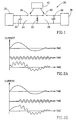
- Discharge circuitry 24 consists of a power supply 30, a capacitor battery 32, which may consist of a single or a plurality of capacitors and a high current switch 34.
- discharge circuitry 26 consists of a power supply 36, capacitor battery 38 and a switch 40.
- Switches 34 and 40 are controlled by means of an ignition circuitry 42 which provides a trigger to these switches.
- Switches 34 and 40 may be any one of a variety of high current switches known per se , such as a controlled vacuum discharger of the kind disclosed in PCT Application No. PCT/IL 97/00383.
- Circuitry 24 is designated here as the primary circuitry and circuitry 26 as the auxiliary circuitry.
- both the primary discharge current of circuitry 34 and the auxiliary discharge current of circuitry 26 are discharged through the single working coil 22.
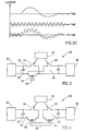
- Figs. 2A-2C show several different combinations of a primary and auxiliary discharge currents to yield a combined, superimposed PMF-generating current.
- the primary discharged current which is represented by the upper curve of Figs. 2A-2C, has typically an amplitude of about 10-200 kA, typically 100 kA and an initial oscillation frequency of about 10-100 KHz.
- the auxiliary discharged current illustrated as the middle curve in each of Figs. 2A-2C has typically a frequency of about 50-1000 KHz and an amplitude of about 1-10 kA.
- the two different current may be discharged simultaneously (Fig. 2A); or the auxiliary current may be discharged after (Fig. 2B) or prior (Fig. 2C) the primary current.
- the superimposed current is illustrated as the lower curve in each of Figs. 2A-2C. It has been realized that such a superimposed PMF current gives rise to efficient welding, without the need to substantially increase the current intensity and fine tune the current discharge parameters, as was needed in the prior art PMF processes.
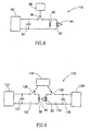
- Figs. 3 and 4 show a scheme of apparatuses 50 and 60 respectively, in accordance with two other examples which are useful for understanding the invention.
- the apparatus 50 of Fig. 3 differs from that of Fig. 1, in that coil 52 which is connected to both circuitries, is in inductive relationship with forming coil 54, in this specific example a single wind coil.
- the primary discharge circuitry 24 and the auxiliary discharge circuitry 26 are independent and are provided with coil 62 and 64 respectively, which are in inductive association with forming coil 66.
- FIG. 5 An apparatus 70 in accordance with another example which is useful for understanding the invention is shown in Fig. 5.
- discharge circuitry 26 is provided with a high frequency generator 72, typically capable of generating current at a frequency of about 100-1000 KHz, which is connected to coil 22 through high voltage breaker 74, e.g. a Fe-controlled vacuum switch.
- the forming coils 22 of Figs. 1 and 5, 54 of Fig. 3, 66 of Fig. 4 and 90 of Fig. 6, may have a design of a forming coil as disclosed in PCT Application, Publication No. WO 97/22426 and PCT Application, Publication No. WO 98/23400.
- the invention is not limited to these types of coils.
- the type of coil and its design will obviously depend on the type of workpiece to be worked: the coil may have a ring structure or be cylindrical in the case of making a cylindrical object, may be planar for working a metal plate, etc.
- the design of the coil will also depend on the result to be achieved, namely whether the physical change intended is forming, cutting, perforation, joining or welding.
- FIG. 6 An apparatus 80 in accordance with an embodiment of the invention is seen in Fig. 6.
- the apparatus comprises a power supply 82, a capacitor battery 84, switch 86, triggering circuitry 88, a primary working coil 90 and an auxiliary working coil 92, associated with a mechanical waveguide 94.
- triggering circuitry 88 electric energy previously charged into capacitor 84 by power supply 82, discharges through coils 90 and 92.
- Coil 90 induces high velocity movement in at least a portion of one of the two objects to be welded whereas coil 92 generates vibrations in waveguide 94 which are transmitted therethrough to at least one of the two metal objects.
- FIG.7 An illustration of the arrangement of the two coils and the waveguide in an embodiment of the invention for welding together two tubes, is seen in Fig.7.
- a current is discharged simultaneously through coils 90 and 92, whereby coil 92 generates vibrations in waveguide 94, illustrated by arrow 96 and these vibrations then travel into metal tube 98 as illustrated by arrows 100.
- coil 90 causes portion 102 of metal tube 98 to move towards and impact portion 104 of metal tube 106 as illustrated by arrows 108.
- the discharging current will have an initial frequency of about 10-100 KHz.
- FIG. 8 and 9 A scheme of two apparatuses 110 and 120 in accordance with two other embodiments of the invention are shown in Figs. 8 and 9, respectively.
- These embodiments similar to that shown in Fig. 6, also comprise a primary working coil 90 and an auxiliary working coil 92, with the latter being associated with a mechanical waveguide 94, (like reference numerals to those used in Fig. 6 have been used here for like elements).
- the difference between apparatus 110 to apparatus 80 of Fig. 6 is in that in the former, coils 90 and coil 92 are connected in parallel and as a result, whereas in the case of apparatus 80 the same current flow discharges in both coils, the current in the case of apparatus 110 is divided between the two coils, in an inverse proportion to the respective impedances of coils 90 and 92.
- the primary coil 90 and the auxiliary, waveguide-associated coil 92 are included in independent circuitries 122,124 provided with respective power supplies 125, 126, capacitor batteries 127, 128 and switches 129, 130, controlled by means of discharge control circuitry 132.
- the structure or design of the primary coil depends on the discreet result and the type of metal workpiece to be worked and may be, but not limited to a coil of a kind disclosed in WO 97/22426 and WO 98/23400, already mentioned above.
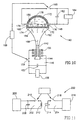
- Apparatus 140 comprises two discharge circuitries, a primary discharge circuitry 146 and an auxiliary discharge circuitry 148.
- Primary discharge circuitry 146 comprises a coil 150, a capacitor battery 152, a switch 154 and a power supply 156.
- Discharge circuitry 148 comprises a DIF device 160, a capacitor battery 162, a power supply 164 and a switch 166. Switches 154 and 166 are controlled by circuitry 168.
- DIF device 160 comprises a chamber 170 defined between rigid wall portions 172 and an elastic wall 174 and accommodating a fluid, which may be a gas or a liquid, and is typically an aqueous solution.
- a fluid which may be a gas or a liquid, and is typically an aqueous solution.
- a plurality of pairs of electrodes 176 are provided and upon closing of switch 166, an electric current is discharged between the electrodes (represented by arrow 178). Such a discharge causes formation of plasma within the fluid which yields a shock wave travelling towards flexible wall 174 (represented by arrows 180).
- Wall 174 is in contact with mechanical waveguide 182 and the shock waves then travels through the waveguide (represented by arrows 184) and condense to yield a higher amplitude shock wave at its tapered end (represented by arrow 186 ).
- FIG. 11 A scheme of an apparatus 200 in accordance with another embodiment of the invention is shown in Fig. 11.
- the apparatus comprises a primary discharge circuitry 202 and an assembly 204.
- Primary discharge circuitry 202 comprises a power supply 206, a capacitor battery 208, a switch 210 and a primary coil 212.
- Assembly 204 comprises an ultrasound energy generating device 214, a power generating device 216 and a switch 218.
- Apparatus 230 comprises a primary discharge circuitry 232 and an assembly 234.
- Primary discharge circuitry 232 comprises a coil 236, a capacitory battery 238, a switch 240 controlled by triggering circuitry 242 and a power supply 244.
- Assembly 234 comprises a power supply 246 and a pair of resistance welding electrodes 248. These electrodes pass current in the direction represented by arrow 250 and as a result of increased resistance at the interface 252 between the two metal objects 254, 256, the interface 252 is heated.
- electrodes 248 are typically cooled by water circulation.
- high welding is achieved by a combination of a PMF and resistance welding processes.
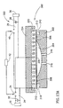
- FIG. 13A An apparatus generally designated 300 for working of a metal plate is shown in Fig. 13A.
- the apparatus comprises a mold 302 with a central inverse dome-shaped recess 304.
- Recess 304 is defined within an annular ridge 306 accommodating an annular groove 308.
- Peripheral of ridge 306 is a shoulder portion 310 defined by an upright wall 312 .
- Defined at the bottom of recess 304 are vertical bores 316.
- the apparatus further comprises a planar forming coil 320 connected to a discharge system 322 and a coil-support member 324.
- Discharge system 322 is in principle similar to the circuitry seen in Fig. 1 and thus functionally like elements have been given like reference numerals and the reader is requested to the description of Fig. 1 for explanations of their function.
- the apparatus holds a metal plate 330 which is to be formed, cut and perforated.
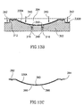
- a superimposed PMF current is generated having, for example, have a shape of the kind shown in Figs. 2A-2C. Consequently, a magnetic pressure is generated which induces rapid movement of portions of plate 330 in the direction represented by arrows 340 and 342 in Fig. 13B. Consequently, the main central portion of the plate is reformed to yield a general shape defined by mold 302.
- the upright walls 312 function essentially as a knife and consequently the plate is cut along a line defined by upright wall 312 yielding a shaped plate 330A, seen separately in Fig. 13C, and a cut-off rim portion 330B.
- the rims of bores 316 act as knives and once the shaped plate 330A impacts the walls of recess 304, a portion 348 corresponding in diameter to the diameter of bore 316 is being cut-off and continues to move rapidly through bore 316 as represented by arrows 350 in Fig. 13B.
- the resulting plate 330A is formed with a central recess 360, a peripheral annular groove 362, with a cut rim 364 and with perforations 366.
Landscapes
- Engineering & Computer Science (AREA)
- Mechanical Engineering (AREA)
- Chemical & Material Sciences (AREA)
- Physics & Mathematics (AREA)
- Fluid Mechanics (AREA)
- Metallurgy (AREA)
- Crystallography & Structural Chemistry (AREA)
- Materials Engineering (AREA)
- Thermal Sciences (AREA)
- Organic Chemistry (AREA)
- Pressure Welding/Diffusion-Bonding (AREA)
- Manufacture And Refinement Of Metals (AREA)
- Superconductors And Manufacturing Methods Therefor (AREA)
- Hard Magnetic Materials (AREA)
- Glass Compositions (AREA)
- Transition And Organic Metals Composition Catalysts For Addition Polymerization (AREA)
Applications Claiming Priority (3)
| Application Number | Priority Date | Filing Date | Title |
|---|---|---|---|
| IL12489998A IL124899A (en) | 1998-06-14 | 1998-06-14 | Apparatus and method for welding of metal objects by a pulsed magnetic force |
| IL12489998 | 1998-06-14 | ||
| PCT/IL1999/000322 WO1999065636A1 (en) | 1998-06-14 | 1999-06-14 | Inducing physical changes in metal objects |
Publications (2)
| Publication Number | Publication Date |
|---|---|
| EP1135234A1 EP1135234A1 (en) | 2001-09-26 |
| EP1135234B1 true EP1135234B1 (en) | 2005-04-20 |
Family
ID=11071620
Family Applications (1)
| Application Number | Title | Priority Date | Filing Date |
|---|---|---|---|
| EP99957031A Expired - Lifetime EP1135234B1 (en) | 1998-06-14 | 1999-06-14 | Inducing physical changes in metal objects |
Country Status (9)
| Country | Link |
|---|---|
| US (1) | US6630649B1 (enExample) |
| EP (1) | EP1135234B1 (enExample) |
| JP (1) | JP4680383B2 (enExample) |
| AT (1) | ATE293512T1 (enExample) |
| AU (1) | AU4287799A (enExample) |
| DE (1) | DE69924872T2 (enExample) |
| ES (1) | ES2242430T3 (enExample) |
| IL (1) | IL124899A (enExample) |
| WO (1) | WO1999065636A1 (enExample) |
Families Citing this family (32)
| Publication number | Priority date | Publication date | Assignee | Title |
|---|---|---|---|---|
| WO2000076685A1 (en) * | 1999-06-14 | 2000-12-21 | Pulsar Welding Ltd. | Electromagnetic and/or electrohydraulic forming of a metal plate |
| MXPA02010588A (es) | 2000-04-26 | 2003-05-14 | Cosma Int Inc | Hidroconformacion de una estructura tubular de diametro variable a partir de una pieza preformada tubular, usando soldadura de impulsos electromagneticos. |
| GB0023296D0 (en) | 2000-09-22 | 2000-11-08 | Rolls Royce Plc | Prestressing of components |
| US20020131572A1 (en) * | 2000-11-02 | 2002-09-19 | Paradis Peter R. | Method and apparatus for scheduling appointments |
| US6910617B2 (en) * | 2002-03-06 | 2005-06-28 | Torque-Traction Technologies, Inc. | Method for securing a yoke to a tube using magnetic pulse welding techniques |
| US6921013B1 (en) * | 2002-04-04 | 2005-07-26 | Dana Corporation | Method and apparatus for performing a magnetic pulse welding operation |
| FR2855775B1 (fr) * | 2003-06-06 | 2007-12-07 | Alain Francois Douarre | Formage, conformation et assemblage de pieces metalliques en coque mince ou en profiles, assistes par vibrations a hautes frequences |
| US6908024B2 (en) * | 2003-08-12 | 2005-06-21 | Dana Corporation | Simultaneous magnetic pulse framing |
| US20070191929A1 (en) * | 2003-08-27 | 2007-08-16 | Cook Incorporated | Medical devices using magnetic pulse welding |
| CN101065210A (zh) * | 2004-11-24 | 2007-10-31 | 达纳公司 | 利用软化第一部件的第一部分的预热步骤实施磁脉冲焊接操作来固定第一和第二金属部件的方法 |
| US20060131877A1 (en) | 2004-12-21 | 2006-06-22 | The Boeing Company | Electromagnetic mechanical pulse forming of fluid joints for high-pressure applications |
| US20060208481A1 (en) * | 2004-12-22 | 2006-09-21 | The Boeing Company | Electromagnetic pulse welding of fluid joints |
| US7513025B2 (en) * | 2004-12-28 | 2009-04-07 | The Boeing Company | Magnetic field concentrator for electromagnetic forming |
| US20060145474A1 (en) * | 2005-01-03 | 2006-07-06 | Allen Fischer | Electromagnetic mechanical pulse forming of fluid joints for low-pressure applications |
| US7378622B2 (en) * | 2006-01-11 | 2008-05-27 | Gateway Engineering, Inc. | System and method for electromagnetic pulse surface treatment |
| US20080041922A1 (en) * | 2006-07-13 | 2008-02-21 | Mariana G Forrest | Hybrid Resistance/Ultrasonic Welding System and Method |
| WO2008113238A1 (fr) * | 2007-03-21 | 2008-09-25 | Wuhan Jingtai Technology Co., Ltd | Procédé accroissant la résistance à l'usure de matériaux métalliques et ses applications |
| US9028164B2 (en) | 2012-03-08 | 2015-05-12 | Dana Automotive Systems Group, Llc | Magnetic pulse formed vehicle driveshaft and method of making same |
| US9021845B2 (en) * | 2012-04-05 | 2015-05-05 | The Ohio State University | Electrically driven rapidly vaporizing foils, wires and strips used for collision welding and sheet metal forming |
| RU2558700C2 (ru) * | 2013-02-25 | 2015-08-10 | Общество С Ограниченной Ответственностью "Саровские Магнитные Технологии" | Устройство и способ для электромагнитной вытяжки и устранения вмятин |
| CN104384698A (zh) * | 2014-11-24 | 2015-03-04 | 天津理工大学 | 一种多物理场辅助异种金属材料电阻焊方法 |
| AT519635B1 (de) * | 2017-02-03 | 2024-04-15 | Miba Gleitlager Austria Gmbh | Verfahren zur Herstellung einer Gleitlagerbuchse |
| US11084122B2 (en) | 2017-07-13 | 2021-08-10 | Ohio State Innovation Foundation | Joining of dissimilar materials using impact welding |
| CN109958710B (zh) * | 2017-12-25 | 2021-09-28 | 米巴精密零部件(中国)有限公司 | 用于滑动轴承套或轴瓦的方法和设备 |
| RU187434U1 (ru) * | 2018-06-06 | 2019-03-06 | федеральное государственное автономное образовательное учреждение высшего образования "Самарский национальный исследовательский университет имени академика С.П. Королева" | Магнитно-импульсная установка с фазо-импульсным управлением зарядом |
| RU187435U1 (ru) * | 2018-06-06 | 2019-03-06 | федеральное государственное автономное образовательное учреждение высшего образования "Самарский национальный исследовательский университет имени академика С.П. Королева" | Многопостовая магнитно-импульсная установка |
| RU187628U1 (ru) * | 2018-08-20 | 2019-03-14 | Юрий Бориславович Кудасов | Устройство электромагнитной вытяжки и устранения вмятин |
| JP7120040B2 (ja) * | 2019-01-21 | 2022-08-17 | マツダ株式会社 | 電磁成形方法および電磁成形装置 |
| CN109946181B (zh) * | 2019-03-18 | 2021-05-14 | 三峡大学 | 一种用于测试金属焊接管件接头冲击强度的装置及方法 |
| CN110283988A (zh) * | 2019-07-03 | 2019-09-27 | 吉林大学 | 一种基于脉冲电流的钢铁材料强韧化新方法 |
| CN111745032B (zh) * | 2020-05-18 | 2021-07-20 | 厦门大学 | 一种基于超声辅助的电磁成形装置及方法 |
| CN114888157B (zh) * | 2022-04-14 | 2024-08-20 | 武汉理工大学 | 电磁超声辅助纤维金属层板冲压变形方法 |
Family Cites Families (20)
| Publication number | Priority date | Publication date | Assignee | Title |
|---|---|---|---|---|
| US3171014A (en) * | 1962-09-05 | 1965-02-23 | Giannini Scient Corp | Method of effecting magnetic deformation of a workpiece |
| US3175383A (en) * | 1963-01-16 | 1965-03-30 | Alfred B Levine | Magnetic processes |
| US3258573A (en) | 1963-06-13 | 1966-06-28 | Theodore J Morin | Welding and forming method and apparatus |
| US3560693A (en) | 1968-06-17 | 1971-02-02 | Ind Magnetics Inc | Magnetic welding and forming |
| US3603759A (en) * | 1970-01-14 | 1971-09-07 | Ind Magnetics Inc | Welding and forming method |
| US3794805A (en) * | 1971-07-02 | 1974-02-26 | W Rudd | Magnetic pulse welding using spaced proximity conductor |
| US3961739A (en) | 1972-04-17 | 1976-06-08 | Grumman Aerospace Corporation | Method of welding metals using stress waves |
| US3998081A (en) | 1974-07-17 | 1976-12-21 | The Boeing Company | Electromagnetic dent puller |
| US4150274A (en) | 1975-11-10 | 1979-04-17 | Minin Vladilen E | Method for lap welding of skelps and device for effecting same |
| JPS5268840A (en) * | 1975-12-05 | 1977-06-08 | Fuedorobuitsuchi Min Urajiiren | Method and device for lap welding tubular steel plate |
| US4135379A (en) | 1976-09-27 | 1979-01-23 | Boeing Commercial Airplane Company | Portable head for electromagnetic pulling |
| KR840002189B1 (ko) | 1980-07-08 | 1984-11-28 | 미쯔비시덴끼 가부시기가이샤 | 펄스 아아크 용접장치 |
| JPS60180624A (ja) * | 1984-02-29 | 1985-09-14 | Agency Of Ind Science & Technol | 金属箔製ドライバを用いた電磁成形法 |
| JPS63115628A (ja) * | 1986-10-31 | 1988-05-20 | Sumitomo Metal Ind Ltd | 電磁成型器 |
| US5495091A (en) | 1989-02-27 | 1996-02-27 | Mitsubishi Denki Kabushiki Kaisha | Pulse welding apparatus |
| US5317116A (en) | 1989-08-02 | 1994-05-31 | Mitsubishi Denki Kabushiki Kaisha | Pulse welding apparatus |
| JP2794126B2 (ja) * | 1989-10-30 | 1998-09-03 | 豊田合成株式会社 | ホース継手の締結方法 |
| WO1997022426A2 (en) * | 1995-12-20 | 1997-06-26 | Pulsar Welding Ltd. | Electromagnetic joining or welding of metal objects |
| IL119679A (en) * | 1996-11-24 | 2001-08-08 | Pulsar Welding Ltd | Electromagnetic forming apparatus |
| US6452139B1 (en) * | 2000-05-01 | 2002-09-17 | Fuel Cell Components And Integrators, Inc. | Method of joining metal components |
-
1998
- 1998-06-14 IL IL12489998A patent/IL124899A/xx not_active IP Right Cessation
-
1999
- 1999-06-14 AT AT99957031T patent/ATE293512T1/de not_active IP Right Cessation
- 1999-06-14 EP EP99957031A patent/EP1135234B1/en not_active Expired - Lifetime
- 1999-06-14 US US09/719,499 patent/US6630649B1/en not_active Expired - Fee Related
- 1999-06-14 AU AU42877/99A patent/AU4287799A/en not_active Abandoned
- 1999-06-14 DE DE69924872T patent/DE69924872T2/de not_active Expired - Fee Related
- 1999-06-14 WO PCT/IL1999/000322 patent/WO1999065636A1/en not_active Ceased
- 1999-06-14 JP JP2000554498A patent/JP4680383B2/ja not_active Expired - Fee Related
- 1999-06-14 ES ES99957031T patent/ES2242430T3/es not_active Expired - Lifetime
Also Published As
| Publication number | Publication date |
|---|---|
| US6630649B1 (en) | 2003-10-07 |
| DE69924872D1 (de) | 2005-05-25 |
| ATE293512T1 (de) | 2005-05-15 |
| IL124899A (en) | 2003-03-12 |
| AU4287799A (en) | 2000-01-05 |
| JP4680383B2 (ja) | 2011-05-11 |
| ES2242430T3 (es) | 2005-11-01 |
| JP2002518180A (ja) | 2002-06-25 |
| EP1135234A1 (en) | 2001-09-26 |
| IL124899A0 (en) | 1999-01-26 |
| DE69924872T2 (de) | 2006-09-28 |
| WO1999065636A1 (en) | 1999-12-23 |
Similar Documents
| Publication | Publication Date | Title |
|---|---|---|
| EP1135234B1 (en) | Inducing physical changes in metal objects | |
| EP0955911B1 (en) | Device for the comminution of concretions | |
| JP3078231B2 (ja) | 超音波振動接合装置 | |
| US6708542B1 (en) | Electromagnetic and/or electrohydraulic forming of a metal plate | |
| US5117088A (en) | Device and method for starting electric arc of a welder | |
| EP0822590A3 (en) | Method and apparatus for releasing a workpiece from an electrostatic chuck | |
| EP1054745A2 (en) | Method and apparatus for pulsed discharge forming of a dish from a planar plate | |
| US20110088802A1 (en) | Liquid Arc Induced Cavitation (LAIC) System | |
| WO1998007520A1 (fr) | Procede de cassure grace au choc d'une decharge electrique et appareil s'y rapportant | |
| US4379960A (en) | Electrical discharge machining method and apparatus using ultrasonic waves and magnetic energy applied concurrently to the machining gap | |
| CN114260576B (zh) | 一种超声辅助空心钨极gta-激光同轴复合焊接系统 | |
| ES2138257T3 (es) | Procedimiento para encender un arco voltaico de soldadura. | |
| CA2397271A1 (en) | Method for transferring molecules in cells | |
| RU97113387A (ru) | Устройство для стимуляции метаболизма тканей ударно-волновыми импульсами | |
| EP2512747A1 (de) | Handwerkzeug mit einem gegenschwinger | |
| JP2004158247A (ja) | プラズマ処理装置およびプラズマ処理方法 | |
| KR102065434B1 (ko) | 액중 방전에 의한 전자기 피닝장치 | |
| CN112180432A (zh) | 一种基于电晕放电的高效率电火花震源系统及设置方法 | |
| US20210338259A1 (en) | Combined shockwave and ultrasound source | |
| US3236996A (en) | Welding apparatus | |
| JP2005026063A (ja) | プラズマ処理装置およびプラズマ処理方法 | |
| RU2003748C1 (ru) | Бытова стиральна машина вибрационного типа | |
| KR102377259B1 (ko) | 압전식 체외충격파와 레이저의 복합 발생장치 및 이를 포함하는 복합 치료장치 | |
| WANG et al. | Ultrasonic Peening Equipment Used for Improring Fatigue Strength of Welded Joints | |
| GB2040725A (en) | Improvements in or relating to methods of and apparatuses for disintegrating materials |
Legal Events
| Date | Code | Title | Description |
|---|---|---|---|
| PUAI | Public reference made under article 153(3) epc to a published international application that has entered the european phase |
Free format text: ORIGINAL CODE: 0009012 |
|
| 17P | Request for examination filed |
Effective date: 20001230 |
|
| AK | Designated contracting states |
Kind code of ref document: A1 Designated state(s): AT BE CH CY DE DK ES FI FR GB GR IE IT LI LU MC NL PT SE |
|
| 17Q | First examination report despatched |
Effective date: 20030515 |
|
| GRAP | Despatch of communication of intention to grant a patent |
Free format text: ORIGINAL CODE: EPIDOSNIGR1 |
|
| GRAS | Grant fee paid |
Free format text: ORIGINAL CODE: EPIDOSNIGR3 |
|
| GRAA | (expected) grant |
Free format text: ORIGINAL CODE: 0009210 |
|
| AK | Designated contracting states |
Kind code of ref document: B1 Designated state(s): AT BE CH CY DE DK ES FI FR GB GR IE IT LI LU MC NL PT SE |
|
| PG25 | Lapsed in a contracting state [announced via postgrant information from national office to epo] |
Ref country code: NL Free format text: LAPSE BECAUSE OF FAILURE TO SUBMIT A TRANSLATION OF THE DESCRIPTION OR TO PAY THE FEE WITHIN THE PRESCRIBED TIME-LIMIT Effective date: 20050420 Ref country code: LI Free format text: LAPSE BECAUSE OF FAILURE TO SUBMIT A TRANSLATION OF THE DESCRIPTION OR TO PAY THE FEE WITHIN THE PRESCRIBED TIME-LIMIT Effective date: 20050420 Ref country code: IT Free format text: LAPSE BECAUSE OF FAILURE TO SUBMIT A TRANSLATION OF THE DESCRIPTION OR TO PAY THE FEE WITHIN THE PRESCRIBED TIME-LIMIT;WARNING: LAPSES OF ITALIAN PATENTS WITH EFFECTIVE DATE BEFORE 2007 MAY HAVE OCCURRED AT ANY TIME BEFORE 2007. THE CORRECT EFFECTIVE DATE MAY BE DIFFERENT FROM THE ONE RECORDED. Effective date: 20050420 Ref country code: FI Free format text: LAPSE BECAUSE OF FAILURE TO SUBMIT A TRANSLATION OF THE DESCRIPTION OR TO PAY THE FEE WITHIN THE PRESCRIBED TIME-LIMIT Effective date: 20050420 Ref country code: CH Free format text: LAPSE BECAUSE OF FAILURE TO SUBMIT A TRANSLATION OF THE DESCRIPTION OR TO PAY THE FEE WITHIN THE PRESCRIBED TIME-LIMIT Effective date: 20050420 Ref country code: BE Free format text: LAPSE BECAUSE OF FAILURE TO SUBMIT A TRANSLATION OF THE DESCRIPTION OR TO PAY THE FEE WITHIN THE PRESCRIBED TIME-LIMIT Effective date: 20050420 Ref country code: AT Free format text: LAPSE BECAUSE OF FAILURE TO SUBMIT A TRANSLATION OF THE DESCRIPTION OR TO PAY THE FEE WITHIN THE PRESCRIBED TIME-LIMIT Effective date: 20050420 |
|
| REG | Reference to a national code |
Ref country code: GB Ref legal event code: FG4D |
|
| REG | Reference to a national code |
Ref country code: CH Ref legal event code: EP |
|
| REG | Reference to a national code |
Ref country code: IE Ref legal event code: FG4D |
|
| REF | Corresponds to: |
Ref document number: 69924872 Country of ref document: DE Date of ref document: 20050525 Kind code of ref document: P |
|
| PG25 | Lapsed in a contracting state [announced via postgrant information from national office to epo] |
Ref country code: LU Free format text: LAPSE BECAUSE OF NON-PAYMENT OF DUE FEES Effective date: 20050614 Ref country code: IE Free format text: LAPSE BECAUSE OF NON-PAYMENT OF DUE FEES Effective date: 20050614 Ref country code: CY Free format text: LAPSE BECAUSE OF FAILURE TO SUBMIT A TRANSLATION OF THE DESCRIPTION OR TO PAY THE FEE WITHIN THE PRESCRIBED TIME-LIMIT Effective date: 20050614 |
|
| PG25 | Lapsed in a contracting state [announced via postgrant information from national office to epo] |
Ref country code: MC Free format text: LAPSE BECAUSE OF NON-PAYMENT OF DUE FEES Effective date: 20050630 |
|
| PG25 | Lapsed in a contracting state [announced via postgrant information from national office to epo] |
Ref country code: SE Free format text: LAPSE BECAUSE OF FAILURE TO SUBMIT A TRANSLATION OF THE DESCRIPTION OR TO PAY THE FEE WITHIN THE PRESCRIBED TIME-LIMIT Effective date: 20050720 Ref country code: GR Free format text: LAPSE BECAUSE OF FAILURE TO SUBMIT A TRANSLATION OF THE DESCRIPTION OR TO PAY THE FEE WITHIN THE PRESCRIBED TIME-LIMIT Effective date: 20050720 Ref country code: DK Free format text: LAPSE BECAUSE OF FAILURE TO SUBMIT A TRANSLATION OF THE DESCRIPTION OR TO PAY THE FEE WITHIN THE PRESCRIBED TIME-LIMIT Effective date: 20050720 |
|
| PG25 | Lapsed in a contracting state [announced via postgrant information from national office to epo] |
Ref country code: DE Free format text: LAPSE BECAUSE OF FAILURE TO SUBMIT A TRANSLATION OF THE DESCRIPTION OR TO PAY THE FEE WITHIN THE PRESCRIBED TIME-LIMIT Effective date: 20050721 |
|
| PG25 | Lapsed in a contracting state [announced via postgrant information from national office to epo] |
Ref country code: PT Free format text: LAPSE BECAUSE OF FAILURE TO SUBMIT A TRANSLATION OF THE DESCRIPTION OR TO PAY THE FEE WITHIN THE PRESCRIBED TIME-LIMIT Effective date: 20050920 |
|
| REG | Reference to a national code |
Ref country code: CH Ref legal event code: PL |
|
| NLV1 | Nl: lapsed or annulled due to failure to fulfill the requirements of art. 29p and 29m of the patents act | ||
| REG | Reference to a national code |
Ref country code: ES Ref legal event code: FG2A Ref document number: 2242430 Country of ref document: ES Kind code of ref document: T3 |
|
| PLBE | No opposition filed within time limit |
Free format text: ORIGINAL CODE: 0009261 |
|
| STAA | Information on the status of an ep patent application or granted ep patent |
Free format text: STATUS: NO OPPOSITION FILED WITHIN TIME LIMIT |
|
| REG | Reference to a national code |
Ref country code: IE Ref legal event code: MM4A |
|
| ET | Fr: translation filed | ||
| 26N | No opposition filed |
Effective date: 20060123 |
|
| PGFP | Annual fee paid to national office [announced via postgrant information from national office to epo] |
Ref country code: ES Payment date: 20080717 Year of fee payment: 10 Ref country code: DE Payment date: 20080619 Year of fee payment: 10 |
|
| PGFP | Annual fee paid to national office [announced via postgrant information from national office to epo] |
Ref country code: FR Payment date: 20080617 Year of fee payment: 10 |
|
| PGFP | Annual fee paid to national office [announced via postgrant information from national office to epo] |
Ref country code: GB Payment date: 20080618 Year of fee payment: 10 |
|
| GBPC | Gb: european patent ceased through non-payment of renewal fee |
Effective date: 20090614 |
|
| REG | Reference to a national code |
Ref country code: FR Ref legal event code: ST Effective date: 20100226 |
|
| PG25 | Lapsed in a contracting state [announced via postgrant information from national office to epo] |
Ref country code: FR Free format text: LAPSE BECAUSE OF NON-PAYMENT OF DUE FEES Effective date: 20090630 |
|
| PG25 | Lapsed in a contracting state [announced via postgrant information from national office to epo] |
Ref country code: GB Free format text: LAPSE BECAUSE OF NON-PAYMENT OF DUE FEES Effective date: 20090614 |
|
| PG25 | Lapsed in a contracting state [announced via postgrant information from national office to epo] |
Ref country code: DE Free format text: LAPSE BECAUSE OF NON-PAYMENT OF DUE FEES Effective date: 20100101 |
|
| REG | Reference to a national code |
Ref country code: ES Ref legal event code: FD2A Effective date: 20090615 |
|
| PG25 | Lapsed in a contracting state [announced via postgrant information from national office to epo] |
Ref country code: ES Free format text: LAPSE BECAUSE OF NON-PAYMENT OF DUE FEES Effective date: 20090615 |