EP1135203B1 - Vorrichtung zur bereitstellung eines blockflansches einer mannlochöffnung od. dgl., insbesondere bei wirbelschichtreaktoren - Google Patents
Vorrichtung zur bereitstellung eines blockflansches einer mannlochöffnung od. dgl., insbesondere bei wirbelschichtreaktoren Download PDFInfo
- Publication number
- EP1135203B1 EP1135203B1 EP99953912A EP99953912A EP1135203B1 EP 1135203 B1 EP1135203 B1 EP 1135203B1 EP 99953912 A EP99953912 A EP 99953912A EP 99953912 A EP99953912 A EP 99953912A EP 1135203 B1 EP1135203 B1 EP 1135203B1
- Authority
- EP
- European Patent Office
- Prior art keywords
- flange
- reactor
- providing
- loose flange
- manhole opening
- Prior art date
- Legal status (The legal status is an assumption and is not a legal conclusion. Google has not performed a legal analysis and makes no representation as to the accuracy of the status listed.)
- Expired - Lifetime
Links
- VEXZGXHMUGYJMC-UHFFFAOYSA-N Hydrochloric acid Chemical compound Cl VEXZGXHMUGYJMC-UHFFFAOYSA-N 0.000 claims abstract description 7
- VGGSQFUCUMXWEO-UHFFFAOYSA-N Ethene Chemical compound C=C VGGSQFUCUMXWEO-UHFFFAOYSA-N 0.000 claims abstract description 4
- 239000005977 Ethylene Substances 0.000 claims abstract description 4
- QVGXLLKOCUKJST-UHFFFAOYSA-N atomic oxygen Chemical compound [O] QVGXLLKOCUKJST-UHFFFAOYSA-N 0.000 claims abstract description 4
- 230000005484 gravity Effects 0.000 claims abstract description 4
- IXCSERBJSXMMFS-UHFFFAOYSA-N hydrogen chloride Substances Cl.Cl IXCSERBJSXMMFS-UHFFFAOYSA-N 0.000 claims abstract description 4
- 229910052760 oxygen Inorganic materials 0.000 claims abstract description 4
- 239000001301 oxygen Substances 0.000 claims abstract description 4
- 238000010276 construction Methods 0.000 claims 1
- 230000002093 peripheral effect Effects 0.000 claims 1
- 239000003054 catalyst Substances 0.000 description 4
- 239000000463 material Substances 0.000 description 3
- WSLDOOZREJYCGB-UHFFFAOYSA-N 1,2-Dichloroethane Chemical compound ClCCCl WSLDOOZREJYCGB-UHFFFAOYSA-N 0.000 description 1
- RYGMFSIKBFXOCR-UHFFFAOYSA-N Copper Chemical compound [Cu] RYGMFSIKBFXOCR-UHFFFAOYSA-N 0.000 description 1
- 229910052802 copper Inorganic materials 0.000 description 1
- 239000010949 copper Substances 0.000 description 1
- 230000007797 corrosion Effects 0.000 description 1
- 238000005260 corrosion Methods 0.000 description 1
- 230000006735 deficit Effects 0.000 description 1
- 238000011010 flushing procedure Methods 0.000 description 1
- 238000005259 measurement Methods 0.000 description 1
- 210000002445 nipple Anatomy 0.000 description 1
- 239000000523 sample Substances 0.000 description 1
- 230000007704 transition Effects 0.000 description 1
- XLYOFNOQVPJJNP-UHFFFAOYSA-N water Substances O XLYOFNOQVPJJNP-UHFFFAOYSA-N 0.000 description 1
Images

Classifications
-
- B—PERFORMING OPERATIONS; TRANSPORTING
- B01—PHYSICAL OR CHEMICAL PROCESSES OR APPARATUS IN GENERAL
- B01J—CHEMICAL OR PHYSICAL PROCESSES, e.g. CATALYSIS OR COLLOID CHEMISTRY; THEIR RELEVANT APPARATUS
- B01J8/00—Chemical or physical processes in general, conducted in the presence of fluids and solid particles; Apparatus for such processes
- B01J8/18—Chemical or physical processes in general, conducted in the presence of fluids and solid particles; Apparatus for such processes with fluidised particles
- B01J8/1872—Details of the fluidised bed reactor
-
- B—PERFORMING OPERATIONS; TRANSPORTING
- B01—PHYSICAL OR CHEMICAL PROCESSES OR APPARATUS IN GENERAL
- B01J—CHEMICAL OR PHYSICAL PROCESSES, e.g. CATALYSIS OR COLLOID CHEMISTRY; THEIR RELEVANT APPARATUS
- B01J8/00—Chemical or physical processes in general, conducted in the presence of fluids and solid particles; Apparatus for such processes
- B01J8/0015—Feeding of the particles in the reactor; Evacuation of the particles out of the reactor
- B01J8/003—Feeding of the particles in the reactor; Evacuation of the particles out of the reactor in a downward flow
-
- C—CHEMISTRY; METALLURGY
- C07—ORGANIC CHEMISTRY
- C07C—ACYCLIC OR CARBOCYCLIC COMPOUNDS
- C07C17/00—Preparation of halogenated hydrocarbons
- C07C17/093—Preparation of halogenated hydrocarbons by replacement by halogens
- C07C17/15—Preparation of halogenated hydrocarbons by replacement by halogens with oxygen as auxiliary reagent, e.g. oxychlorination
- C07C17/152—Preparation of halogenated hydrocarbons by replacement by halogens with oxygen as auxiliary reagent, e.g. oxychlorination of hydrocarbons
- C07C17/156—Preparation of halogenated hydrocarbons by replacement by halogens with oxygen as auxiliary reagent, e.g. oxychlorination of hydrocarbons of unsaturated hydrocarbons
Definitions
- the invention is directed to a block flange Manhole opening or the like.
- a block flange Manhole opening or the like For fluidized bed reactors for Oxichioration of ethylene, oxygen and HCl with an in the wall flange attached to the reactor wall.
- oxychlorination In the so-called oxychlorination, ethylene, oxygen and HCl in a fluidized bed reactor (oxi reactor) a copper-containing catalyst to 1,2-dichloroethane and Implemented water. Inside the reactor can operate and when the system is turned off, catalyst deposits in all Dead dreams occur. The presence of HCl leads when falling below the dew point to form hydrochloric acid and thus severe corrosion. Are particularly at risk Dead spaces in the coat area, like all manholes and all Test nipple. An attempt has been made to remedy this disadvantage by that, for example, heated in all measuring spouts Flush lines are provided to also have an impairment the measurements and the dew point undershoot there to avoid.
- the object of the invention is to provide a solution with all of these additional relief measures are unnecessary and the associated effort can be saved, without the functionality of the system suffering and without the unwanted deposits in these Areas occur.
- the invention in the case of an annular flange also provides for the bevel the area of the horizontal central plane in Inner edge area beginning at the vertical center of the Flange ring is designed to enlarge.
- This design results in a smooth, homogeneous, funnel-shaped slide that points inwards to the reactor, so that, for example, when switching off and sinking the fluidized bed a deposit of catalyst material or the like. is prevented with certainty.
- Block flange according to the invention in a reactor wall 2 shrink wrapped.
- the block flange has a certain cylindrical Extension and has a passage opening 3, e.g. for a measuring device, a probe or the like.
- Fig. 2 In his facing towards the inside, designated in Fig. 2 with 2a
- the area of the inner flange 4 is chamfered Bevel is denoted by 5 in FIG. 1.
- This beveled Area 5 begins approximately in the middle horizontal 6 of the flange 1, runs to the horizontal center, with 7 referred to the flange and from there again to vertical center 6, so that there is a kind of chute. Any material noticeable there is automatically dropped by gravity.
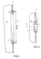
- Fig. 2 is a manhole training, here is one too appropriate flange design provided, the manhole is closed with a lid labeled 8 there.
- FIG. 3 such a block flange 1 is shown in section.
- the described embodiments of the Invention to change in many ways without the To leave basic ideas.
- the flanges 1 or 1a in particular with the inner wall surface of the reactor wall 2 be welded in flush the flange or the flange bore 3 may be in a downward facing minor Angles must be arranged to prevent striking material to reinforce u.
- the flanges 1 or 1a in particular with the inner wall surface of the reactor wall 2 be welded in flush, the flange or the flange bore 3 may be in a downward facing minor Angles must be arranged to prevent striking material to reinforce u.
- the flanges 1 or 1a in particular with the inner wall surface of the reactor wall 2 be welded in flush the flange or the flange bore 3 may be in a downward facing minor
Landscapes
- Chemical & Material Sciences (AREA)
- Organic Chemistry (AREA)
- Chemical Kinetics & Catalysis (AREA)
- Engineering & Computer Science (AREA)
- Combustion & Propulsion (AREA)
- Devices And Processes Conducted In The Presence Of Fluids And Solid Particles (AREA)
- Organic Low-Molecular-Weight Compounds And Preparation Thereof (AREA)
- Low-Molecular Organic Synthesis Reactions Using Catalysts (AREA)
- Underground Structures, Protecting, Testing And Restoring Foundations (AREA)
Description
- Fig. 1
- eine vereinfachte räumliche Darstellung eines Blockflansches nach der Erfindung,
- Fig. 2
- eine vereinfachte Schnittdarstellung eines Mannloches sowie in
- Fig. 3
- eine vereinfachte Schnittdarstellung eines Blockflansches etwa gemäß Fig. 1.
Claims (2)
- Blockflansch einer Mannlochöffnung od. dgl. für Wirbelschichtreaktoren zur Oxichlorierung von Ethylen, Sauerstoff und HCl mit einem in der vertikalen Reaktorwand befestigten Wandflansch,
dadurch gekennzeichnet, daß die in das Reaktorinnere und in Schwerkraftrichtung untere Flanschfläche (5) wenigstens bereichsweise angeschrägt ausgebildet ist. - Blockflansch nach Anspruch 1, wobei der Flansch ringförmig ausgebildet ist,
dadurch gekennzeichnet, daß die Abschrägung der Fläche (5) von der horizontalen Mittelebene (6) im Innenrandbereich beginnend zur vertikalen Mitte (7) des Flanschringes sich vergrößernd ausgebildet ist.
Applications Claiming Priority (3)
| Application Number | Priority Date | Filing Date | Title |
|---|---|---|---|
| DE19851423A DE19851423A1 (de) | 1998-11-07 | 1998-11-07 | Vorrichtung zur Bereitstellung eines Blockflansches einer Mannlochöffnung o. dgl., insbesondere bei Wirbelschichtreaktoren |
| DE19851423 | 1998-11-07 | ||
| PCT/EP1999/008001 WO2000027517A1 (de) | 1998-11-07 | 1999-10-21 | Vorrichtung zur bereitstellung eines blockflansches einer mannlochöffnung od. dgl., insbesondere bei wirbelschichtreaktoren |
Publications (2)
| Publication Number | Publication Date |
|---|---|
| EP1135203A1 EP1135203A1 (de) | 2001-09-26 |
| EP1135203B1 true EP1135203B1 (de) | 2002-06-05 |
Family
ID=7887048
Family Applications (1)
| Application Number | Title | Priority Date | Filing Date |
|---|---|---|---|
| EP99953912A Expired - Lifetime EP1135203B1 (de) | 1998-11-07 | 1999-10-21 | Vorrichtung zur bereitstellung eines blockflansches einer mannlochöffnung od. dgl., insbesondere bei wirbelschichtreaktoren |
Country Status (8)
| Country | Link |
|---|---|
| US (2) | US7285249B2 (de) |
| EP (1) | EP1135203B1 (de) |
| JP (1) | JP4632542B2 (de) |
| AT (1) | ATE218393T1 (de) |
| AU (1) | AU1042400A (de) |
| DE (2) | DE19851423A1 (de) |
| NO (1) | NO321312B1 (de) |
| WO (1) | WO2000027517A1 (de) |
Cited By (1)
| Publication number | Priority date | Publication date | Assignee | Title |
|---|---|---|---|---|
| DE102018003340A1 (de) | 2018-04-24 | 2019-10-24 | Linde Aktiengesellschaft | Vermeidung von Korrosionsschäden an Isothermreaktoren |
Families Citing this family (3)
| Publication number | Priority date | Publication date | Assignee | Title |
|---|---|---|---|---|
| JP6372086B2 (ja) * | 2014-01-28 | 2018-08-15 | 三菱ケミカル株式会社 | 流動床反応器及びそれを用いたニトリル化合物の製造方法 |
| JP6486015B2 (ja) * | 2014-04-25 | 2019-03-20 | 三菱ケミカル株式会社 | 流動床反応器 |
| JP2019126759A (ja) * | 2018-01-23 | 2019-08-01 | 旭化成株式会社 | 接続構造及び流動層反応装置。 |
Family Cites Families (5)
| Publication number | Priority date | Publication date | Assignee | Title |
|---|---|---|---|---|
| US4074691A (en) * | 1976-07-01 | 1978-02-21 | Exxon Research & Engineering Co. | Open shroud trickle valve |
| ES468300A1 (es) * | 1977-04-28 | 1978-11-16 | Hoechst Ag | Procedimiento para la preparacion de 1,2-dicloroetano. |
| US4203686A (en) * | 1978-07-17 | 1980-05-20 | Bowman Harold M | Manhole construction |
| EP0026057B1 (de) * | 1979-09-14 | 1984-03-14 | Imperial Chemical Industries Plc | Synthesereaktor und Verfahren |
| AT400368B (de) * | 1991-12-09 | 1995-12-27 | Huemer E Unistrap Verpackung | Dosierverfahren und vorrichtung zu dessen durchführung |
-
1998
- 1998-11-07 DE DE19851423A patent/DE19851423A1/de not_active Withdrawn
-
1999
- 1999-10-21 EP EP99953912A patent/EP1135203B1/de not_active Expired - Lifetime
- 1999-10-21 WO PCT/EP1999/008001 patent/WO2000027517A1/de not_active Ceased
- 1999-10-21 JP JP2000580737A patent/JP4632542B2/ja not_active Expired - Lifetime
- 1999-10-21 AT AT99953912T patent/ATE218393T1/de not_active IP Right Cessation
- 1999-10-21 DE DE59901678T patent/DE59901678D1/de not_active Expired - Lifetime
- 1999-10-21 AU AU10424/00A patent/AU1042400A/en not_active Abandoned
-
2001
- 2001-05-04 NO NO20012225A patent/NO321312B1/no not_active IP Right Cessation
-
2004
- 2004-10-27 US US10/976,287 patent/US7285249B2/en not_active Expired - Lifetime
-
2005
- 2005-03-15 US US09/849,678 patent/US20060024214A1/en not_active Abandoned
Cited By (1)
| Publication number | Priority date | Publication date | Assignee | Title |
|---|---|---|---|---|
| DE102018003340A1 (de) | 2018-04-24 | 2019-10-24 | Linde Aktiengesellschaft | Vermeidung von Korrosionsschäden an Isothermreaktoren |
Also Published As
| Publication number | Publication date |
|---|---|
| DE59901678D1 (de) | 2002-07-11 |
| US20050058580A1 (en) | 2005-03-17 |
| US20060024214A1 (en) | 2006-02-02 |
| JP2002529222A (ja) | 2002-09-10 |
| NO20012225D0 (no) | 2001-05-04 |
| DE19851423A1 (de) | 2000-05-11 |
| WO2000027517A1 (de) | 2000-05-18 |
| AU1042400A (en) | 2000-05-29 |
| ATE218393T1 (de) | 2002-06-15 |
| US7285249B2 (en) | 2007-10-23 |
| JP4632542B2 (ja) | 2011-02-16 |
| NO321312B1 (no) | 2006-04-24 |
| EP1135203A1 (de) | 2001-09-26 |
| NO20012225L (no) | 2001-05-04 |
Similar Documents
| Publication | Publication Date | Title |
|---|---|---|
| DE2940933C2 (de) | Kühlring für eine Tauchrohrbaugruppe eines Reaktionsbehälters | |
| DE69611929T2 (de) | Einfülleinrichtung für lagerbehälter | |
| DE102015112911A1 (de) | Spülkastenanordnung mit veränderbarem Spülstrom | |
| WO2000027517A1 (de) | Vorrichtung zur bereitstellung eines blockflansches einer mannlochöffnung od. dgl., insbesondere bei wirbelschichtreaktoren | |
| DE19515951A1 (de) | Wasserprobenehmer | |
| EP0531660B1 (de) | Führungseinrichtung für ein Tauchrührwerk | |
| DE3112702A1 (de) | Hubeinrichtung fuer eine offshore-konstruktion | |
| EP3732962A1 (de) | Köderstation mit luftkammer | |
| DE4291643C2 (de) | Vorrichtung zum Verhindern des Eindringens von Tieren, insbesondere Ratten, in ein Rohrnetzwerk | |
| EP1006243A1 (de) | Anschlussblock für Sanitärarmaturen | |
| DE102016122662A1 (de) | Fischlift, Zuflusseinrichtung für einen Fischlift und Verfahren zum Betrieb eines Fischlifts | |
| EP3351698A9 (de) | Ablaufarmatur | |
| DE1952491A1 (de) | Wirbelschichtbettreaktor | |
| EP0655536A1 (de) | Vorrichtung zum Zurückhalten von Ratten oder dgl. in einer Abwasserleitung | |
| EP0728548B1 (de) | Schmelzbehälter und diesen verwendende Schmelzvorrichtung | |
| DE9307950U1 (de) | Einrichtung zur Verhinderung des Aufsteigens von Ungeziefer, vor allem Ratten, in Steigleitungen, Abwasserrohren u.dgl. | |
| DE2264384A1 (de) | Greifer zum gebrauch fuer einen kernreaktor | |
| DE19953656A1 (de) | Vorrichtung zum Ausgleich des Drucks einer Flüssigkeit und Verfahren zur Änderung des Druckausgleichsverhältnisses | |
| DE2552082B1 (de) | Kontrollvorrichtung fuer die wasserqualitaet | |
| DE19719217C2 (de) | Reinigungsverschluß für Entwässerungsleitungen | |
| DE102404C (de) | ||
| DE2215703A1 (de) | Vorrichtung zum Abstreifen von Natrium an einem zylindrischen Stab | |
| DE2429411A1 (de) | Kabelverlegevorrichtung | |
| DE3110734A1 (de) | Rohranschluss, insbesondere fuer hebeanlagen-sammelbehaelter | |
| EP1174691B1 (de) | Durchflussmess- und Anzeigeeinrichtung |
Legal Events
| Date | Code | Title | Description |
|---|---|---|---|
| PUAI | Public reference made under article 153(3) epc to a published international application that has entered the european phase |
Free format text: ORIGINAL CODE: 0009012 |
|
| 17P | Request for examination filed |
Effective date: 20010222 |
|
| AK | Designated contracting states |
Kind code of ref document: A1 Designated state(s): AT BE CH CY DE DK ES FI FR GB GR IE IT LI LU MC NL PT SE |
|
| 17Q | First examination report despatched |
Effective date: 20011001 |
|
| GRAG | Despatch of communication of intention to grant |
Free format text: ORIGINAL CODE: EPIDOS AGRA |
|
| GRAG | Despatch of communication of intention to grant |
Free format text: ORIGINAL CODE: EPIDOS AGRA |
|
| GRAH | Despatch of communication of intention to grant a patent |
Free format text: ORIGINAL CODE: EPIDOS IGRA |
|
| GRAH | Despatch of communication of intention to grant a patent |
Free format text: ORIGINAL CODE: EPIDOS IGRA |
|
| GRAA | (expected) grant |
Free format text: ORIGINAL CODE: 0009210 |
|
| AK | Designated contracting states |
Kind code of ref document: B1 Designated state(s): AT BE CH CY DE DK ES FI FR GB GR IE IT LI LU MC NL PT SE |
|
| PG25 | Lapsed in a contracting state [announced via postgrant information from national office to epo] |
Ref country code: IE Free format text: LAPSE BECAUSE OF FAILURE TO SUBMIT A TRANSLATION OF THE DESCRIPTION OR TO PAY THE FEE WITHIN THE PRESCRIBED TIME-LIMIT Effective date: 20020605 Ref country code: GR Free format text: LAPSE BECAUSE OF FAILURE TO SUBMIT A TRANSLATION OF THE DESCRIPTION OR TO PAY THE FEE WITHIN THE PRESCRIBED TIME-LIMIT Effective date: 20020605 Ref country code: FI Free format text: LAPSE BECAUSE OF FAILURE TO SUBMIT A TRANSLATION OF THE DESCRIPTION OR TO PAY THE FEE WITHIN THE PRESCRIBED TIME-LIMIT Effective date: 20020605 |
|
| REF | Corresponds to: |
Ref document number: 218393 Country of ref document: AT Date of ref document: 20020615 Kind code of ref document: T |
|
| REG | Reference to a national code |
Ref country code: GB Ref legal event code: FG4D Free format text: NOT ENGLISH |
|
| REG | Reference to a national code |
Ref country code: CH Ref legal event code: EP |
|
| REG | Reference to a national code |
Ref country code: IE Ref legal event code: FG4D Free format text: GERMAN |
|
| REF | Corresponds to: |
Ref document number: 59901678 Country of ref document: DE Date of ref document: 20020711 |
|
| GBT | Gb: translation of ep patent filed (gb section 77(6)(a)/1977) |
Effective date: 20020721 |
|
| PG25 | Lapsed in a contracting state [announced via postgrant information from national office to epo] |
Ref country code: SE Free format text: LAPSE BECAUSE OF FAILURE TO SUBMIT A TRANSLATION OF THE DESCRIPTION OR TO PAY THE FEE WITHIN THE PRESCRIBED TIME-LIMIT Effective date: 20020905 Ref country code: PT Free format text: LAPSE BECAUSE OF FAILURE TO SUBMIT A TRANSLATION OF THE DESCRIPTION OR TO PAY THE FEE WITHIN THE PRESCRIBED TIME-LIMIT Effective date: 20020905 Ref country code: DK Free format text: LAPSE BECAUSE OF FAILURE TO SUBMIT A TRANSLATION OF THE DESCRIPTION OR TO PAY THE FEE WITHIN THE PRESCRIBED TIME-LIMIT Effective date: 20020905 |
|
| RAP2 | Party data changed (patent owner data changed or rights of a patent transferred) |
Owner name: UHDE GMBH |
|
| PG25 | Lapsed in a contracting state [announced via postgrant information from national office to epo] |
Ref country code: LU Free format text: LAPSE BECAUSE OF NON-PAYMENT OF DUE FEES Effective date: 20021021 Ref country code: AT Free format text: LAPSE BECAUSE OF NON-PAYMENT OF DUE FEES Effective date: 20021021 |
|
| PG25 | Lapsed in a contracting state [announced via postgrant information from national office to epo] |
Ref country code: CY Free format text: LAPSE BECAUSE OF FAILURE TO SUBMIT A TRANSLATION OF THE DESCRIPTION OR TO PAY THE FEE WITHIN THE PRESCRIBED TIME-LIMIT Effective date: 20021031 |
|
| NLT2 | Nl: modifications (of names), taken from the european patent patent bulletin |
Owner name: UHDE GMBH |
|
| ET | Fr: translation filed | ||
| PG25 | Lapsed in a contracting state [announced via postgrant information from national office to epo] |
Ref country code: ES Free format text: LAPSE BECAUSE OF FAILURE TO SUBMIT A TRANSLATION OF THE DESCRIPTION OR TO PAY THE FEE WITHIN THE PRESCRIBED TIME-LIMIT Effective date: 20021220 |
|
| BECN | Be: change of holder's name |
Effective date: 20020605 |
|
| NLT1 | Nl: modifications of names registered in virtue of documents presented to the patent office pursuant to art. 16 a, paragraph 1 |
Owner name: UHDE GMBH |
|
| REG | Reference to a national code |
Ref country code: IE Ref legal event code: FD4D Ref document number: 1135203E Country of ref document: IE |
|
| PLBE | No opposition filed within time limit |
Free format text: ORIGINAL CODE: 0009261 |
|
| STAA | Information on the status of an ep patent application or granted ep patent |
Free format text: STATUS: NO OPPOSITION FILED WITHIN TIME LIMIT |
|
| PG25 | Lapsed in a contracting state [announced via postgrant information from national office to epo] |
Ref country code: MC Free format text: LAPSE BECAUSE OF NON-PAYMENT OF DUE FEES Effective date: 20030501 |
|
| 26N | No opposition filed |
Effective date: 20030306 |
|
| PG25 | Lapsed in a contracting state [announced via postgrant information from national office to epo] |
Ref country code: LI Free format text: LAPSE BECAUSE OF NON-PAYMENT OF DUE FEES Effective date: 20031031 Ref country code: CH Free format text: LAPSE BECAUSE OF NON-PAYMENT OF DUE FEES Effective date: 20031031 |
|
| REG | Reference to a national code |
Ref country code: CH Ref legal event code: PL |
|
| PGFP | Annual fee paid to national office [announced via postgrant information from national office to epo] |
Ref country code: NL Payment date: 20131022 Year of fee payment: 15 Ref country code: IT Payment date: 20131024 Year of fee payment: 15 |
|
| REG | Reference to a national code |
Ref country code: DE Ref legal event code: R082 Ref document number: 59901678 Country of ref document: DE |
|
| REG | Reference to a national code |
Ref country code: NL Ref legal event code: V1 Effective date: 20150501 |
|
| PG25 | Lapsed in a contracting state [announced via postgrant information from national office to epo] |
Ref country code: NL Free format text: LAPSE BECAUSE OF NON-PAYMENT OF DUE FEES Effective date: 20150501 Ref country code: IT Free format text: LAPSE BECAUSE OF NON-PAYMENT OF DUE FEES Effective date: 20141021 |
|
| REG | Reference to a national code |
Ref country code: FR Ref legal event code: PLFP Year of fee payment: 17 |
|
| REG | Reference to a national code |
Ref country code: DE Ref legal event code: R081 Ref document number: 59901678 Country of ref document: DE Owner name: THYSSENKRUPP INDUSTRIAL SOLUTIONS AG, DE Free format text: FORMER OWNER: UHDE GMBH, 44141 DORTMUND, DE |
|
| REG | Reference to a national code |
Ref country code: FR Ref legal event code: PLFP Year of fee payment: 18 |
|
| REG | Reference to a national code |
Ref country code: FR Ref legal event code: PLFP Year of fee payment: 19 |
|
| REG | Reference to a national code |
Ref country code: FR Ref legal event code: PLFP Year of fee payment: 20 |
|
| PGFP | Annual fee paid to national office [announced via postgrant information from national office to epo] |
Ref country code: DE Payment date: 20181019 Year of fee payment: 20 |
|
| PGFP | Annual fee paid to national office [announced via postgrant information from national office to epo] |
Ref country code: GB Payment date: 20181019 Year of fee payment: 20 Ref country code: BE Payment date: 20181019 Year of fee payment: 20 Ref country code: FR Payment date: 20181022 Year of fee payment: 20 |
|
| REG | Reference to a national code |
Ref country code: DE Ref legal event code: R081 Ref document number: 59901678 Country of ref document: DE Owner name: THYSSENKRUPP INDUSTRIAL SOLUTIONS AG, DE Free format text: FORMER OWNER: THYSSENKRUPP INDUSTRIAL SOLUTIONS AG, 45143 ESSEN, DE |
|
| REG | Reference to a national code |
Ref country code: DE Ref legal event code: R071 Ref document number: 59901678 Country of ref document: DE |
|
| REG | Reference to a national code |
Ref country code: GB Ref legal event code: PE20 Expiry date: 20191020 |
|
| REG | Reference to a national code |
Ref country code: BE Ref legal event code: MK Effective date: 20191021 |
|
| PG25 | Lapsed in a contracting state [announced via postgrant information from national office to epo] |
Ref country code: GB Free format text: LAPSE BECAUSE OF EXPIRATION OF PROTECTION Effective date: 20191020 |