EP1135202B1 - Compresseur ou pompe a vide employant des filtres pour fluides a identification cachee lisible par machine - Google Patents
Compresseur ou pompe a vide employant des filtres pour fluides a identification cachee lisible par machine Download PDFInfo
- Publication number
- EP1135202B1 EP1135202B1 EP99959516A EP99959516A EP1135202B1 EP 1135202 B1 EP1135202 B1 EP 1135202B1 EP 99959516 A EP99959516 A EP 99959516A EP 99959516 A EP99959516 A EP 99959516A EP 1135202 B1 EP1135202 B1 EP 1135202B1
- Authority
- EP
- European Patent Office
- Prior art keywords
- filter
- compressor
- vacuum pump
- identification
- coalescing
- Prior art date
- Legal status (The legal status is an assumption and is not a legal conclusion. Google has not performed a legal analysis and makes no representation as to the accuracy of the status listed.)
- Expired - Lifetime
Links
Images


Classifications
-
- B—PERFORMING OPERATIONS; TRANSPORTING
- B01—PHYSICAL OR CHEMICAL PROCESSES OR APPARATUS IN GENERAL
- B01D—SEPARATION
- B01D46/00—Filters or filtering processes specially modified for separating dispersed particles from gases or vapours
- B01D46/0084—Filters or filtering processes specially modified for separating dispersed particles from gases or vapours provided with safety means
- B01D46/009—Identification of filter type or position thereof, e.g. by transponders or bar codes
-
- B—PERFORMING OPERATIONS; TRANSPORTING
- B01—PHYSICAL OR CHEMICAL PROCESSES OR APPARATUS IN GENERAL
- B01D—SEPARATION
- B01D46/00—Filters or filtering processes specially modified for separating dispersed particles from gases or vapours
- B01D46/0027—Filters or filtering processes specially modified for separating dispersed particles from gases or vapours with additional separating or treating functions
- B01D46/003—Filters or filtering processes specially modified for separating dispersed particles from gases or vapours with additional separating or treating functions including coalescing means for the separation of liquid
-
- B—PERFORMING OPERATIONS; TRANSPORTING
- B01—PHYSICAL OR CHEMICAL PROCESSES OR APPARATUS IN GENERAL
- B01D—SEPARATION
- B01D46/00—Filters or filtering processes specially modified for separating dispersed particles from gases or vapours
- B01D46/0084—Filters or filtering processes specially modified for separating dispersed particles from gases or vapours provided with safety means
- B01D46/0086—Filter condition indicators
-
- B—PERFORMING OPERATIONS; TRANSPORTING
- B01—PHYSICAL OR CHEMICAL PROCESSES OR APPARATUS IN GENERAL
- B01D—SEPARATION
- B01D46/00—Filters or filtering processes specially modified for separating dispersed particles from gases or vapours
- B01D46/42—Auxiliary equipment or operation thereof
- B01D46/429—Means for wireless communication
-
- B—PERFORMING OPERATIONS; TRANSPORTING
- B01—PHYSICAL OR CHEMICAL PROCESSES OR APPARATUS IN GENERAL
- B01D—SEPARATION
- B01D2201/00—Details relating to filtering apparatus
- B01D2201/40—Special measures for connecting different parts of the filter
- B01D2201/4046—Means for avoiding false mounting of different parts
-
- B—PERFORMING OPERATIONS; TRANSPORTING
- B01—PHYSICAL OR CHEMICAL PROCESSES OR APPARATUS IN GENERAL
- B01D—SEPARATION
- B01D2201/00—Details relating to filtering apparatus
- B01D2201/56—Wireless systems for monitoring the filter
Definitions
- the present invention concerns compressor or vacuum pump employing a replaceable filter element or cartridge, in particular, though not exclusively, for the filtration and purification of air.
- the invention provides a compressor or vacuum pump as defined in claim 1 of the accompanying claims.
- the means for providing concealed tamper-proof machine-readable identification may be provided by an active device having its own power source. However, it is preferred that it should be provided by a passive or un-powered device such as a resonator, memory device or transsponder that can be interrogated by signals from a reader which may be directly connected thereto or may be magnetically or electrostatically coupled thereto.
- a passive or un-powered device such as a resonator, memory device or transsponder that can be interrogated by signals from a reader which may be directly connected thereto or may be magnetically or electrostatically coupled thereto.
- Compressors powered by mains electricity or other sources of power are used to deliver streams of compressed gas for a variety of uses e.g. in building air conditioning systems, in spray painting, in small factories and vehicle repair installations, in compressed air systems for hospitals and laboratories and in the catering industry.
- the majority of compressors are oil-lubricated, the oil serving to lubricate the moving parts, removing heat and catching fine particles in the air being compressed.
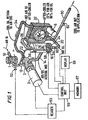
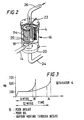
- the major components of a typical compressor are illustrated in Fig. 1. Air from an intake 10 passes through intake filter I and thence via line 12 to a rotary vane or screw compressor unit 2 driven by electric motor 3. A mixture of compressed air, water and oil is expelled from the compression unit and travels via line 14 to an oil separation unit 16 shown diagrammatically in Fig. 2.
- the stream of compressed air entering the unit 16 impinges onto a baffle 18 and the larger droplets coalesce and fall into a sump region 20.
- the air stream contains droplets of oil of size 0.3-1.5 ⁇ m, which are separated by means of a coalescing filter 4 of wrapped or molded glass micro-fibers so as to reduce contamination and recover the oil.
- Coalesced oil returns from the interior of the cartridge via a scavenging line 22 and line 12 to the compressor unit.
- the arrangement shown is for a vertical filter with flow in an out-to-in direction, but an in-to-out flow direction is commonplace, as also is a horizontal filter arrangement.
- Filtered air from the unit 16 passes via line 26 to the air side 28 of an after-cooler 5 and thence via output line 30 to a tank or distribution network or the like. Oil from the sump region 20 passes through filter 6 and the oil side 32 of the after-cooler 5. It then passes via line 34 into the compressor unit 2.
- Fig. 3 shows the pressure drop in milli-bars (Mb) against time for a typical coalescing filter 4.
- the pressure drop rises steeply during an initial period whilst the filter is wetting out with oil. It then rises only gradually until the bores become clogged with contaminant, at which time a region A is reached where the pressure drop rises sharply, operation of the compressor becomes inefficient and the expected output may not be achieved, for example after 12 months operation of the compressor.
- the time B at which a rapidly increasing pressure drop is experienced may be reduced, e.g. to about 6 months.
- a compressor is a device of relatively high value, is protected by the intake filter 1 and the oil filter 6 and has a coalescing filter which is intended to ensure that the air leaving the compressor conforms to defined quality levels.
- Users of the compressor may replace the filters supplied by the original equipment manufacturer with matching parts made by third parties whose quality is not under the control of the original equipment manufacturer and whose performance may be significantly poorer than that of the genuine spare part. There is therefore a risk that the replacement filter may fail before the manufacturer's recommended service interval for the filter has elapsed. There is also a risk that the user may not adhere to recommended service intervals. In consequence the compressor may become subject to excessive wear and may fail prematurely, or the quality of the output air may become deteriorated which may cause damage to downstream equipment.
- the original equipment manufacturer may be faced with a repair or warranty claim that is not justified, and may suffer undeserved damage to his reputation for supplying high quality equipment.
- the air from the compressor, even after passage through the coalescing filter may still contain undesirably high amounts of oil that may be in the form of very fine droplets or may be in the form of vapor.
- the extent of purification required will depend on the use to which the compressed air is to be put, which can be e.g. to blow dirt away from workpieces etc., for pneumatic controls and instrumentation and air tools, building air conditioning, paint spraying and pharmaceutical and electronic applications, To remove trace contaminants, it is common to provide one or more in-line filters.
- Fig. 4 shows an in-line coalescing filter having a filter head 40 provided with an air inlet 42 and an air outlet 44.
- a replaceable filter cartridge 46 is supported from the head 40 e.g.
- a tie rod 47 can be arranged for flow in an in-to-out direction as shown or in the reverse direction.
- Oil collects in a lower region of a filter bowl 48 and may be removed at intervals by means of a drain valve 50.
- a drain valve 50 Increasingly so-called "spun-on" filters are being used in which the filter and housing are supplied as a single disposable unit, which becomes threadedly attached to the filter head.
- an adsorbent cartridge filled with activated carbon replaces the coalescing filter 46.
- Oil coalescing filters and oil vapor removal cartridges are described, for example, in GB-A-1236396, 1557821, and 1609519, US-A-3841484 and EP-B-0081297. Again the user may not service the in-line filter with manufacturer's original parts and may not adhere to specified service intervals.
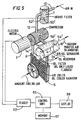
- FIG. 5 An oil-lubricated rotary vane vacuum pump is diagrammatically shown in Fig 5. Again air from the space being evacuated enters the pump unit 2 via an intake filter 1. Oil circulates between the pump unit 2, a cooler radiator 5 and through filter 6 into reservoir chamber 16". Air passes from the chamber 16" and coalescing filter 4 to exhaust. Again, deficient intake and oil filters 1,6, or undue delay in their replacement can lead to premature wear or failure of the pump, and a deficient coalescing filter 4 can lead to contamination of the surroundings with oil.
- the present invention aims to solve the above problem by providing replaceable filter elements in which there is concealed tamper-proof machine-readable identification.
- identification may be a single bit identification (i.e. the presence or absence of a record in memory or a device that will give a predetermined response to an interrogating signal) or it may be a multi-bit identification.
- a multi-bit identification may be used to provide a code, which may provide a family indication (e.g. manufacturer and model number) and a serial number, together with, if capacity permits, additional information such as date and place of manufacture and the like codes may be provided in a variety of forms.
- the stored information may be used to enable a check to be carried out that an approved filter is fitted.
- a change in serial number of the filter may be used to monitor compliance with approved times for filter exchange.
- a stored serial number can also be used to trace the manufacturing details of the filter in question from the records held by the manufacturer and assist in tracing the cause of the defect.
- non-contact identification technologies that may be applied to a filter to identify it with varying degrees of detail from mere type authentication to records of serial number etc. are set out below:
- the filter may also be marked by a marker that requites an electrical contact for recovery of the stored information.
- a ROM chip e.g. a so-called "silicon serial number" DS 2401 is available from Dallas Semiconductor. Such a chip is less than 5 mm square and only 1.5 mm deep and can readily be fitted to or encapsulated within a filter. It requires connection to ground (which may be to an end cap or side wall of the filter) and has a single pin for control, address, data and power, so that only a single lead going to a single contact area on the filter is required.
- the intake filter 1 carries a transponder 51 that can be interrogated by a first antenna 52 connected to a reader 53 controlled by a control unit 55 which may be a device controlled by a microprocessor or microcontroller,
- the coalescing filter also carries a transponder 54 that can be interrogated by a second antenna 56 in the unit 16 and also connected to the reader 53.
- the control unit also receives signals from devices that check the correct operation of the compressor, e.g. from an oil level sensor 58, an oil temperature sensor 60 and an exit air temperature sensor 62. On change of a filter, or on re-start of the compressor after an interruption, the control unit 55 causes the reader 53 to supply interrogating signals to the antennae 52,56.
- Returned data is checked to ascertain whether correct cartridges are in place. Assuming that both part identities and serial numbers are recorded in the memories of the transponders 51,54 stored instructions in the control unit 55 cause this information to be recorded in memory 57. If one or other filter does not provide a correct response or any response, then the control unit causes an indication of this fact to be stored in memory, It may also cause a warning to appear at display 59 and/or it may cause inhibit further operation of the compressor.
- the control unit 55 may be part of a service/diagnostic system for the compressor or vacuum pump, and if the presence of correct filters is not detected, it may simply log in memory 57 the fact that no correct identity signal has been recorded, this fact appearing with other performance data for the machine. A similar arrangement is shown for the vacuum pump of Fig. 5.
- An in-line filter can also have a transponder 70 fed with interrogating signals e.g. by means of an antenna 72.
- the filter medium usually takes the form of a tube 61 of pleated, wrapped or molded glass microfibre which is closed by metal or plastics end caps at each end.
- the identification device may be concealed within one or other of the end caps, and preferably within the end cap intended to fit within a filter head attached in-line or to a compressor, vacuum pump or other active device.
- one of the end caps may have a memory chip on or buried within it, the chip having an identity code recorded in memory and a connection to a metal component of the filter (which will normally be connected to earth) and a data lead.
- such a data lead may go to a contact nib 80 projecting from end cap 82 which when the filter is correctly positioned mates with a contact 84 in an adjoining portion 86 of the filter head.
- a contact ring 88 replaces the nib 80 so that a connection is made with the terminal 84 of the filter head irrespective of the angular position of the filter.
- Interrogation signals can then be transmitted directly from the filter head to a silicon serial number or other memory device fitted on or in the filter, and stored identity information can be recovered therefrom.
- a control unit can therefore check whether an approved filter is being used and by checking its internal clock whether correct filter exchange times are being obeyed.
- Means may be provided to measure the pressure drop across the coalescing and/or intake filters and may be arranged to generate a signal when the pressure drop has reached a predetermined value signifying that the filter element has reached the end of its useful life. If the time required is less than the manufacturer's service interval, the internal records of the compressor, vacuum pump or other active device may show that this is because an authentic replacement filter was not fitted.
- the invention is applicable to other forms of fluid filter e.g. oil filters for internal combustion engines.
- fluid filter e.g. oil filters for internal combustion engines.
- it can be used for air intake filters for internal combustion engines and compressed air systems used throughout the transport industry including aircraft, trains, ships, automobiles and goods vehicles.
- compressors used to provide a supply of compressed air for a ring-main system for a factory, hospital or other place where compressed air is used as a source of energy.
- It is also useful for underground interception filters for installations made by Conder and other manufacturers to condition outflow water from interceptor tanks of industrial installations (e.g. petroleum retail forecourts) or waste water prior to discharge into a coarse sewer or water-way.
- Fig 9 there is shown part of a filter having a plastics end cap 90 formed with an annular flanged and upturned region defining a resin well 92 which is formed with a recess 94 for receiving a memory chip.96 which could be a Dallas Silicon Serial Number or the like.
- a memory chip.96 which could be a Dallas Silicon Serial Number or the like.
- One side of the chip is grounded by connection (not shown) to metallic parts of the filter cartridge and its data pin is connected to a terminal 98 that appears through the exposed face of the end cap.
- the filter has inner and outer sleeves 100, 102 of expanded metal between which is sandwiched a mounded glass fibre coalescing filter 104.
- On the outer face of the sleeve 102 there is provided a drainage layer 106 of non-woven material.
- the above components are pushed into a layer of polyurethane adhesive in the well 92, and the adhesive is allowed to cure to complete the end of the filter, the chip 9 being held in a well-protected location. It will be appreciated that the above position is only one possibility and other locations for a chip or a transponder are possible e.g. between the coalescing filter 104 and the drainage layer 106.
Claims (3)
- Compresseur ou pompe à vide (2) comportant :un filtre d'entrée d'air (1) et/ou un filtre coalescent (4) pour conditionner le flux de gaz afin de maintenir le fonctionnement correct du compresseur ou de la pompe et qui requiert d'être remplacé périodiquement ;des moyens appliqués (51/54) audit filtre pour fournir une identification encastrée, lisible pour une machine de protection contre les manipulations correspondant audit filtre ;une tête de filtre ou une enceinte faisant partie dudit compresseur ou de ladite pompe à vide et comportant des moyens (52/56) pour détecter ladite identification ;des moyens pour mesurer la chute de pression à travers le filtre d'entrée d'air et ou le filtre coalescent et pour générer un signal lorsque la chute de pression atteint une valeur prédéterminée signifiant que le filtre a atteint la fin de sa durée de vie utile ; etdes moyens contrôle (55) pouvant agir pour interroger une nouvelle cartouche chaque fois que le filtre est changé pour récupérer l'identification, la stocker en mémoire (5) si un filtre à remplacement automatique a été adapté et fournir une indication si une durée de vie utile inférieure à la durée de service du fabricant est associée à la non utilisation d'un filtre de remplacement authentique.
- Compresseur ou pompe à vide selon la revendication 1, dans lequel (laquelle) l'identification comporte une identité partielle correspondant audit filtre.
- Compresseur ou pompe à vide selon la revendication 1, dans lequel (laquelle) l'identification inclut un numéro de série imputable aux détails de fabrication dudit filtre.
Applications Claiming Priority (4)
| Application Number | Priority Date | Filing Date | Title |
|---|---|---|---|
| GBGB9826671.1A GB9826671D0 (en) | 1998-12-03 | 1998-12-03 | Filters and active devices |
| GB9826671 | 1998-12-03 | ||
| PCT/GB1999/004017 WO2000032298A1 (fr) | 1998-12-03 | 1999-12-03 | Filtres pour fluides a identification cachee lisible par machine |
| CA002349275A CA2349275A1 (fr) | 1998-12-03 | 2001-05-31 | Filtres de fluide ayant une identification dissimulee lisible par les ordinateurs |
Publications (2)
| Publication Number | Publication Date |
|---|---|
| EP1135202A1 EP1135202A1 (fr) | 2001-09-26 |
| EP1135202B1 true EP1135202B1 (fr) | 2003-07-09 |
Family
ID=25682601
Family Applications (1)
| Application Number | Title | Priority Date | Filing Date |
|---|---|---|---|
| EP99959516A Expired - Lifetime EP1135202B1 (fr) | 1998-12-03 | 1999-12-03 | Compresseur ou pompe a vide employant des filtres pour fluides a identification cachee lisible par machine |
Country Status (6)
| Country | Link |
|---|---|
| EP (1) | EP1135202B1 (fr) |
| JP (1) | JP2002531237A (fr) |
| AT (1) | ATE244595T1 (fr) |
| CA (1) | CA2349275A1 (fr) |
| GB (1) | GB9826671D0 (fr) |
| WO (1) | WO2000032298A1 (fr) |
Families Citing this family (43)
| Publication number | Priority date | Publication date | Assignee | Title |
|---|---|---|---|---|
| US6436299B1 (en) | 1999-06-21 | 2002-08-20 | Amway Corporation | Water treatment system with an inductively coupled ballast |
| US6673250B2 (en) | 1999-06-21 | 2004-01-06 | Access Business Group International Llc | Radio frequency identification system for a fluid treatment system |
| CA2541462C (fr) * | 1999-06-21 | 2014-09-09 | Access Business Group International Llc | Systeme de traitement par un fluide |
| DE19955685A1 (de) * | 1999-11-19 | 2001-05-23 | Ksb Ag | Identifikationselement |
| DE10000435A1 (de) | 2000-01-10 | 2001-07-12 | Mann & Hummel Filter | Verfahren und Vorrichtung zur Überwachung wartungsintensiver Austauschteile an einem Aggregat |
| US20020082746A1 (en) * | 2000-12-27 | 2002-06-27 | Honeywell International Inc. | Replaceable media with programmable device |
| DE20104481U1 (de) * | 2001-03-15 | 2001-06-13 | Ultrafilter Internat Ag | Druckluftfilter |
| JP2002366688A (ja) * | 2001-06-08 | 2002-12-20 | Mitsubishi Heavy Ind Ltd | フィルタの管理方法及び同方法で管理されるフィルタ |
| DE10151271B4 (de) | 2001-10-17 | 2010-01-07 | Sartorius Stedim Biotech Gmbh | Verfahren zur Durchführung von Integritätstests von Filterlementen |
| DE10165044B4 (de) * | 2001-10-17 | 2013-01-24 | Sartorius Stedim Biotech Gmbh | Vorrichtung zur Durchführung von Integritätstests von Filterelementen |
| DE10165007B4 (de) * | 2001-11-27 | 2009-08-27 | Sartorius Stedim Biotech Gmbh | Filtrationssystem zur Durchführung und Überwachung eines Filtrationsprozesses von Fluiden |
| DE10160429B4 (de) * | 2001-12-08 | 2008-05-08 | Sartorius Stedim Biotech Gmbh | Filter mit einem elektronischen Speicherelement |
| US7481917B2 (en) * | 2004-03-05 | 2009-01-27 | Hydranautics | Filtration devices with embedded radio frequency identification (RFID) tags |
| ES2452480T3 (es) | 2005-09-07 | 2014-04-01 | Hydranautics | Dispositivos de filtración por osmosis inversa con caudalímetros y medidores de conductividad alimentados por etiquetas de RFID |
| DE102005050635B4 (de) * | 2005-10-20 | 2016-06-09 | Knorr-Bremse Systeme für Nutzfahrzeuge GmbH | System und Verfahren zum Erkennen von Eigenschaften einer Luftfilterpatrone |
| EP2001578A4 (fr) | 2006-03-13 | 2010-06-02 | Hydranautics | Dispositif de mesure du debit et de la conductivite d'un permeat dans des elements a membrane d'osmose inverse individuels |
| FR2898964A1 (fr) * | 2006-03-27 | 2007-09-28 | Philippe Bianic | Systeme de suivi des filtres a air par radio frequence |
| WO2008007625A1 (fr) * | 2006-07-11 | 2008-01-17 | Komatsu Ltd. | Système de contrôle d'élément d'une machine |
| US9334820B2 (en) | 2006-07-11 | 2016-05-10 | Komatsu Ltd. | Working machine component monitoring system |
| US7811365B2 (en) * | 2006-10-16 | 2010-10-12 | Millipore Corporation | Wireless receptor for communications within housings |
| US7699989B2 (en) | 2006-10-17 | 2010-04-20 | Millipore Corporation | Powered cartridges and other devices within housings |
| JP5194736B2 (ja) * | 2007-11-20 | 2013-05-08 | セイコーエプソン株式会社 | フィルタ |
| NL2001383C2 (nl) * | 2008-03-17 | 2009-09-21 | Trans Elektro B V | Luchtfilter, inrichting voor het filteren van lucht, cabine voorzien van een dergelijke filterinrichting en werkwijze voor het filteren van lucht. |
| US8501119B2 (en) | 2008-03-26 | 2013-08-06 | Emd Millipore Corporation | Contactless power solution for low power sensors in bioprocess environments |
| DE102008022630B4 (de) | 2008-05-08 | 2015-12-31 | Bayerische Motoren Werke Aktiengesellschaft | Fahrzeugklimaanlage mit einem Filterelement mit Feuchtesensor und Verfahren zum Betreiben einer Fahrzeugklimaanlage |
| DE102008049862B4 (de) * | 2008-10-01 | 2022-09-01 | Carl Freudenberg Kg | Filterelement mit einem Mittel zur Lokalisierung und Identifizierung |
| DE102009011824A1 (de) * | 2009-03-05 | 2010-09-09 | Knorr-Bremse Systeme für Nutzfahrzeuge GmbH | System aus einer einem Nutzfahrzeug zugeordneten Luftaufbereitungsanlage und einer Luftfilterpatrone |
| WO2011000115A1 (fr) * | 2009-07-03 | 2011-01-06 | Smart Wave Integrated Products , Inc. | Système et procédé de communication entre un appareil de filtration de fluide et un filtre |
| US8727744B2 (en) * | 2010-02-26 | 2014-05-20 | Entegris, Inc. | Method and system for optimizing operation of a pump |
| US8684705B2 (en) * | 2010-02-26 | 2014-04-01 | Entegris, Inc. | Method and system for controlling operation of a pump based on filter information in a filter information tag |
| DE102010038064B4 (de) * | 2010-10-08 | 2013-02-21 | Haldex Brake Products Gmbh | Lufttrocknungskartusche |
| TWI563351B (en) | 2010-10-20 | 2016-12-21 | Entegris Inc | Method and system for pump priming |
| JP5607132B2 (ja) * | 2012-11-19 | 2014-10-15 | 株式会社小松製作所 | Icタグ付きフィルターおよびフィルター用のicタグ |
| ES2623539T3 (es) | 2012-12-19 | 2017-07-11 | Delaval Holding Ab | Disposición de ordeño, conjunto de partes desechables intercambiables y método para una disposición de ordeño |
| JP2013136058A (ja) * | 2013-02-26 | 2013-07-11 | Nippon Torimu:Kk | 電解整水装置 |
| DE102014007719A1 (de) * | 2014-05-28 | 2015-12-03 | Mann + Hummel Gmbh | Filtergehäuse und Filterelement für ein Filtersystem |
| US9707502B1 (en) * | 2016-09-26 | 2017-07-18 | 3M Innovative Properties Company | Conductive loop detection member |
| JP6736609B2 (ja) | 2017-06-30 | 2020-08-05 | ザ エスワイ−クロン カンパニー エルエルシー | 空気質監視および制御システム |
| EP3787724A4 (fr) * | 2018-05-29 | 2022-01-12 | AG Industries LLC | Procédé, appareil, et système d'oxygène à filtre |
| DE202019005615U1 (de) * | 2018-09-05 | 2021-03-12 | Atlas Copco Airpower, N.V. | Filter |
| BE1026882B1 (nl) * | 2018-12-18 | 2020-07-22 | Atlas Copco Airpower Nv | Filter |
| CN110963628B (zh) * | 2019-11-07 | 2022-11-01 | 艾斯迪(天津)汽车零部件有限公司 | 一种加工中心切削液净化装置 |
| JP7305518B2 (ja) * | 2019-11-08 | 2023-07-10 | ヤマシンフィルタ株式会社 | フィルタ装置 |
Family Cites Families (6)
| Publication number | Priority date | Publication date | Assignee | Title |
|---|---|---|---|---|
| US3841484A (en) * | 1969-12-06 | 1974-10-15 | Hunter D Eng Ltd | Fluid filter with color indicator |
| NL9300554A (nl) * | 1993-03-29 | 1994-10-17 | Doctro A V V | Samenstel van filterinrichting en een vervangbaar filter; alsmede filterinrichting en filter voor toepassing daarin. |
| FR2729088B1 (fr) * | 1995-01-05 | 1997-03-28 | Genevet Sa | Manches filtrantes pour filtres a manches |
| CA2180488A1 (fr) * | 1995-07-11 | 1997-01-12 | Roger Edward Page | Filtres |
| DE19601651A1 (de) * | 1996-01-18 | 1997-07-24 | Sander Karl Heinz Gmbh & Co Kg | Kanalisationsanlage |
| US6186140B1 (en) * | 1997-03-14 | 2001-02-13 | 3M Innovative Properties Company | Respiratory filter element having a storage device for keeping track of filter usage and a system for use therewith |
-
1998
- 1998-12-03 GB GBGB9826671.1A patent/GB9826671D0/en not_active Ceased
-
1999
- 1999-12-03 EP EP99959516A patent/EP1135202B1/fr not_active Expired - Lifetime
- 1999-12-03 WO PCT/GB1999/004017 patent/WO2000032298A1/fr active IP Right Grant
- 1999-12-03 JP JP2000584981A patent/JP2002531237A/ja active Pending
- 1999-12-03 AT AT99959516T patent/ATE244595T1/de not_active IP Right Cessation
-
2001
- 2001-05-31 CA CA002349275A patent/CA2349275A1/fr not_active Abandoned
Also Published As
| Publication number | Publication date |
|---|---|
| EP1135202A1 (fr) | 2001-09-26 |
| CA2349275A1 (fr) | 2002-11-30 |
| GB9826671D0 (en) | 1999-01-27 |
| WO2000032298A1 (fr) | 2000-06-08 |
| JP2002531237A (ja) | 2002-09-24 |
| ATE244595T1 (de) | 2003-07-15 |
Similar Documents
| Publication | Publication Date | Title |
|---|---|---|
| EP1135202B1 (fr) | Compresseur ou pompe a vide employant des filtres pour fluides a identification cachee lisible par machine | |
| US6558444B1 (en) | Fluid filters having a concealed machine-readable identification | |
| US6711524B2 (en) | Method and apparatus for monitoring service-intensive replaceable parts in an assembly | |
| US11654390B2 (en) | Filter systems, elements and methods with short-range wireless tracking features | |
| EP1763393A1 (fr) | Ensemble de filtre possédant une antenne | |
| US20080060983A1 (en) | Filter Element and Associated Data Transmission Device | |
| US20220084387A1 (en) | Multi-zone filtration monitoring systems and methods | |
| JPH09500816A (ja) | ろ過装置及び変換可能なフィルタの組立体、及びろ過装置並びに該ろ過装置内で使用されるフィルタ | |
| CN110876874B (zh) | 过滤器 | |
| US11779870B2 (en) | Smart filter elements and systems | |
| WO2019046274A1 (fr) | Verrouillage pour reconnaissance de filtre authentique | |
| CN113056600B (zh) | 具有多层数据交换能力的过滤系统 | |
| CN111714939B (zh) | 装置、组件和用于检测过滤器元件的方法 | |
| JPH0614484U (ja) | スクリュー圧縮機における油供給装置 |
Legal Events
| Date | Code | Title | Description |
|---|---|---|---|
| PUAI | Public reference made under article 153(3) epc to a published international application that has entered the european phase |
Free format text: ORIGINAL CODE: 0009012 |
|
| 17P | Request for examination filed |
Effective date: 20010605 |
|
| AK | Designated contracting states |
Kind code of ref document: A1 Designated state(s): AT BE CH CY DE DK ES FI FR GB GR IE IT LI LU MC NL PT SE |
|
| 17Q | First examination report despatched |
Effective date: 20020214 |
|
| GRAH | Despatch of communication of intention to grant a patent |
Free format text: ORIGINAL CODE: EPIDOS IGRA |
|
| RTI1 | Title (correction) |
Free format text: COMPRESSOR OR VACUUM PUMP EMPLOYING FLUID FILTERS HAVING A CONCEALED MACHINE-READABLE IDENTIFICATION |
|
| GRAH | Despatch of communication of intention to grant a patent |
Free format text: ORIGINAL CODE: EPIDOS IGRA |
|
| GRAA | (expected) grant |
Free format text: ORIGINAL CODE: 0009210 |
|
| AK | Designated contracting states |
Designated state(s): AT BE CH CY DE DK ES FI FR GB GR IE IT LI LU MC NL PT SE |
|
| PG25 | Lapsed in a contracting state [announced via postgrant information from national office to epo] |
Ref country code: AT Free format text: LAPSE BECAUSE OF FAILURE TO SUBMIT A TRANSLATION OF THE DESCRIPTION OR TO PAY THE FEE WITHIN THE PRESCRIBED TIME-LIMIT Effective date: 20030709 |
|
| REG | Reference to a national code |
Ref country code: GB Ref legal event code: FG4D |
|
| REG | Reference to a national code |
Ref country code: CH Ref legal event code: EP |
|
| REF | Corresponds to: |
Ref document number: 69909507 Country of ref document: DE Date of ref document: 20030814 Kind code of ref document: P |
|
| REG | Reference to a national code |
Ref country code: IE Ref legal event code: FG4D |
|
| PG25 | Lapsed in a contracting state [announced via postgrant information from national office to epo] |
Ref country code: GR Free format text: LAPSE BECAUSE OF FAILURE TO SUBMIT A TRANSLATION OF THE DESCRIPTION OR TO PAY THE FEE WITHIN THE PRESCRIBED TIME-LIMIT Effective date: 20031009 |
|
| REG | Reference to a national code |
Ref country code: SE Ref legal event code: TRGR |
|
| REG | Reference to a national code |
Ref country code: CH Ref legal event code: NV Representative=s name: BRAUN & PARTNER PATENT-, MARKEN-, RECHTSANWAELTE |
|
| NLR4 | Nl: receipt of corrected translation in the netherlands language at the initiative of the proprietor of the patent | ||
| PG25 | Lapsed in a contracting state [announced via postgrant information from national office to epo] |
Ref country code: LU Free format text: LAPSE BECAUSE OF NON-PAYMENT OF DUE FEES Effective date: 20031203 Ref country code: IE Free format text: LAPSE BECAUSE OF NON-PAYMENT OF DUE FEES Effective date: 20031203 Ref country code: CY Free format text: LAPSE BECAUSE OF FAILURE TO SUBMIT A TRANSLATION OF THE DESCRIPTION OR TO PAY THE FEE WITHIN THE PRESCRIBED TIME-LIMIT Effective date: 20031203 |
|
| PG25 | Lapsed in a contracting state [announced via postgrant information from national office to epo] |
Ref country code: PT Free format text: LAPSE BECAUSE OF FAILURE TO SUBMIT A TRANSLATION OF THE DESCRIPTION OR TO PAY THE FEE WITHIN THE PRESCRIBED TIME-LIMIT Effective date: 20031209 |
|
| PG25 | Lapsed in a contracting state [announced via postgrant information from national office to epo] |
Ref country code: MC Free format text: LAPSE BECAUSE OF NON-PAYMENT OF DUE FEES Effective date: 20031231 |
|
| REG | Reference to a national code |
Ref country code: ES Ref legal event code: FG2A Ref document number: 2203218 Country of ref document: ES Kind code of ref document: T3 |
|
| PLBE | No opposition filed within time limit |
Free format text: ORIGINAL CODE: 0009261 |
|
| STAA | Information on the status of an ep patent application or granted ep patent |
Free format text: STATUS: NO OPPOSITION FILED WITHIN TIME LIMIT |
|
| ET | Fr: translation filed | ||
| 26N | No opposition filed |
Effective date: 20040414 |
|
| REG | Reference to a national code |
Ref country code: IE Ref legal event code: MM4A |
|
| PGFP | Annual fee paid to national office [announced via postgrant information from national office to epo] |
Ref country code: NL Payment date: 20071214 Year of fee payment: 9 Ref country code: ES Payment date: 20071207 Year of fee payment: 9 Ref country code: DK Payment date: 20071218 Year of fee payment: 9 |
|
| PGFP | Annual fee paid to national office [announced via postgrant information from national office to epo] |
Ref country code: CH Payment date: 20071213 Year of fee payment: 9 Ref country code: FI Payment date: 20071210 Year of fee payment: 9 Ref country code: IT Payment date: 20071206 Year of fee payment: 9 |
|
| PGFP | Annual fee paid to national office [announced via postgrant information from national office to epo] |
Ref country code: BE Payment date: 20071231 Year of fee payment: 9 Ref country code: SE Payment date: 20071212 Year of fee payment: 9 |
|
| PGFP | Annual fee paid to national office [announced via postgrant information from national office to epo] |
Ref country code: GB Payment date: 20071206 Year of fee payment: 9 Ref country code: FR Payment date: 20071207 Year of fee payment: 9 |
|
| PGFP | Annual fee paid to national office [announced via postgrant information from national office to epo] |
Ref country code: DE Payment date: 20071228 Year of fee payment: 9 |
|
| BERE | Be: lapsed |
Owner name: *PSI GLOBAL LTD Effective date: 20081231 |
|
| PG25 | Lapsed in a contracting state [announced via postgrant information from national office to epo] |
Ref country code: FI Free format text: LAPSE BECAUSE OF NON-PAYMENT OF DUE FEES Effective date: 20081203 |
|
| REG | Reference to a national code |
Ref country code: CH Ref legal event code: PL |
|
| REG | Reference to a national code |
Ref country code: DK Ref legal event code: EBP |
|
| EUG | Se: european patent has lapsed | ||
| GBPC | Gb: european patent ceased through non-payment of renewal fee |
Effective date: 20081203 |
|
| NLV4 | Nl: lapsed or anulled due to non-payment of the annual fee |
Effective date: 20090701 |
|
| PG25 | Lapsed in a contracting state [announced via postgrant information from national office to epo] |
Ref country code: BE Free format text: LAPSE BECAUSE OF NON-PAYMENT OF DUE FEES Effective date: 20081231 |
|
| REG | Reference to a national code |
Ref country code: FR Ref legal event code: ST Effective date: 20090831 |
|
| PG25 | Lapsed in a contracting state [announced via postgrant information from national office to epo] |
Ref country code: LI Free format text: LAPSE BECAUSE OF NON-PAYMENT OF DUE FEES Effective date: 20081231 Ref country code: DE Free format text: LAPSE BECAUSE OF NON-PAYMENT OF DUE FEES Effective date: 20090701 Ref country code: CH Free format text: LAPSE BECAUSE OF NON-PAYMENT OF DUE FEES Effective date: 20081231 |
|
| PG25 | Lapsed in a contracting state [announced via postgrant information from national office to epo] |
Ref country code: NL Free format text: LAPSE BECAUSE OF NON-PAYMENT OF DUE FEES Effective date: 20090701 Ref country code: GB Free format text: LAPSE BECAUSE OF NON-PAYMENT OF DUE FEES Effective date: 20081203 |
|
| PG25 | Lapsed in a contracting state [announced via postgrant information from national office to epo] |
Ref country code: DK Free format text: LAPSE BECAUSE OF NON-PAYMENT OF DUE FEES Effective date: 20090105 |
|
| REG | Reference to a national code |
Ref country code: ES Ref legal event code: FD2A Effective date: 20081204 |
|
| PG25 | Lapsed in a contracting state [announced via postgrant information from national office to epo] |
Ref country code: FR Free format text: LAPSE BECAUSE OF NON-PAYMENT OF DUE FEES Effective date: 20081231 Ref country code: ES Free format text: LAPSE BECAUSE OF NON-PAYMENT OF DUE FEES Effective date: 20081204 |
|
| PG25 | Lapsed in a contracting state [announced via postgrant information from national office to epo] |
Ref country code: SE Free format text: LAPSE BECAUSE OF NON-PAYMENT OF DUE FEES Effective date: 20081204 |
|
| PG25 | Lapsed in a contracting state [announced via postgrant information from national office to epo] |
Ref country code: IT Free format text: LAPSE BECAUSE OF NON-PAYMENT OF DUE FEES Effective date: 20081203 |