EP1135202B1 - Compressor or vacuum pump employing fluid filters having a concealed machine-readable identification - Google Patents
Compressor or vacuum pump employing fluid filters having a concealed machine-readable identification Download PDFInfo
- Publication number
- EP1135202B1 EP1135202B1 EP99959516A EP99959516A EP1135202B1 EP 1135202 B1 EP1135202 B1 EP 1135202B1 EP 99959516 A EP99959516 A EP 99959516A EP 99959516 A EP99959516 A EP 99959516A EP 1135202 B1 EP1135202 B1 EP 1135202B1
- Authority
- EP
- European Patent Office
- Prior art keywords
- filter
- compressor
- vacuum pump
- identification
- coalescing
- Prior art date
- Legal status (The legal status is an assumption and is not a legal conclusion. Google has not performed a legal analysis and makes no representation as to the accuracy of the status listed.)
- Expired - Lifetime
Links
Images


Classifications
-
- B—PERFORMING OPERATIONS; TRANSPORTING
- B01—PHYSICAL OR CHEMICAL PROCESSES OR APPARATUS IN GENERAL
- B01D—SEPARATION
- B01D46/00—Filters or filtering processes specially modified for separating dispersed particles from gases or vapours
- B01D46/0084—Filters or filtering processes specially modified for separating dispersed particles from gases or vapours provided with safety means
- B01D46/009—Identification of filter type or position thereof, e.g. by transponders or bar codes
-
- B—PERFORMING OPERATIONS; TRANSPORTING
- B01—PHYSICAL OR CHEMICAL PROCESSES OR APPARATUS IN GENERAL
- B01D—SEPARATION
- B01D46/00—Filters or filtering processes specially modified for separating dispersed particles from gases or vapours
- B01D46/0027—Filters or filtering processes specially modified for separating dispersed particles from gases or vapours with additional separating or treating functions
- B01D46/003—Filters or filtering processes specially modified for separating dispersed particles from gases or vapours with additional separating or treating functions including coalescing means for the separation of liquid
-
- B—PERFORMING OPERATIONS; TRANSPORTING
- B01—PHYSICAL OR CHEMICAL PROCESSES OR APPARATUS IN GENERAL
- B01D—SEPARATION
- B01D46/00—Filters or filtering processes specially modified for separating dispersed particles from gases or vapours
- B01D46/0084—Filters or filtering processes specially modified for separating dispersed particles from gases or vapours provided with safety means
- B01D46/0086—Filter condition indicators
-
- B—PERFORMING OPERATIONS; TRANSPORTING
- B01—PHYSICAL OR CHEMICAL PROCESSES OR APPARATUS IN GENERAL
- B01D—SEPARATION
- B01D46/00—Filters or filtering processes specially modified for separating dispersed particles from gases or vapours
- B01D46/42—Auxiliary equipment or operation thereof
- B01D46/429—Means for wireless communication
-
- B—PERFORMING OPERATIONS; TRANSPORTING
- B01—PHYSICAL OR CHEMICAL PROCESSES OR APPARATUS IN GENERAL
- B01D—SEPARATION
- B01D2201/00—Details relating to filtering apparatus
- B01D2201/40—Special measures for connecting different parts of the filter
- B01D2201/4046—Means for avoiding false mounting of different parts
-
- B—PERFORMING OPERATIONS; TRANSPORTING
- B01—PHYSICAL OR CHEMICAL PROCESSES OR APPARATUS IN GENERAL
- B01D—SEPARATION
- B01D2201/00—Details relating to filtering apparatus
- B01D2201/56—Wireless systems for monitoring the filter
Landscapes
- Chemical & Material Sciences (AREA)
- Chemical Kinetics & Catalysis (AREA)
- Engineering & Computer Science (AREA)
- Computer Networks & Wireless Communication (AREA)
- Filtering Of Dispersed Particles In Gases (AREA)
- Solid-Sorbent Or Filter-Aiding Compositions (AREA)
- Compressors, Vaccum Pumps And Other Relevant Systems (AREA)
- Compressor (AREA)
Abstract
Description
Claims (3)
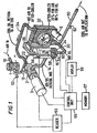
- A compressor or vacuum pump (2) having;
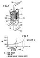
an air intake filter (1) and/or a coalescing filter (4) for conditioning the flow of gas to maintain the correct functioning of the compressor or pump and which requires to be replaced periodically;
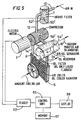
means applied (51/54) to said filter for providing concealed tamper-proof machine-readable identification for said filter;
a filter head or housing forming part of said compressor or vacuum pump and having means (52/56) for detecting said identification;
means for measuring the pressure drop across the air intake filter and or the coalescing filter and for generating a signal when the pressure drop has reached a predetermined value signifying that the filter has reached the end of its useful life; and
control means (55) operable to interrogate a new cartridge whenever the filter is changed to recover the identification, store in memory (5) whether an automatic replacement filter has been fitted and provide an indication whether a useful life less than the manufacturer's service interval is associated with non-use of an authentic replacement filter. - The compressor or vacuum pump of claim 1, wherein the identification comprises a part identity for said filter.
- The compressor or vacuum pump of claim 1, wherein the identification includes a serial number traceable to the manufacturing details of said filter.
Applications Claiming Priority (4)
| Application Number | Priority Date | Filing Date | Title |
|---|---|---|---|
| GBGB9826671.1A GB9826671D0 (en) | 1998-12-03 | 1998-12-03 | Filters and active devices |
| GB9826671 | 1998-12-03 | ||
| PCT/GB1999/004017 WO2000032298A1 (en) | 1998-12-03 | 1999-12-03 | Fluid filters having a concealed machine-readable identification |
| CA002349275A CA2349275A1 (en) | 1998-12-03 | 2001-05-31 | Fluid filters having a concealed machine-readable identification |
Publications (2)
| Publication Number | Publication Date |
|---|---|
| EP1135202A1 EP1135202A1 (en) | 2001-09-26 |
| EP1135202B1 true EP1135202B1 (en) | 2003-07-09 |
Family
ID=25682601
Family Applications (1)
| Application Number | Title | Priority Date | Filing Date |
|---|---|---|---|
| EP99959516A Expired - Lifetime EP1135202B1 (en) | 1998-12-03 | 1999-12-03 | Compressor or vacuum pump employing fluid filters having a concealed machine-readable identification |
Country Status (6)
| Country | Link |
|---|---|
| EP (1) | EP1135202B1 (en) |
| JP (1) | JP2002531237A (en) |
| AT (1) | ATE244595T1 (en) |
| CA (1) | CA2349275A1 (en) |
| GB (1) | GB9826671D0 (en) |
| WO (1) | WO2000032298A1 (en) |
Families Citing this family (43)
| Publication number | Priority date | Publication date | Assignee | Title |
|---|---|---|---|---|
| US6436299B1 (en) | 1999-06-21 | 2002-08-20 | Amway Corporation | Water treatment system with an inductively coupled ballast |
| US6673250B2 (en) * | 1999-06-21 | 2004-01-06 | Access Business Group International Llc | Radio frequency identification system for a fluid treatment system |
| WO2000078678A2 (en) * | 1999-06-21 | 2000-12-28 | Amway Corporation | Fluid treatment system with electromagnetic radiation |
| DE19955685A1 (en) * | 1999-11-19 | 2001-05-23 | Ksb Ag | Component has electronic identification element with data for component in electronic form in memory; access to data and/or for data modification is gained with read and/or write device |
| DE10000435A1 (en) | 2000-01-10 | 2001-07-12 | Mann & Hummel Filter | Monitoring maintenance-intensive replacement parts involves storing part specifying data, reading into evaluation unit at predefined times or at predetermined intervals using suitable reader |
| US20020082746A1 (en) * | 2000-12-27 | 2002-06-27 | Honeywell International Inc. | Replaceable media with programmable device |
| DE20104481U1 (en) * | 2001-03-15 | 2001-06-13 | Ultrafilter Internat Ag | Compressed air filter |
| JP2002366688A (en) * | 2001-06-08 | 2002-12-20 | Mitsubishi Heavy Ind Ltd | Managing method for filter and filter to be managed by the same |
| DE10151271B4 (en) * | 2001-10-17 | 2010-01-07 | Sartorius Stedim Biotech Gmbh | Method for performing integrity tests of filter elements |
| DE10165044B4 (en) * | 2001-10-17 | 2013-01-24 | Sartorius Stedim Biotech Gmbh | Filter pneumatic test assembly has control unit linked by radio transponder to communications device near the filter element under test |
| DE10157798B4 (en) * | 2001-11-27 | 2008-01-03 | Sartorius Biotech Gmbh | Method for carrying out a filtration process of fluids |
| DE10160429B4 (en) * | 2001-12-08 | 2008-05-08 | Sartorius Stedim Biotech Gmbh | Filter with an electronic memory element |
| US7481917B2 (en) | 2004-03-05 | 2009-01-27 | Hydranautics | Filtration devices with embedded radio frequency identification (RFID) tags |
| JP5225088B2 (en) | 2005-09-07 | 2013-07-03 | ハイドラノーティックス | Reverse osmosis filtration device with flow meter and conductivity meter powered by RFID tag |
| DE102005050635B4 (en) * | 2005-10-20 | 2016-06-09 | Knorr-Bremse Systeme für Nutzfahrzeuge GmbH | System and method for detecting properties of an air filter cartridge |
| CN101443098A (en) | 2006-03-13 | 2009-05-27 | 海德拉罗迪克斯公司 | Device for measuring permeate flow and permeate conductivity of individual reverse osmosis membrane elements |
| FR2898964A1 (en) * | 2006-03-27 | 2007-09-28 | Philippe Bianic | Interchangeable gas/air filter`s usage time and parameter monitoring device for e.g. hood, has radio frequency transmitter/receivers integrated to clean chamber, and electronic card registering dates for changing/replacing filter |
| US9334820B2 (en) | 2006-07-11 | 2016-05-10 | Komatsu Ltd. | Working machine component monitoring system |
| CN101512614B (en) * | 2006-07-11 | 2012-08-29 | 株式会社小松制作所 | System for monitoring component of operating machine |
| US7811365B2 (en) * | 2006-10-16 | 2010-10-12 | Millipore Corporation | Wireless receptor for communications within housings |
| US7699989B2 (en) * | 2006-10-17 | 2010-04-20 | Millipore Corporation | Powered cartridges and other devices within housings |
| JP5194736B2 (en) * | 2007-11-20 | 2013-05-08 | セイコーエプソン株式会社 | filter |
| NL2001383C2 (en) * | 2008-03-17 | 2009-09-21 | Trans Elektro B V | Air filter for filtering polluted air in cabin within e.g. vehicle, has filter material to filter air, and container for holding filter material, where electronic pressure readout identifiers are provided for identifying air filter |
| US8501119B2 (en) * | 2008-03-26 | 2013-08-06 | Emd Millipore Corporation | Contactless power solution for low power sensors in bioprocess environments |
| DE102008022630B4 (en) | 2008-05-08 | 2015-12-31 | Bayerische Motoren Werke Aktiengesellschaft | Vehicle air conditioning system with a filter element with humidity sensor and method for operating a vehicle air conditioning system |
| DE102008049862B4 (en) * | 2008-10-01 | 2022-09-01 | Carl Freudenberg Kg | Filter element with means for locating and identifying |
| DE102009011824A1 (en) * | 2009-03-05 | 2010-09-09 | Knorr-Bremse Systeme für Nutzfahrzeuge GmbH | System of a commercial vehicle associated with an air treatment plant and an air filter cartridge |
| WO2011000115A1 (en) * | 2009-07-03 | 2011-01-06 | Smart Wave Integrated Products , Inc. | System and method for communication between a fluid filtration apparatus and filter |
| US8684705B2 (en) | 2010-02-26 | 2014-04-01 | Entegris, Inc. | Method and system for controlling operation of a pump based on filter information in a filter information tag |
| US8727744B2 (en) * | 2010-02-26 | 2014-05-20 | Entegris, Inc. | Method and system for optimizing operation of a pump |
| DE102010038064B4 (en) * | 2010-10-08 | 2013-02-21 | Haldex Brake Products Gmbh | Air drying cartridge |
| TWI563351B (en) | 2010-10-20 | 2016-12-21 | Entegris Inc | Method and system for pump priming |
| JP5607132B2 (en) * | 2012-11-19 | 2014-10-15 | 株式会社小松製作所 | Filter with IC tag and IC tag for filter |
| EP2934098B1 (en) | 2012-12-19 | 2017-02-01 | DeLaval Holding AB | Milking arrangement, set of exchangeable expendable parts and method for a milking arrangement |
| JP2013136058A (en) * | 2013-02-26 | 2013-07-11 | Nippon Torimu:Kk | Electrolytic water conditioner |
| DE102014007719A1 (en) * | 2014-05-28 | 2015-12-03 | Mann + Hummel Gmbh | Filter housing and filter element for a filter system |
| US9707502B1 (en) * | 2016-09-26 | 2017-07-18 | 3M Innovative Properties Company | Conductive loop detection member |
| BR102018013533B1 (en) * | 2017-06-30 | 2023-12-26 | The Sy-Klone Company, Llc | AIR QUALITY SYSTEM AND AIR QUALITY SYSTEM MONITORING METHOD |
| EP3787724A4 (en) * | 2018-05-29 | 2022-01-12 | AG Industries LLC | Filter oxygen method, apparatus and system |
| BR212021003960U2 (en) * | 2018-09-05 | 2021-09-21 | Atlas Copco Airpower, Naamloze Vennootschap | FILTER |
| BE1026882B1 (en) * | 2018-12-18 | 2020-07-22 | Atlas Copco Airpower Nv | Filter |
| CN110963628B (en) * | 2019-11-07 | 2022-11-01 | 艾斯迪(天津)汽车零部件有限公司 | Machining center cutting fluid purifier |
| JP7305518B2 (en) * | 2019-11-08 | 2023-07-10 | ヤマシンフィルタ株式会社 | filter device |
Family Cites Families (6)
| Publication number | Priority date | Publication date | Assignee | Title |
|---|---|---|---|---|
| US3841484A (en) * | 1969-12-06 | 1974-10-15 | Hunter D Eng Ltd | Fluid filter with color indicator |
| NL9300554A (en) * | 1993-03-29 | 1994-10-17 | Doctro A V V | Assembly of filter device and a replaceable filter; as well as filter device and filter for use therein. |
| FR2729088B1 (en) * | 1995-01-05 | 1997-03-28 | Genevet Sa | FILTER HANDLES FOR SLEEVE FILTERS |
| CA2180488A1 (en) * | 1995-07-11 | 1997-01-12 | Roger Edward Page | Filters |
| DE19601651A1 (en) * | 1996-01-18 | 1997-07-24 | Sander Karl Heinz Gmbh & Co Kg | Sewerage system |
| US6186140B1 (en) * | 1997-03-14 | 2001-02-13 | 3M Innovative Properties Company | Respiratory filter element having a storage device for keeping track of filter usage and a system for use therewith |
-
1998
- 1998-12-03 GB GBGB9826671.1A patent/GB9826671D0/en not_active Ceased
-
1999
- 1999-12-03 AT AT99959516T patent/ATE244595T1/en not_active IP Right Cessation
- 1999-12-03 JP JP2000584981A patent/JP2002531237A/en active Pending
- 1999-12-03 EP EP99959516A patent/EP1135202B1/en not_active Expired - Lifetime
- 1999-12-03 WO PCT/GB1999/004017 patent/WO2000032298A1/en active IP Right Grant
-
2001
- 2001-05-31 CA CA002349275A patent/CA2349275A1/en not_active Abandoned
Also Published As
| Publication number | Publication date |
|---|---|
| JP2002531237A (en) | 2002-09-24 |
| EP1135202A1 (en) | 2001-09-26 |
| WO2000032298A1 (en) | 2000-06-08 |
| CA2349275A1 (en) | 2002-11-30 |
| ATE244595T1 (en) | 2003-07-15 |
| GB9826671D0 (en) | 1999-01-27 |
Similar Documents
| Publication | Publication Date | Title |
|---|---|---|
| EP1135202B1 (en) | Compressor or vacuum pump employing fluid filters having a concealed machine-readable identification | |
| US6558444B1 (en) | Fluid filters having a concealed machine-readable identification | |
| US6711524B2 (en) | Method and apparatus for monitoring service-intensive replaceable parts in an assembly | |
| JP7427749B2 (en) | Filter system, filter element and method with short range wireless feature tracking | |
| WO2005113112A1 (en) | Filter assembly having antenna | |
| US20080060983A1 (en) | Filter Element and Associated Data Transmission Device | |
| US20220084387A1 (en) | Multi-zone filtration monitoring systems and methods | |
| JPH09500816A (en) | Filtration device and convertible filter assembly, and filtration device and filter used in the filtration device | |
| CN210543965U (en) | Filter | |
| US11779870B2 (en) | Smart filter elements and systems | |
| WO2019046274A1 (en) | Interlock for genuine filter recognition | |
| CN207761855U (en) | Filter assembly and engine | |
| CN113056600B (en) | Filtration system with multi-layer data exchange capability | |
| CN111714939B (en) | Device, assembly and method for testing a filter element | |
| JPH0614484U (en) | Oil supply device in screw compressor |
Legal Events
| Date | Code | Title | Description |
|---|---|---|---|
| PUAI | Public reference made under article 153(3) epc to a published international application that has entered the european phase |
Free format text: ORIGINAL CODE: 0009012 |
|
| 17P | Request for examination filed |
Effective date: 20010605 |
|
| AK | Designated contracting states |
Kind code of ref document: A1 Designated state(s): AT BE CH CY DE DK ES FI FR GB GR IE IT LI LU MC NL PT SE |
|
| 17Q | First examination report despatched |
Effective date: 20020214 |
|
| GRAH | Despatch of communication of intention to grant a patent |
Free format text: ORIGINAL CODE: EPIDOS IGRA |
|
| RTI1 | Title (correction) |
Free format text: COMPRESSOR OR VACUUM PUMP EMPLOYING FLUID FILTERS HAVING A CONCEALED MACHINE-READABLE IDENTIFICATION |
|
| GRAH | Despatch of communication of intention to grant a patent |
Free format text: ORIGINAL CODE: EPIDOS IGRA |
|
| GRAA | (expected) grant |
Free format text: ORIGINAL CODE: 0009210 |
|
| AK | Designated contracting states |
Designated state(s): AT BE CH CY DE DK ES FI FR GB GR IE IT LI LU MC NL PT SE |
|
| PG25 | Lapsed in a contracting state [announced via postgrant information from national office to epo] |
Ref country code: AT Free format text: LAPSE BECAUSE OF FAILURE TO SUBMIT A TRANSLATION OF THE DESCRIPTION OR TO PAY THE FEE WITHIN THE PRESCRIBED TIME-LIMIT Effective date: 20030709 |
|
| REG | Reference to a national code |
Ref country code: GB Ref legal event code: FG4D |
|
| REG | Reference to a national code |
Ref country code: CH Ref legal event code: EP |
|
| REF | Corresponds to: |
Ref document number: 69909507 Country of ref document: DE Date of ref document: 20030814 Kind code of ref document: P |
|
| REG | Reference to a national code |
Ref country code: IE Ref legal event code: FG4D |
|
| PG25 | Lapsed in a contracting state [announced via postgrant information from national office to epo] |
Ref country code: GR Free format text: LAPSE BECAUSE OF FAILURE TO SUBMIT A TRANSLATION OF THE DESCRIPTION OR TO PAY THE FEE WITHIN THE PRESCRIBED TIME-LIMIT Effective date: 20031009 |
|
| REG | Reference to a national code |
Ref country code: SE Ref legal event code: TRGR |
|
| REG | Reference to a national code |
Ref country code: CH Ref legal event code: NV Representative=s name: BRAUN & PARTNER PATENT-, MARKEN-, RECHTSANWAELTE |
|
| NLR4 | Nl: receipt of corrected translation in the netherlands language at the initiative of the proprietor of the patent | ||
| PG25 | Lapsed in a contracting state [announced via postgrant information from national office to epo] |
Ref country code: LU Free format text: LAPSE BECAUSE OF NON-PAYMENT OF DUE FEES Effective date: 20031203 Ref country code: IE Free format text: LAPSE BECAUSE OF NON-PAYMENT OF DUE FEES Effective date: 20031203 Ref country code: CY Free format text: LAPSE BECAUSE OF FAILURE TO SUBMIT A TRANSLATION OF THE DESCRIPTION OR TO PAY THE FEE WITHIN THE PRESCRIBED TIME-LIMIT Effective date: 20031203 |
|
| PG25 | Lapsed in a contracting state [announced via postgrant information from national office to epo] |
Ref country code: PT Free format text: LAPSE BECAUSE OF FAILURE TO SUBMIT A TRANSLATION OF THE DESCRIPTION OR TO PAY THE FEE WITHIN THE PRESCRIBED TIME-LIMIT Effective date: 20031209 |
|
| PG25 | Lapsed in a contracting state [announced via postgrant information from national office to epo] |
Ref country code: MC Free format text: LAPSE BECAUSE OF NON-PAYMENT OF DUE FEES Effective date: 20031231 |
|
| REG | Reference to a national code |
Ref country code: ES Ref legal event code: FG2A Ref document number: 2203218 Country of ref document: ES Kind code of ref document: T3 |
|
| PLBE | No opposition filed within time limit |
Free format text: ORIGINAL CODE: 0009261 |
|
| STAA | Information on the status of an ep patent application or granted ep patent |
Free format text: STATUS: NO OPPOSITION FILED WITHIN TIME LIMIT |
|
| ET | Fr: translation filed | ||
| 26N | No opposition filed |
Effective date: 20040414 |
|
| REG | Reference to a national code |
Ref country code: IE Ref legal event code: MM4A |
|
| PGFP | Annual fee paid to national office [announced via postgrant information from national office to epo] |
Ref country code: NL Payment date: 20071214 Year of fee payment: 9 Ref country code: ES Payment date: 20071207 Year of fee payment: 9 Ref country code: DK Payment date: 20071218 Year of fee payment: 9 |
|
| PGFP | Annual fee paid to national office [announced via postgrant information from national office to epo] |
Ref country code: CH Payment date: 20071213 Year of fee payment: 9 Ref country code: FI Payment date: 20071210 Year of fee payment: 9 Ref country code: IT Payment date: 20071206 Year of fee payment: 9 |
|
| PGFP | Annual fee paid to national office [announced via postgrant information from national office to epo] |
Ref country code: BE Payment date: 20071231 Year of fee payment: 9 Ref country code: SE Payment date: 20071212 Year of fee payment: 9 |
|
| PGFP | Annual fee paid to national office [announced via postgrant information from national office to epo] |
Ref country code: GB Payment date: 20071206 Year of fee payment: 9 Ref country code: FR Payment date: 20071207 Year of fee payment: 9 |
|
| PGFP | Annual fee paid to national office [announced via postgrant information from national office to epo] |
Ref country code: DE Payment date: 20071228 Year of fee payment: 9 |
|
| BERE | Be: lapsed |
Owner name: *PSI GLOBAL LTD Effective date: 20081231 |
|
| PG25 | Lapsed in a contracting state [announced via postgrant information from national office to epo] |
Ref country code: FI Free format text: LAPSE BECAUSE OF NON-PAYMENT OF DUE FEES Effective date: 20081203 |
|
| REG | Reference to a national code |
Ref country code: CH Ref legal event code: PL |
|
| REG | Reference to a national code |
Ref country code: DK Ref legal event code: EBP |
|
| EUG | Se: european patent has lapsed | ||
| GBPC | Gb: european patent ceased through non-payment of renewal fee |
Effective date: 20081203 |
|
| NLV4 | Nl: lapsed or anulled due to non-payment of the annual fee |
Effective date: 20090701 |
|
| PG25 | Lapsed in a contracting state [announced via postgrant information from national office to epo] |
Ref country code: BE Free format text: LAPSE BECAUSE OF NON-PAYMENT OF DUE FEES Effective date: 20081231 |
|
| REG | Reference to a national code |
Ref country code: FR Ref legal event code: ST Effective date: 20090831 |
|
| PG25 | Lapsed in a contracting state [announced via postgrant information from national office to epo] |
Ref country code: LI Free format text: LAPSE BECAUSE OF NON-PAYMENT OF DUE FEES Effective date: 20081231 Ref country code: DE Free format text: LAPSE BECAUSE OF NON-PAYMENT OF DUE FEES Effective date: 20090701 Ref country code: CH Free format text: LAPSE BECAUSE OF NON-PAYMENT OF DUE FEES Effective date: 20081231 |
|
| PG25 | Lapsed in a contracting state [announced via postgrant information from national office to epo] |
Ref country code: NL Free format text: LAPSE BECAUSE OF NON-PAYMENT OF DUE FEES Effective date: 20090701 Ref country code: GB Free format text: LAPSE BECAUSE OF NON-PAYMENT OF DUE FEES Effective date: 20081203 |
|
| PG25 | Lapsed in a contracting state [announced via postgrant information from national office to epo] |
Ref country code: DK Free format text: LAPSE BECAUSE OF NON-PAYMENT OF DUE FEES Effective date: 20090105 |
|
| REG | Reference to a national code |
Ref country code: ES Ref legal event code: FD2A Effective date: 20081204 |
|
| PG25 | Lapsed in a contracting state [announced via postgrant information from national office to epo] |
Ref country code: FR Free format text: LAPSE BECAUSE OF NON-PAYMENT OF DUE FEES Effective date: 20081231 Ref country code: ES Free format text: LAPSE BECAUSE OF NON-PAYMENT OF DUE FEES Effective date: 20081204 |
|
| PG25 | Lapsed in a contracting state [announced via postgrant information from national office to epo] |
Ref country code: SE Free format text: LAPSE BECAUSE OF NON-PAYMENT OF DUE FEES Effective date: 20081204 |
|
| PG25 | Lapsed in a contracting state [announced via postgrant information from national office to epo] |
Ref country code: IT Free format text: LAPSE BECAUSE OF NON-PAYMENT OF DUE FEES Effective date: 20081203 |