EP1134872A2 - Enroulements du stator d'un alternateur - Google Patents
Enroulements du stator d'un alternateur Download PDFInfo
- Publication number
- EP1134872A2 EP1134872A2 EP00126510A EP00126510A EP1134872A2 EP 1134872 A2 EP1134872 A2 EP 1134872A2 EP 00126510 A EP00126510 A EP 00126510A EP 00126510 A EP00126510 A EP 00126510A EP 1134872 A2 EP1134872 A2 EP 1134872A2
- Authority
- EP
- European Patent Office
- Prior art keywords
- portions
- wire
- straight portions
- slot
- slots
- Prior art date
- Legal status (The legal status is an assumption and is not a legal conclusion. Google has not performed a legal analysis and makes no representation as to the accuracy of the status listed.)
- Granted
Links
Images


Classifications
-
- H—ELECTRICITY
- H02—GENERATION; CONVERSION OR DISTRIBUTION OF ELECTRIC POWER
- H02K—DYNAMO-ELECTRIC MACHINES
- H02K3/00—Details of windings
- H02K3/04—Windings characterised by the conductor shape, form or construction, e.g. with bar conductors
- H02K3/12—Windings characterised by the conductor shape, form or construction, e.g. with bar conductors arranged in slots
-
- H—ELECTRICITY
- H02—GENERATION; CONVERSION OR DISTRIBUTION OF ELECTRIC POWER
- H02K—DYNAMO-ELECTRIC MACHINES
- H02K3/00—Details of windings
- H02K3/46—Fastening of windings on the stator or rotor structure
- H02K3/50—Fastening of winding heads, equalising connectors, or connections thereto
- H02K3/505—Fastening of winding heads, equalising connectors, or connections thereto for large machine windings, e.g. bar windings
-
- H—ELECTRICITY
- H02—GENERATION; CONVERSION OR DISTRIBUTION OF ELECTRIC POWER
- H02K—DYNAMO-ELECTRIC MACHINES
- H02K15/00—Methods or apparatus specially adapted for manufacturing, assembling, maintaining or repairing of dynamo-electric machines
- H02K15/02—Methods or apparatus specially adapted for manufacturing, assembling, maintaining or repairing of dynamo-electric machines of stator or rotor bodies
- H02K15/024—Methods or apparatus specially adapted for manufacturing, assembling, maintaining or repairing of dynamo-electric machines of stator or rotor bodies with slots
-
- H—ELECTRICITY
- H02—GENERATION; CONVERSION OR DISTRIBUTION OF ELECTRIC POWER
- H02K—DYNAMO-ELECTRIC MACHINES
- H02K15/00—Methods or apparatus specially adapted for manufacturing, assembling, maintaining or repairing of dynamo-electric machines
- H02K15/06—Embedding prefabricated windings in machines
-
- H—ELECTRICITY
- H02—GENERATION; CONVERSION OR DISTRIBUTION OF ELECTRIC POWER
- H02K—DYNAMO-ELECTRIC MACHINES
- H02K3/00—Details of windings
- H02K3/04—Windings characterised by the conductor shape, form or construction, e.g. with bar conductors
- H02K3/12—Windings characterised by the conductor shape, form or construction, e.g. with bar conductors arranged in slots
- H02K3/14—Windings characterised by the conductor shape, form or construction, e.g. with bar conductors arranged in slots with transposed conductors, e.g. twisted conductors
-
- H—ELECTRICITY
- H02—GENERATION; CONVERSION OR DISTRIBUTION OF ELECTRIC POWER
- H02K—DYNAMO-ELECTRIC MACHINES
- H02K3/00—Details of windings
- H02K3/46—Fastening of windings on the stator or rotor structure
- H02K3/50—Fastening of winding heads, equalising connectors, or connections thereto
-
- Y—GENERAL TAGGING OF NEW TECHNOLOGICAL DEVELOPMENTS; GENERAL TAGGING OF CROSS-SECTIONAL TECHNOLOGIES SPANNING OVER SEVERAL SECTIONS OF THE IPC; TECHNICAL SUBJECTS COVERED BY FORMER USPC CROSS-REFERENCE ART COLLECTIONS [XRACs] AND DIGESTS
- Y10—TECHNICAL SUBJECTS COVERED BY FORMER USPC
- Y10T—TECHNICAL SUBJECTS COVERED BY FORMER US CLASSIFICATION
- Y10T29/00—Metal working
- Y10T29/49—Method of mechanical manufacture
- Y10T29/49002—Electrical device making
- Y10T29/49009—Dynamoelectric machine
- Y10T29/49012—Rotor
-
- Y—GENERAL TAGGING OF NEW TECHNOLOGICAL DEVELOPMENTS; GENERAL TAGGING OF CROSS-SECTIONAL TECHNOLOGIES SPANNING OVER SEVERAL SECTIONS OF THE IPC; TECHNICAL SUBJECTS COVERED BY FORMER USPC CROSS-REFERENCE ART COLLECTIONS [XRACs] AND DIGESTS
- Y10—TECHNICAL SUBJECTS COVERED BY FORMER USPC
- Y10T—TECHNICAL SUBJECTS COVERED BY FORMER US CLASSIFICATION
- Y10T29/00—Metal working
- Y10T29/49—Method of mechanical manufacture
- Y10T29/49002—Electrical device making
- Y10T29/4902—Electromagnet, transformer or inductor
- Y10T29/49071—Electromagnet, transformer or inductor by winding or coiling
-
- Y—GENERAL TAGGING OF NEW TECHNOLOGICAL DEVELOPMENTS; GENERAL TAGGING OF CROSS-SECTIONAL TECHNOLOGIES SPANNING OVER SEVERAL SECTIONS OF THE IPC; TECHNICAL SUBJECTS COVERED BY FORMER USPC CROSS-REFERENCE ART COLLECTIONS [XRACs] AND DIGESTS
- Y10—TECHNICAL SUBJECTS COVERED BY FORMER USPC
- Y10T—TECHNICAL SUBJECTS COVERED BY FORMER US CLASSIFICATION
- Y10T29/00—Metal working
- Y10T29/49—Method of mechanical manufacture
- Y10T29/49002—Electrical device making
- Y10T29/4902—Electromagnet, transformer or inductor
- Y10T29/49073—Electromagnet, transformer or inductor by assembling coil and core
-
- Y—GENERAL TAGGING OF NEW TECHNOLOGICAL DEVELOPMENTS; GENERAL TAGGING OF CROSS-SECTIONAL TECHNOLOGIES SPANNING OVER SEVERAL SECTIONS OF THE IPC; TECHNICAL SUBJECTS COVERED BY FORMER USPC CROSS-REFERENCE ART COLLECTIONS [XRACs] AND DIGESTS
- Y10—TECHNICAL SUBJECTS COVERED BY FORMER USPC
- Y10T—TECHNICAL SUBJECTS COVERED BY FORMER US CLASSIFICATION
- Y10T29/00—Metal working
- Y10T29/53—Means to assemble or disassemble
- Y10T29/5313—Means to assemble electrical device
- Y10T29/53143—Motor or generator
Definitions
- the present invention relates to an automotive alternator mounted to an automotive vehicle such as a passenger car or a truck, for example, to a stator winding assembly of the automotive alternator, and to a method of manufacture for the stator winding assembly.
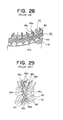
- Figures 27 and 28 are perspectives from a front end and a rear end, respectively, of part of a stator winding of a conventional alternator of this type
- Figure 29 is a perspective showing a construction of a conductor segment used in the stator winding of the conventional alternator shown in Figures 27 and 28.
- a stator 90 is constituted by a stator core 91, a stator winding 92 constituted by a number of electrical conductors disposed inside slots 91a formed in the stator core 91, and insulators 93 providing electrical insulation between the stator core 91 and the electrical conductors.
- stator core 91 of this conventional example ninety-six slots 91a are disposed at even pitch so as to house two three-phase alternating current windings such that the number of slots housing each phase portion of the three-phase alternating current windings corresponds to the number of magnetic poles in a rotor.
- Four electrical conductors are housed within each of the slots 91a so as to line up in one row in a radial direction, and these electrical conductors are connected in a predetermined winding pattern to form the stator winding 92.
- a first position, a second position, a third position, and a fourth position in a radial direction from an inner circumferential side inside the slots 91a in which the electrical conductors are housed will be called a first address, a second address, a third address, and a fourth address, respectively.
- Large segments 95 and small segments 96 are formed by bending short lengths of a conductor such as copper into general U shapes in which pairs of straight portions 95a and 96a are linked by turn portions 95b and 96b.
- the small segments 96 are inserted one at a time from a rear end into pairs of slots 91a six slots apart (a pitch of one magnetic pole).
- the large segments 95 are inserted one at a time from the rear end into pairs of slots 91a six slots apart (a pitch of one magnetic pole).
- end portions of the large segments 95 and the small segments 96 extending outwards at a front end are joined to each other to constitute the stator winding 92.
- the small segments 96 are inserted from the rear end into the second address within first slots 91a and into the third address within second slots 91a, and the large segments 95 are inserted from the rear end into the first address within the first slots 91a and into the fourth address within the second slots 91a.
- two straight portions 95a of the large segments 95 and two straight portions 96a of the small segments 96 are disposed to line up in a row of four in a radial direction.
- end portions 95c of the large segments 95 extending outwards at the front end from the first address within the first slots 91a are joined to end portions 96c of the small segments 96 extending outwards at the front end from the second address within the second slots 91a six slots away in a clockwise direction from the first slots 91a.
- the end portions 95c of the large segments 95 extending outwards at the front end from the fourth address within the first slots 91a are joined to the end portions 96c of the small segments 96 extending outwards at the front end from the third address within the second slots 91a six slots away in a counter-clockwise direction from the first slots 91a.
- two winding sub-portions are formed, which are lap windings having two turns per lap. These two winding sub-portions are connected in series to form one winding phase portion having four turns.
- a total of six winding phase portions each having four turns are formed by offsetting by one slot at a time the positions of the slots into which the large segments 95 and the small segments 96 are inserted. Then, three each of these winding phase portions are connected into each of the two three-phase alternating current windings which constitute the stator winding 92.
- the turn portions 95b of the large segments 95 are disposed so as to cover outer circumferential sides of the turn portions 96b of the small segments 96 inserted into the same pairs of slots 91a.
- the turn portions 95b and 96b are disposed circumferentially to constitute a rear-end coil end group.
- joint portions formed by joining the end portions 95c and 96c to each other are disposed circumferentially in two rows in a radial direction to constitute a front-end coil end group.
- stator winding 92 of the conventional alternator is constructed by inserting the large segments 95 and the small segments 96 formed by bending the short lengths of conductor into general U shapes into the slots 91a of the stator core 91 from the rear end and joining together the end portions of the segments extending outwards at the front end as explained above, one problem has been that a large number of the large segments 95 and the small segments 96 must be inserted into the slots 91a of the stator core 91 and end portions thereof must be joined one by one, significantly reducing workability and decreasing mass-producibility.
- the present invention aims to solve the above problems and an object of the present invention is to provide a winding assembly for an alternator and a method of manufacture therefor enabling mass-producibility to be improved and size to be reduced.
- Another objective is to provide an alternator enabling coil end height to be lowered, enabling the number of weld portions on the coil ends to be decreased, and enabling deterioration in output, wind noise and magnetic noise to be suppressed.
- an alternator including:
- Four of the strands of wire constituting the winding sub-portions may be housed so as to line up in each of the slots so as to occupy a first layer, a second layer, a third layer, and a fourth layer in a slot depth direction;
- the strands of wire may be installed two at a time into slot sets constituted by slot groups disposed a predetermined number of slots apart, the two strands of wire installed in each of the slot sets constituting a first strand of wire and a second strand of wire, and the stator winding may be composed of a plurality of stator winding phase portions, each of the stator winding phase portions comprising:
- the strands of wire may be installed two at a time into slot sets constituted by slot groups disposed a predetermined number of slots apart, the two strands of wire installed in each of the slot sets constituting a first strand of wire and a second strand of wire, and
- the strands of wire may be installed two at a time into slot sets constituted by slot groups disposed a predetermined number of slots apart, the two strands of wire installed in each of the slot sets constituting a first strand of wire and a second strand of wire, and the stator winding may be composed of a plurality of stator winding phase portions, each of the stator winding phase portions comprising:
- Four of the strands of wire constituting the winding sub-portions may be housed so as to line up in each of the slots so as to occupy a first layer, a second layer, a third layer, and a fourth layer in a slot depth direction;
- a winding assembly for an alternator including a winding group composed of 2n winding sub-portions disposed at a pitch of p, each of the winding sub-portions being constructed by folding and bending one strand of wire formed from a continuous wire into a pattern, the pattern having:
- a winding assembly for an alternator, the winding assembly comprising a winding group composed of 2n winding sub-portions disposed at a pitch of p, each of the winding sub-portions being constructed by folding and bending one strand of wire formed from a continuous wire into a pattern, the pattern having:
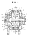
- Figure 1 is a cross section showing a construction of an alternator according to Embodiment 1 of the present invention
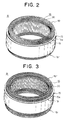
- Figures 2 and 3 are perspectives showing a stator of this alternator viewed from a rear end and a front end, respectively
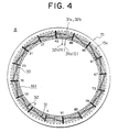
- Figure 4 is a rear end elevation explaining connections in one stator winding phase portion in this alternator
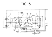
- Figure 5 is a circuit diagram for this alternator.
- Figures 6 to 9 are diagrams explaining a winding assembly forming process in a method of manufacture for the stator of the alternator according to Embodiment 1 of the present invention
- Figure 10 is a plan showing the winding assembly used in the stator of the alternator according to Embodiment 1 of the present invention.
- Figure 11 is a perspective showing the stator of the alternator according to Embodiment 1 of the present invention
- Figures 12A, 12B, and 12C are diagrams explaining the method of manufacture for the stator of the alternator according to Embodiment 1 of the present invention.
- crossover connections, neutral points, and output wires have been omitted.
- an automotive alternator is constructed by rotatably mounting a Lundell-type rotor 7 by means of a shaft 6 inside a case 3 constructed from an aluminum front bracket 1 and an aluminum rear bracket 2, and fastening a stator 8 to an inner wall of the case 3 so as to cover an outer circumferential side of the rotor 7.
- the shaft 6 is rotatably supported in the front bracket 1 and the rear bracket 2.
- a pulley 4 is fastened to a first end of this shaft 6 so that rotational torque from an engine can be transmitted to the shaft 6 by means of a belt (not shown).
- Slip rings 9 for supplying electric current to the rotor 7 are fastened to a second end of the shaft 6, and a pair of brushes 10 are housed in a brush holder 11 disposed inside the case such that the pair of brushes 10 slide in contact with the slip rings 9.
- a regulator 18 for adjusting the magnitude of alternating voltage generated in the stator 8 is fastened by adhesive to a heat sink 17 fitted onto the brush holder 11.
- Rectifiers 12 which are electrically connected to the stator 8 and convert alternating current generated in the stator 8 into direct current are mounted inside the case 3.
- the rotor 7 is composed of a rotor coil 13 for generating magnetic flux on passage of electric current, and a pair of pole cores 20 and 21 disposed so as to cover the rotor coil 13, magnetic poles being formed in the pole cores 20 and 21 by magnetic flux generated in the rotor coil 13.
- the pair of pole cores 20 and 21 are made of iron, each has eight claw-shaped magnetic poles 22 and 23 disposed on an outer circumferential perimeter at even pitch in a circumferential direction so as to project axially, and the pole cores 20 and 21 are fastened to the shaft 6 facing each other such that the claw-shaped magnetic poles 22 and 23 intermesh.
- fans 5 are fastened to first and second axial ends of the rotor 7.
- Front-end and rear-end air intake openings la and 2a are disposed in axial end surfaces of the front bracket 1 and the rear bracket 2, and front-end and rear-end air discharge openings 1b and 2b are disposed in two outer circumferential shoulder portions of the front bracket 1 and the rear bracket 2, opposite the radial outside of front-end and rear-end coil ends 16f and 16r of the stator winding 16.
- the stator 8 includes: a cylindrical stator core 15 composed of a laminated core formed with a number of slots 15a extending axially at a predetermined pitch in a circumferential direction; a stator winding 16 wound onto the stator core 15; and insulators 19 installed in each of the slots 15a for electrically insulating the stator winding 16 from the stator core 15.
- the stator winding 16 includes a number of winding sub-portions in each of which one strand of wire 30 is folded over outside the slots 15a at end surfaces of the stator core 15 and wound so as to alternately occupy an inner layer and an outer layer in a slot depth direction within slots 15a a predetermined number of slots apart, being wound into a lap winding having two turns in each lap.
- four strands of wire 30 are disposed in one row in the slot depth direction within each of the slots 15a, turn portions of the strands of wire 30 which are formed by being folded over outside the slots 15a at the front end of stator core 15 being disposed in a circumferential direction so as to be aligned in two rows in a radial direction constituting the front-end coil end group 16f, and turn portions of the strands of wire 30 which are formed by being folded over outside the slots 15a at the rear end of stator core 15 being disposed in a circumferential direction so as to overlap in two layers in an axial direction constituting the rear-end coil end group 16r.
- the stator core 15 is formed with ninety-six slots 15a at even pitch so as to house two three-phase alternating-current windings 160 such that the number of slots housing each phase portion of the alternating-current windings 160 corresponds to the number of magnetic poles (sixteen) in the rotor 7. In other words, there are two slots per pole per phase.
- One stator winding phase portion 161 is constituted by first and second winding sub-portions 31 and 32 each composed of one strand of wire 30.
- the first winding sub-portion 31 is constructed into a lap winding having two turns per lap in which, in pairs of slots constituted by Slot Numbers (12m + 1) and Slot Numbers (12m + 7) of the slots 15a, one strand of wire 30 is passed from the rear end to the front end in the first address of Slot Numbers (12m + 1) of the slots 15a, then passed from the front end to the rear end in the second address of Slot Numbers (12m + 7) of the slots 15a, thereafter passed from the rear end to the front end in the third address of Slot Numbers (12m + 1) of the slots 15a, and then passed from the front end to the rear end in the fourth address of Slot Numbers (12m + 7) of the slots 15a.
- m 0, 1, 2, ... 7.
- the second winding sub-portion 32 is constructed into a lap winding having two turns per lap in which, in pairs of slots constituted by Slot Numbers (12m + 7) and Slot Numbers ⁇ 12 (m + 1) + 1 ⁇ of the slots 15a, one strand of wire 30 is passed from the rear end to the front end in the first address of Slot Numbers (12m + 7) of the slots 15a, then passed from the front end to the rear end in the second address of Slot Numbers ⁇ 12 (m + 1) + 1 ⁇ of the slots 15a, thereafter passed from the rear end to the front end the third address of Slot Numbers (12m + 7) of the slots 15a, and then passed from the front end to the rear end in the fourth address of Slot Numbers ⁇ 12 (m + 1) + 1 ⁇ of the slots 15a.
- Slot Number 97 corresponds to Slot Number 1.
- each of the first and second winding sub-portions 31 and 32 constitutes a winding sub-portion in which a single strand of wire 30 is wound into a lap winding having two turns per lap so as to alternately occupy an inner layer and an outer layer in a slot depth direction in every sixth slot 15a.
- Four strands of wire 30 are disposed to line up in one row in a radial direction within each slot 15a with the longitudinal direction of the rectangular cross sections thereof aligned in a radial direction.
- the turn portion of the first winding sub-portion 31 linking the fourth address of Slot Number 43 and the first address of Slot Number 49 is cut, and the turn portion of the second winding sub-portion 32 linking the third address of Slot Number 43 and the second address of Slot Number 49 is also cut.
- a first cut end 31a of the first winding sub-portion 31 extending from the fourth address of Slot Number 43 and a second cut end 32b of the second winding sub-portion 32 extending from the second address of Slot Number 49 are crossover-connected by arc welding, for example, to connect the first and second winding sub-portions 31 and 32 in series.
- a stator winding phase portion 161 having four turns is formed.
- a first cut end 32a of the second winding sub-portion 32 extending from the third address of Slot Number 43 and a second cut end 31b of the first winding sub-portion 31 extending from the first address of Slot Number 49 become a neutral point (N) and an output wire (O), respectively, of the stator winding phase portion 161.
- stator winding phase portions 161 are formed by installing the strands of wire 30 into the stator core 15 such that the slots 15a into which the strands of wire 30 are inserted are offset by one slot at a time and connecting the strands of wire 30.
- stator 8 obtained includes the stator winding 16 which is wound into the stator core 15 as shown in Figures 2 and 3.
- the two three-phase alternating-current windings 160 are constructed by star-connecting such that the three stator winding phase portions 161 therein have a phase difference corresponding to an electrical angle of 120° from each other. Furthermore, the two three-phase alternating-current windings 160 are wound onto the stator core 15 so as to have a phase difference of 30° from each other. Each of these two three-phase alternating-current windings 160 is connected to its own rectifier 12. The rectifiers 12 are connected in parallel such that the direct-current output from each is combined.
- the stator winding phase portions 161 constituting the stator winding 16 include the first and second winding sub-portions 31 and 32 which are each formed by one strand of wire 30.
- the first and second winding sub-portions 31 and 32 are each formed into a lap winding having two turns per lap by winding one strand of wire 30 in order one turn at a time into pairs of slots, the slots in each pair being six slots apart and each pair being disposed at a pitch of twelve slots, the first and second winding sub-portions 31 and 32 also being formed so as to alternately occupy an inner layer and an outer layer in a slot depth direction in every sixth slot 15a.
- Four strands of wire 30 are disposed to line up in one row in a slot depth direction within each slot 15a.
- the turn portions of the strands of wire 30 which link different layers in slots 15a six slots apart at the end surfaces of the stator core 15 constitute the coil ends.
- the turn portions linking the first address (a first layer) to the second address (a second layer) and the turn portions linking the third address (a third layer) to the fourth address (a fourth layer) are formed into a substantially identical shape, mutually spaced circumferentially and radially, and disposed neatly in a circumferential direction in two rows to form the front-end coil end group 16f.
- the turn portions linking the first address (the first layer) to the fourth address (the fourth layer) and the turn portions linking the second address (the second layer) to the third address (the third layer) are mutually spaced in an axial direction and formed into two layers, mutually spaced circumferentially, and disposed neatly in a circumferential direction to form the rear-end coil end group 16r.
- the coil ends are constituted by the turn portions of the strands of wire 30, that is, by continuous wires, the number of joints can be significantly reduced, enabling the coil end height to be lowered, softening of the strands of wire 30 due to temperature increases during welding to be reduced, and reductions in rigidity of the stator to be suppressed compared to the conventional stator 90 in which the coil ends are constructed by clamping portions of the end portions 95c and 96c of the U-shaped large segments 95 and the small segments 96 in a jig and welding the end portions 95c and 96c together.
- an alternator can be provided in which coil leakage reactance in the coil end portions is reduced, improving output, wind resistance is reduced, alleviating wind noise, and deterioration in rigidity is reduced, reducing magnetic noise, compared to an alternator mounted with the conventional stator 90.
- the coil end groups 16f and 16r can be formed into a generally identical shape circumferentially, suppressing circumferential irregularities on radially inner edge surfaces of the coil end groups 16f and 16r, enabling wind noise generated between the rotor 7 and the coil end groups 16a and 16b to be reduced
- first and second straight portions 30a and 30b are offset at a pitch of six slots (6p) on a first side in a direction of disposal of the strands of wire 30 and linked by first inclined portions 30e
- the second and third straight portions 30b and 30c are offset at a pitch of six slots (6p) on a second side in the direction of disposal of the strands of wire 30 and linked by second inclined portions 30f
- the third and fourth straight portions 30c and 30d are offset at a pitch of six slots (6p
- a flattened cylindrical body 40 is formed in which the second and third straight portions 30b and 30c which are linked by the second inclined portions 30f and the fourth and first straight portions 30d and 30a which are linked by the fourth inclined portions 30h are wound helically so as to alternately occupy a first plane and a second plane by folding over the first and third inclined portions 30e and 30g in the same direction at central portions thereof.
- this cylindrical body 40 is constructed by arranging the second and third straight portions 30b and 30c, which are linked by the second inclined portions 30f, at a pitch of one slot in the first plane, and arranging the fourth and first straight portions 30d and 30a, which are linked by the fourth inclined portions 30h, at a pitch of one slot in the second plane.
- terminal processing is performed by cutting six of the third straight portions 30c at central portions A at a first end portion of the cylindrical body 40, and cutting six of the second straight portions 30b at central portions B at a second end portion of the cylindrical body 40 to form connecting portions with other end portions of the strands of wire 30.
- a winding assembly 41 shown in Figure 10, is prepared by folding over the cylindrical body 40 at central portions of the second inclined portions 30f and the fourth inclined portions 30h which are disposed at a pitch of one slot such that the second straight portions 30b and the third straight portions 30c face each other, as indicated by arrows in Figures 8 and 9.
- the first to fourth straight portions 30a to 30d are disposed at a pitch p so as to be lined up in four layers at a pitch w equal to the width of the strands of wire 30 in the width direction of the strands of wire 30, on a first side of which the folded first inclined portions 30e, which function as first turn portions, and the folded third inclined portions 30g, which function as third turn portions, are disposed at a pitch of one slot in the direction of disposal of the straight portions to form two rows.
- the folded second inclined portions 30f, which function as second turn portions, and the folded fourth inclined portions 30h, which function as fourth turn portions are disposed at a pitch of one slot in the direction of disposal of the straight portions to form two layers.
- lead portions of the output wires and the neutral points extend outwards from the fourth inclined portions 30h of the winding assembly 41, and these lead portions are formed by drawing out specific strands of wire 30 during the process of folding and bending the strands of wire 30 into the lightning-bolt shape.
- a parallelepiped laminated core 42 is prepared as shown in Figure 11 by laminating a predetermined number of sheets of SPCC material which is a magnetic material formed with trapezoidal slots 42a at a predetermined pitch (an electrical angle of 30°) and laser welding an outer portion thereof.
- the insulators 19 are mounted in the slots 42a of the laminated core 42, and the first to fourth straight portions 30a to 30d of the winding assembly 41 are inserted so as to stack up within each of the slots 42a.
- the winding assembly 41 is installed in the laminated core 42 as shown in Figure 12B.
- straight portions of the strands of wire 30 are housed in lines of four in a radial direction within the slots 42a and are electrically insulated from the laminated core 42 by the insulators 19.
- the laminated core 42 is rolled up and its ends abutted and welded to each other to obtain the cylindrical stator core 15, as shown in Figure 12C.
- first and second winding sub-portions 31 and 32 which are wound into slot groups disposed at a pitch of six slots each form lap windings having two turns per lap.
- the two three-phase alternating-current windings 160 are obtained by cutting each of the lead portions of the winding assembly 41, forming the crossover connections, then connecting the neutral points.
- stator 8 obtained is formed by installing the stator winding 16 composed of the two three-phase alternating-current windings 160 into the stator core 15.
- the winding assembly 41 is formed by arranging the twelve strands of wire 30 in the same plane at a pitch of one slot, folding and bending the twelve strands of wire 30 to form the lightning-bolt shaped pattern shown in Figures 6 and 7, forming the cylindrical body 40 in which the second and third straight portions 30b and 30c which are linked by the second inclined portions 30f and the fourth and first straight portions 30d and 30a which are linked by the fourth inclined portions 30h are wound helically by folding back the first and third inclined portions 30e and 30g in the same direction at central portions thereof, and then folding the cylindrical body 40 over at central portions of the second and fourth inclined portions 30f and 30h, a winding assembly can be easily manufactured which alternately occupies an inner layer and an outer layer in a slot depth direction in every sixth slot 15a and constitutes a lap winding having two turns per lap.
- stator winding phase portions 161 can be installed into the stator core 15 by installing one winding assembly 41 into the stator core 15.
- the complex operation of inserting a large number of segments into the slots of the stator core and joining the end portions thereof together one by one is no longer required, significantly improving assembly and workability, thereby enabling producibility to be increased.
- cases in which the number of turns in the stator winding is increased can easily be adapted for by stacking and installing a plurality of the winding assemblies 41 into the stator core 15.
- the coil ends are constituted by the turn portions of the strands of wire 30, the number of joints in the coil end groups 16f and 16r is significantly reduced. Thus, there is no need to extend the coil ends out by an extra amount from the end surfaces of the stator core 15, enabling the stator 8 to be reduced in size.
- the occurrence of short-circuiting accidents which accompany loss of insulation due to the joining process can be suppressed, superior insulation can be obtained and high yield can also be achieved.
- reductions in resistance to corrosion which accompany loss of insulation due to joining can be suppressed.
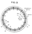
- Figure 13 is a rear end elevation explaining connections in one stator winding phase portion described in Japanese Patent Application No. 2000-011704.
- one stator winding phase portion 80 is composed of first to fourth winding sub-portions 81 to 84 each formed from one strand of wire 30.
- the first winding sub-portion 81 is constructed by wave winding one strand of wire 30 into every sixth slot from Slot Numbers 1 to 91 so as to alternately occupy the first address and the second address inside the slots 15a.
- the second winding sub-portion 82 is constructed by wave winding a strand of wire 30 into every sixth slot from Slot Numbers 1 to 91 so as to alternately occupy the second address and the first address inside the slots 15a.
- the third winding sub-portion 83 is constructed by wave winding a strand of wire 30 into every sixth slot from Slot Numbers 1 to 91 so as to alternately occupy the third address and the fourth address inside the slots 15a.
- the fourth winding sub-portion 84 is constructed by wave winding a strand of wire 30 into every sixth slot from Slot Numbers 1 to 91 so as to alternately occupy the fourth address and the third address inside the slots 15a.
- each of the first to fourth winding sub-portions 81 to 84 constitutes a winding sub-portion having one turn in which a single strand of wire 30 is wound into every sixth slot 15a so as to alternately occupy an inner layer and an outer layer in a slot depth direction.
- stator winding phase portions 80 are formed by offsetting the slots 15a into which the strands of wire 30 are wound by one slot each.
- a crossover connection (adjacent-address crossover connection C 2-3 ) is formed between a second end portion 81b of the first winding sub-portion 81 extending outwards from the second address of Slot Number 67 and a first end portion 83a of the third winding sub-portion 83 extending outwards from the third address of Slot Number 61
- a crossover connection (adjacent-address crossover connection C 2-3 ) is formed between a second end portion 82b of the second winding sub-portion 82 extending outwards from the second address of Slot Number 61 and a first end portion 84a of the fourth winding sub-portion 84 extending outwards from the third address of Slot Number 55
- a crossover connection (same-address crossover connection C 1-1 ) is formed between a first end portion 81a of the first winding sub-portion 81 extending outwards from the first address of Slot Number 61 and a first end portion 82a of
- a second end portion 83b of the third winding sub-portion 83 extending outwards from the fourth address of Slot Number 67 and a second end portion 84b of the fourth winding sub-portion 84 extending outwards from the fourth address of Slot Number 61 become an output wire (Oa) and a neutral point (Na), respectively, of one stator winding phase portion 80.
- stator winding phase portion 80 of this comparative example is constituted by the first to fourth winding sub-portions 81 to 84 having one turn in each of which one strand of wire 30 is wound into a wave winding so as to alternately occupy an inner layer and an outer layer in a slot depth direction in every sixth slot 15a, the complex operation of inserting a large number of segments into the slots of the stator core and joining the end portions thereof together one by one is no longer required, significantly improving assembly and workability, thereby enabling producibility to be increased.
- the coil ends are constituted by the turn portions of the strands of wire 30, the number of joints in the coil end groups is significantly reduced. Thus, there is no need to extend the coil ends out by an extra amount from the end surfaces of the stator core 15, enabling the stator to be reduced in size.
- this stator winding phase portion 80 is constituted by the first to fourth winding sub-portions 81 to 84 which are each formed by winding one strand of wire 30 into a wave winding, three crossover connections are required in order to connect the first to fourth winding sub-portions 81 to 84 in series.
- stator winding phase portions 161 in Embodiment 1 of the present invention are each constituted by the first and second winding sub-portions 31 and 32 which are each formed by winding one strand of wire 30 into a lap winding having two turns per lap, one crossover connection is sufficient to connect the first and second winding sub-portions 31 and 32 in series, and it can be seen that the connecting operation can be improved compared to the comparative example. Furthermore, by reducing the number of crossover connections and simplifying the connecting portions, wind noise as a result of circumferential irregularities in the rear-end coil end group 16r is suppressed, enabling noise reductions to be achieved. In addition, because wind resistance in the rear-end coil end group 16r is lessened by reducing the number of crossover connections and simplifying the connecting portions, the volume of air flow increases proportionally, improving the cooling effect.
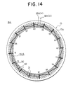
- Figure 14 is a front end elevation explaining connections in one stator winding phase portion in an automotive alternator according to Embodiment 2 of the present invention.
- the rear-end wiring of the strands of wire is indicated by solid lines
- the front-end wiring of the strands of wire is indicated by broken lines
- the connecting portions of the strands of wire are indicated by black dots.
- One stator winding phase portion 161A is constituted by first and second winding sub-portions 31 and 32 each composed of one strand of wire 30.
- the first winding sub-portion 31 is constructed into a lap winding having two turns per lap in which, in pairs of slots constituted by Slot Numbers (12m + 1) and Slot Numbers (12m + 7) of the slots 15a, one strand of wire 30 is passed from the front end to the rear end in the first address of Slot Numbers (12m + 1) of the slots 15a, then passed from the rear end to the front end in the second address of Slot Numbers (12m + 7) of the slots 15a, thereafter passed from the front end to the rear end in the third address of Slot Numbers (12m + 1) of the slots 15a, and then passed from the rear end to the front end in the fourth address of Slot Numbers (12m + 7) of the slots 15a.
- m 0, 1, 2, ... 7.
- the second winding sub-portion 32 is constructed into a lap winding having two turns per lap in which, in pairs of slots constituted by Slot Numbers (12m + 7) and Slot Numbers ⁇ 12 (m + 1) + 1 ⁇ of the slots 15a, one strand of wire 30 is passed from the front end to the rear end in the first address of Slot Numbers (12m + 7) of the slots 15a, then passed from the rear end to the front end in the second address of Slot Numbers ⁇ 12 (m + 1) + 1 ⁇ of the slots 15a, thereafter passed from the front end to the rear end the third address of Slot Numbers (12m + 7) of the slots 15a, and then passed from the rear end to the front end in the fourth address of Slot Numbers ⁇ 12 (m + 1) + 1 ⁇ of the slots 15a.
- Slot Number 97 corresponds to Slot Number 1.
- each of the first and second winding sub-portions 31 and 32 constitutes a winding sub-portion in which a single strand of wire 30 is wound into a lap winding having two turns per lap so as to alternately occupy an inner layer and an outer layer in a slot depth direction in every sixth slot 15a.
- a winding portion having 4 turns in which the first and second winding sub-portions 31 and 32 are connected in series is obtained by joining a first end portion of the first winding sub-portion 31 extending towards the front end from the first address of Slot Number 1 to a second end portion of the second winding sub-portion 32 extending towards the front end from the third address of Slot Number 91, and by then joining a first end portion of the second winding sub-portion 32 extending towards the front end from the second address of Slot Number 1 to a second end portion of the first winding sub-portion 31 extending towards the front end from the fourth address of the Slot Number 91.
- the turn portion of the second winding sub-portion 32 linking the third address of Slot Number 43 and the fourth address of Slot Number 49 is cut to form one stator winding phase portion 161A having four turns in which a first cut end 32a of the second winding sub-portion 32 extending from the third address of Slot Number 43 and a second cut end 32b of the second winding sub-portion 32 extending from the fourth address of Slot Number 49 become a neutral point (N) and an output wire (O), respectively.
- stator winding phase portions 161A are formed by installing the strands of wire 30 into the stator core 15 such that the slots 15a into which the strands of wire 30 are inserted are offset by one slot at a time and connecting the strands of wire 30.
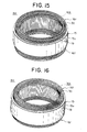
- a stator 8A obtained includes a stator winding 16A which is wound into the stator core 15 as shown in Figures 15 and 16.
- Figure 15 is a perspective showing the stator viewed from the rear end
- Figure 16 is a perspective showing the stator viewed from the front end. The neutral points and the output wires have been omitted from these figures.
- the stator winding phase portions 161A constituting the stator winding 16A are constituted by the first and second winding sub-portions 31 and 32 which are each formed into a lap winding having two turns per lap by winding one strand of wire 30 in order one turn at a time into pairs of slots, the slots in each pair being six slots apart and the pairs of slots being disposed at a pitch of twelve slots, the first and second winding sub-portions 31 and 32 also being formed so as to alternately occupy an inner layer and an outer layer in a slot depth direction in every sixth slot 15a.
- Four strands of wire 30 are disposed to line up in one row in a slot depth direction within each slot 15a.
- the turn portions of the strands of wire 30 which link different layers in slots 15a six slots apart at the end surfaces of the stator core 15 constitute the coil ends.
- Embodiment 2 Consequently, similar effects to those in Embodiment 1 above can also be obtained in Embodiment 2.
- the first and second winding portions 31 and 32 are connected in series to form the winding portion having 4 turns by joining the first end portion of the first winding sub-portion 31 to the second end portion of the second winding sub-portion 32, and joining the first end portion of the second winding sub-portion 32 to the second end portion of the first winding sub-portion 31.
- one portion of the second winding sub-portion 32 extending outwards at the rear end in each phase is cut after the first and second winding sub-portions 31 and 32 are installed into the stator core 15, and the cut ends thereof can be used as the neutral point and the output wire, improving workability.
- a coil end group in which the turn portions constituted by folded portions of the strands of wire 30 are disposed circumferentially to form two rows in a radial direction is disposed at the rear end, wind resistance is reduced in a wind channel at the rear end where rectifiers 12 and a regulator 18 which are heat-generating parts are mounted, enabling the rectifiers 12 and the regulator 18 to be cooled efficiently.
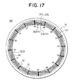
- Figure 17 is a rear end elevation explaining connections in one stator winding phase portion in an automotive alternator according to Embodiment 3 of the present invention
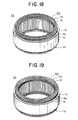
- Figures 18 and 19 are perspectives showing a stator of this alternator viewed from the rear end and the front end respectively.
- the rear-end wiring of the strands of wire is indicated by solid lines
- the front-end wiring of the strands of wire is indicated by broken lines
- the connecting portions of the strands of wire are indicated by black dots.
- neutral points and output wires have been omitted.
- one stator winding phase portion 161B is constituted by first and second winding sub-portions 31 and 32 each composed of one strand of wire 30.
- the first winding sub-portion 31 is constructed into a lap winding having two turns per lap in which, in pairs of slots constituted by Slot Numbers (12m + 1) and Slot Numbers (12m + 7) of the slots 15a, one strand of wire 30 is passed from the rear end to the front end in the fourth address of Slot Numbers (12m + 1) of the slots 15a, then passed from the front end to the rear end in the first address of Slot Numbers (12m + 7) of the slots 15a, thereafter passed from the rear end to the front end in the second address of Slot Numbers (12m + 1) of the slots 15a, and then passed from the front end to the rear end in the third address of Slot Numbers (12m + 7) of the slots 15a.
- m 0, 1, 2, ... 7.
- the second winding sub-portion 32 is constructed into a lap winding having two turns per lap in which, in pairs of slots constituted by Slot Numbers (12m + 7) and Slot Numbers ⁇ 12 (m + 1) + 1 ⁇ of the slots 15a, one strand of wire 30 is passed from the rear end to the front end in the fourth address of Slot Numbers (12m + 7) of the slots 15a, then passed from the front end to the rear end in the first address of Slot Numbers ⁇ 12 (m + 1) + 1 ⁇ of the slots 15a, thereafter passed from the rear end to the front end the second address of Slot Numbers (12m + 7) of the slots 15a, and then passed from the front end to the rear end in the third address of Slot Numbers ⁇ 12 (m + 1) + 1 ⁇ of the slots 15a.
- Slot Number 97 corresponds to Slot Number 1.
- each of the first and second winding sub-portions 31 and 32 constitutes a winding sub-portion in which a single strand of wire 30 is wound into a lap winding having two turns per lap so as to alternately occupy an inner layer and an outer layer in a slot depth direction in every sixth slot 15a.
- the turn portion of the first winding sub-portion 31 linking the third address of Slot Number 43 and the fourth address of Slot Number 49 is cut, and the turn portion of the second winding sub-portion 32 linking the second address of Slot Number 43 and the first address of Slot Number 49 is also cut.
- a first cut end 31a of the first winding sub-portion 31 extending from the third address of Slot Number 43 and a second cut end 32b of the second winding sub-portion 32 extending from the first address of Slot Number 49 are crossover-connected by arc welding, for example, to connect the first and second winding sub-portions 31 and 32 in series.
- a stator winding phase portion 161B having four turns is formed.
- a first cut end 32a of the second winding sub-portion 32 extending from the second address of Slot Number 43 and a second cut end 31b of the first winding sub-portion 31 extending from the fourth address of Slot Number 49 become a neutral point (N) and an output wire (O), respectively, of the stator winding phase portion 161B.
- stator winding phase portions 161B are formed by installing the strands of wire 30 into the stator core 15 such that the slots 15a into which the strands of wire 30 are inserted are offset by one slot at a time and connecting the strands of wire 30.
- a stator 8B is obtained which includes a stator winding 16B which is wound into the stator core 15 as shown in Figures 18 and 19.
- the stator winding phase portions 161B constituting the stator winding 16B are constituted by the first and second winding sub-portions 31 and 32 which are each formed into a lap winding having two turns per lap by winding one strand of wire 30 in order one turn at a time into pairs of slots, the slots in each pair being six slots apart and the pairs of slots being disposed at a pitch of twelve slots, the first and second winding sub-portions 31 and 32 also being formed so as to alternately occupy an inner layer and an outer layer in a slot depth direction in every sixth slot 15a.
- Four strands of wire 30 are disposed to line up in one row in a slot depth direction within each slot 15a.
- the turn portions of the strands of wire 30 which link different layers in slots 15a six slots apart at the end surfaces of the stator core 15 constitute the coil ends.
- Embodiment 3 because a coil end group in which the turn portions constituted by folded portions of the strands of wire 30 are disposed circumferentially to form two rows in a radial direction is disposed at the rear end, wind resistance is reduced in a wind channel at the rear end where rectifiers 12 and a regulator 18 which are heat-generating parts are mounted, enabling the rectifiers 12 and the regulator 18 to be cooled efficiently.
- first and second straight portions 30a and 30b are offset at a pitch of six slots (6p) on a first side in a direction of disposal of the strands of wire 30 and linked by first inclined portions 30e
- the second and third straight portions 30b and 30c are offset at a pitch of six slots (6p) on the first side in the direction of disposal of the strands of wire 30 and linked by second inclined portions 30f
- the third and fourth straight portions 30c and 30d are offset at a pitch of six slots (6p) on a second side in
- a flattened cylindrical body 40B is formed in which the second and third straight portions 30b and 30c which are linked by the second inclined portions 30f and the fourth and first straight portions 30d and 30a which are linked by the fourth inclined portions 30h are wound helically so as to alternately occupy a first plane and a second plane by folding back the first and third inclined portions 30e and 30g in the same direction at central portions thereof.
- this cylindrical body 40B is constructed by arranging the second and third straight portions 30b and 30c, which are linked by the second inclined portions 30f, at a pitch of one slot in the first plane, and arranging the fourth and first straight portions 30d and 30a, which are linked by the fourth inclined portions 30h, at a pitch of one slot in the second plane.
- terminal processing is performed by cutting six of the third straight portions 30d at central portions A at a first end portion of the cylindrical body 40B, and cutting six of the second straight portions 30c at central portions B at a second end portion of the cylindrical body 40 to form connecting portions with other end portions of the strands of wire 30.
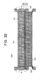
- a winding assembly 41B shown in Figure 23, is prepared by folding over the cylindrical body 40B at central portions of the second inclined portions 30f and the fourth inclined portions 30h which are disposed at a pitch of one slot, such that the second straight portions 30b and the third straight portions 30c face each other, as indicated by arrows in Figure 22.
- the first to fourth straight portions 30a to 30d are disposed at a pitch p so as to be lined up in four layers at a pitch w equal to the width of the strands of wire 30 in the width direction of the strands of wire 30, on a first side of which the folded first inclined portions 30e, which function as first turn portions, and the folded third inclined portions 30g, which function as third turn portions, are disposed at a pitch of one slot in the direction of disposal of the straight portions to form two rows.
- the folded second inclined portions 30f, which function as second turn portions, and the folded fourth inclined portions 30h, which function as fourth turn portions are disposed at a pitch of one slot in the direction of disposal of the straight portions to form two layers.
- lead portions of the output wires and the neutral points extend outwards from the second and third inclined portions 30e and 30g of the winding assembly 41B, and these lead portions are formed by drawing out specific strands of wire 30 during the process of folding and bending the strands of wire 30 into the lightning-bolt shape.
- insulators 19 are mounted in slots 42a of a laminated core 42, and the first to fourth straight portions 30a to 30d of the winding assembly 41B are inserted so as to stack up within each of the slots 42a.
- the winding assembly 41B is installed in the laminated core 42 as shown in Figure 12B.
- the laminated core 42 is rolled up and its ends abutted and welded to each other to obtain the cylindrical stator core 15, as shown in Figure 12C.
- first and second winding sub-portions 31 and 32 which are wound into slot groups disposed at a pitch of six slots each form lap windings having two turns per lap.
- the two three-phase alternating-current windings are obtained by cutting each of the lead portions of the winding assembly 41B, forming crossover connections, then connecting the neutral points.
- stator 8B obtained is formed by installing the stator winding 16B composed of the two three-phase alternating-current windings in the stator core 15.
- the winding assembly 41B is formed by arranging the twelve strands of wire 30 in the same plane at a pitch of one slot, folding and bending the twelve strands of wire 30 to form the lightning-bolt shaped pattern shown in Figures 20 and 21, forming the cylindrical body 40B in which the second and third straight portions 30b and 30c which are linked by the second inclined portions 30f and the fourth and first straight portions 30d and 30a which are linked by the fourth inclined portions 30h are wound helically by folding back the first and third inclined portions 30e and 30g in the same direction at central portions thereof, and then folding the cylindrical body 40B over at central portions of the second and fourth inclined portions 30f and 30h, a winding assembly can be easily manufactured which alternately occupies an inner layer and an outer layer in a slot depth direction in every sixth slot 15a and constitutes a lap winding having two turns per lap.
- stator winding phase portions 161B can be installed into the stator core 15 by installing one winding assembly 41B into the stator core 15.
- the complex operation of inserting a large number of segments into the slots of the stator core and joining the end portions thereof together one by one is no longer required, significantly improving assembly and workability, thereby enabling producibility to be increased.
- cases in which the number of turns in the stator winding is increased can easily be adapted for by stacking and installing a plurality of the winding assemblies 41B into the stator core 15.
- the coil ends are constituted by the turn portions of the strands of wire 30, the number of joints in the coil end groups 16f and 16r is significantly reduced. Thus, there is no need to extend the coil ends out by an extra amount from the end surfaces of the stator core 15, enabling the stator 8B to be reduced in size.
- superior insulation can be obtained and high yield can also be achieved.
- reductions in resistance to corrosion which accompany loss of insulation due to joining can be suppressed.
- Figures 24 and 25 are perspectives showing a stator of the alternator according to Embodiment 4 of the present invention viewed from the rear end and the front end, respectively, and Figure 26 is a diagram explaining a winding assembly forming process in a method of manufacture for the stator of the alternator according to Embodiment 4 of the present invention.
- Figures 24 and 25 neutral points and output wires have been omitted.
- stator 8C In this stator 8C, four strands of wire 30 are housed so as to line up in a slot depth direction within the slots 15a as shown in Figures 24 and 25.
- first and second slots in which the slots forming each pair are six slots apart, the strand of wire 30 housed in the first address of the first slot 15a is folded back outside the slots at the front end of the stator core 15 and housed in the second address of the second slot 15a, and the strand of wire 30 housed in the fourth address of the first slot 15a is folded back outside the slots at the front end of the stator core 15 and housed in the third address of the second slot 15a.
- the strand of wire 30 housed in the fourth address of the first slot 15a is folded back outside the slots at the rear end of stator core 15 and housed in the second address of the second slot 15a, and the strand of wire 30 housed in the third address of the first slot 15a is folded over outside the slots at the rear end of the stator core 15 and housed in the first address of the second slot 15a.
- stator winding 16C is constituted by a plurality of winding sub-portions in each of which a single strand of wire 30 is wound into a lap winding having two turns per lap so as to alternately occupy an inner layer and an outer layer in a slot depth direction in every sixth slot 15a.
- Turn portions of the strands of wire 30 folded over outside the slots at the front end of the stator core 15 are disposed in a circumferential direction so as to form two rows in a radial direction and constitute a front-end coil end group 16f, and turn portions of the strands of wire 30 folded over outside the slots at the rear end of the stator core 15 are disposed in a circumferential direction so as to form one row in a radial direction and constitute a rear-end coil end group 16r.
- the winding assembly 41C formed by integrating a plurality of the winding sub-portions, is formed by folding back the cylindrical body 40C, in which the first to fourth straight portions 30a to 30d are wound helically, at central portions of the second and fourth inclined portions 30f and 30h as shown in Figure 26.
- turn portions of the strands of wire 30 in Embodiment 4 are disposed in a circumferential direction so as to form two rows in a radial direction and constitute the front-end coil end group 16f, and turn portions of the strands of wire 30 are disposed so as to form one row in a circumferential direction and constitute the rear-end coil end group 16r, the axial heights of the front-end and rear end-end groups 16f and 16r can be reduced.
- coil leakage reactance is further reduced, improving output, and wind resistance is reduced, alleviating wind noise, compared to each of the above embodiments.
- the number of slots in the stator was ninety-six slots for sixteen magnetic poles, but three phases and seventy-two slots for twelve magnetic poles, 120 slots for twenty poles, etc., may also be adopted. Furthermore, in the case of one slot per pole per phase, there may also be forty-eight slots for sixteen poles, thirty-six slots for twelve poles, sixty slots for twenty poles, etc.
- the present invention is constructed in the above manner and exhibits the effects described below.
- an alternator including:
- Four of the strands of wire constituting the winding sub-portions may be housed so as to line up in each of the slots so as to occupy a first layer, a second layer, a third layer, and a fourth layer in a slot depth direction;
- the strands of wire may be installed two at a time into slot sets constituted by slot groups disposed a predetermined number of slots apart, the two strands of wire installed in each of the slot sets constituting a first strand of wire and a second strand of wire, and the stator winding may be composed of a plurality of stator winding phase portions, each of the stator winding phase portions comprising:
- the strands of wire may be installed two at a time into slot sets constituted by slot groups disposed a predetermined number of slots apart, the two strands of wire installed in each of the slot sets constituting a first strand of wire and a second strand of wire, and
- the strands of wire may be installed two at a time into slot sets constituted by slot groups disposed a predetermined number of slots apart, the two strands of wire installed in each of the slot sets constituting a first strand of wire and a second strand of wire, and the stator winding may be composed of a plurality of stator winding phase portions, each of the stator winding phase portions comprising:
- Four of the strands of wire constituting the winding sub-portions may be housed so as to line up in each of the slots so as to occupy a first layer, a second layer, a third layer, and a fourth layer in a slot depth direction;
- a winding assembly for an alternator including a winding group composed of 2n winding sub-portions disposed at a pitch of p, each of the winding sub-portions being constructed by folding and bending one strand of wire formed from a continuous wire into a pattern, the pattern having:
- a winding assembly for an alternator, the winding assembly comprising a winding group composed of 2n winding sub-portions disposed at a pitch of p, each of the winding sub-portions being constructed by folding and bending one strand of wire formed from a continuous wire into a pattern, the pattern having:
Landscapes
- Engineering & Computer Science (AREA)
- Power Engineering (AREA)
- Manufacturing & Machinery (AREA)
- Windings For Motors And Generators (AREA)
- Manufacture Of Motors, Generators (AREA)
- Synchronous Machinery (AREA)
Priority Applications (1)
| Application Number | Priority Date | Filing Date | Title |
|---|---|---|---|
| EP06008093A EP1720233B1 (fr) | 2000-03-13 | 2000-12-08 | Enroulements du stator d'un alternateur |
Applications Claiming Priority (2)
| Application Number | Priority Date | Filing Date | Title |
|---|---|---|---|
| JP2000068762A JP4014071B2 (ja) | 2000-03-13 | 2000-03-13 | 交流発電機及びその巻線アッセンブリ並びに巻線アッセンブリの製造方法 |
| JP2000068762 | 2000-03-13 |
Related Child Applications (2)
| Application Number | Title | Priority Date | Filing Date |
|---|---|---|---|
| EP06008093A Division EP1720233B1 (fr) | 2000-03-13 | 2000-12-08 | Enroulements du stator d'un alternateur |
| EP06008093.4 Division-Into | 2006-04-19 |
Publications (3)
| Publication Number | Publication Date |
|---|---|
| EP1134872A2 true EP1134872A2 (fr) | 2001-09-19 |
| EP1134872A3 EP1134872A3 (fr) | 2004-04-28 |
| EP1134872B1 EP1134872B1 (fr) | 2012-05-02 |
Family
ID=18587768
Family Applications (2)
| Application Number | Title | Priority Date | Filing Date |
|---|---|---|---|
| EP00126510A Expired - Lifetime EP1134872B1 (fr) | 2000-03-13 | 2000-12-08 | Enroulements du stator d'un alternateur |
| EP06008093A Expired - Lifetime EP1720233B1 (fr) | 2000-03-13 | 2000-12-08 | Enroulements du stator d'un alternateur |
Family Applications After (1)
| Application Number | Title | Priority Date | Filing Date |
|---|---|---|---|
| EP06008093A Expired - Lifetime EP1720233B1 (fr) | 2000-03-13 | 2000-12-08 | Enroulements du stator d'un alternateur |
Country Status (4)
| Country | Link |
|---|---|
| US (2) | US6498413B2 (fr) |
| EP (2) | EP1134872B1 (fr) |
| JP (1) | JP4014071B2 (fr) |
| KR (1) | KR100411452B1 (fr) |
Cited By (9)
| Publication number | Priority date | Publication date | Assignee | Title |
|---|---|---|---|---|
| EP1331725A2 (fr) * | 2002-01-29 | 2003-07-30 | Mitsubishi Denki Kabushiki Kaisha | Dispositif d'alimentation de puissance éléctrique pour véhicule |
| GB2389717A (en) * | 2002-01-24 | 2003-12-17 | Visteon Global Tech Inc | Automotive alternator stator interlaced winding layout |
| GB2390486A (en) * | 2002-01-24 | 2004-01-07 | Visteon Global Tech Inc | Automotive alternator stator interlaced winding layout |
| WO2004047253A1 (fr) * | 2002-11-15 | 2004-06-03 | In Motion Technologies Pty Ltd | Dispositif electromagnetique pluriphase a disposition amelioree des enroulements conducteurs |
| US6885124B2 (en) | 2003-03-14 | 2005-04-26 | Visteon Global Technologies, Inc. | Stator winding having radial aligned wraps |
| US7170211B2 (en) | 2002-01-24 | 2007-01-30 | Visteon Global Technologies, Inc. | Stator winding having transitions |
| WO2007057355A1 (fr) * | 2005-11-21 | 2007-05-24 | Robert Bosch Gmbh | Enroulement parallele multiple replie pour stator |
| WO2008081020A2 (fr) * | 2006-12-29 | 2008-07-10 | Robert Bosch Gmbh | Générateur de courant alternatif comprenant un stator et un enroulement statorique, inclus dans des encoches statoriques, constitué d'éléments d'enroulement ainsi qu'un procédé pour la fabrication d'un stator selon la présente invention |
| US7679253B2 (en) | 2002-01-24 | 2010-03-16 | Visteon Global Technologies, Inc. | Stator assembly with cascaded winding and method of making same |
Families Citing this family (25)
| Publication number | Priority date | Publication date | Assignee | Title |
|---|---|---|---|---|
| EP1548914A3 (fr) * | 2000-11-06 | 2010-08-25 | Denso Corporation | Assemblage de stator pour machine électrique rotative |
| JP3566665B2 (ja) * | 2001-04-06 | 2004-09-15 | 三菱電機株式会社 | 回転電機の固定子 |
| US6787961B2 (en) * | 2002-12-19 | 2004-09-07 | Visteon Global Technologies, Inc. | Automotive alternator stator assembly with varying end loop height between layers |
| US6930426B2 (en) * | 2003-11-26 | 2005-08-16 | Visteon Global Technologies, Inc. | Alternator stator having a multiple filar construction to improve convective cooling |
| JP3786058B2 (ja) * | 2002-06-25 | 2006-06-14 | 株式会社デンソー | 回転電機のセグメント順次接合ステータコイルおよびその製造方法 |
| US6949857B2 (en) * | 2003-03-14 | 2005-09-27 | Visteon Global Technologies, Inc. | Stator of a rotary electric machine having stacked core teeth |
| JP3982446B2 (ja) * | 2003-04-16 | 2007-09-26 | 株式会社日立製作所 | 回転電機の製造方法 |
| US7081697B2 (en) * | 2004-06-16 | 2006-07-25 | Visteon Global Technologies, Inc. | Dynamoelectric machine stator core with mini caps |
| SE0401826D0 (sv) * | 2004-07-09 | 2004-07-09 | Trimble Ab | Method of preparing a winding for an n-phase motor |
| US7386931B2 (en) * | 2004-07-21 | 2008-06-17 | Visteon Global Technologies, Inc. | Method of forming cascaded stator winding |
| US7269888B2 (en) * | 2004-08-10 | 2007-09-18 | Visteon Global Technologies, Inc. | Method of making cascaded multilayer stator winding with interleaved transitions |
| US7687961B2 (en) * | 2005-03-01 | 2010-03-30 | Honda Motor Co., Ltd. | Stator, motor, and method of manufacturing such stator |
| JP2010527869A (ja) * | 2007-05-22 | 2010-08-19 | ティッセンクルップ・エレベーター・アーゲー | エレベータ駆動装置の電気駆動部 |
| US7539083B2 (en) * | 2007-06-25 | 2009-05-26 | The United States Of America As Represented By The Secretary Of The Navy | Remote voice detection system |
| US20090001831A1 (en) * | 2007-06-26 | 2009-01-01 | Cho Chahee P | Axial Field Electric Motor and Method |
| FR2947968A1 (fr) * | 2009-07-09 | 2011-01-14 | Valeo Equip Electr Moteur | Bobinage d'une machine electrique tournante |
| JP5425132B2 (ja) * | 2011-03-30 | 2014-02-26 | 三菱電機株式会社 | 回転電機 |
| US9071116B2 (en) | 2013-01-17 | 2015-06-30 | Remy Technologies, Llc | Apparatus for installing stator winding conductors |
| EP3427372B1 (fr) * | 2016-03-08 | 2022-06-22 | Grob-Werke GmbH & Co. KG | Procédé de fabrication d'un stator |
| WO2019152773A1 (fr) * | 2018-02-01 | 2019-08-08 | Borgwarner Inc. | Enroulement distribué de stator |
| KR20210031762A (ko) | 2018-08-10 | 2021-03-22 | 보그워너 인크. | 전자 기계 구성 요소의 권선 직조 방법 |
| US11316415B2 (en) | 2018-08-10 | 2022-04-26 | Borgwarner Inc. | Method of winding a stator of an electric machine |
| WO2020033857A1 (fr) | 2018-08-10 | 2020-02-13 | Borgwarner Inc. | Procédé de formation d'un composant pour une machine électrique |
| DE102019124162A1 (de) * | 2019-09-09 | 2021-03-11 | Schaeffler Technologies AG & Co. KG | Bandförmige Wicklungseinheit für eine Statorwicklung und Verfahren zur Herstellung einer bandförmigen Wicklungseinheit |
| DE102022116741A1 (de) | 2022-07-05 | 2024-01-11 | Schaeffler Technologies AG & Co. KG | Verfahren und Vorrichtung zur Torsionsvermeidung von Drähten bei der Herstellung von Wellenwicklungen |
Family Cites Families (34)
| Publication number | Priority date | Publication date | Assignee | Title |
|---|---|---|---|---|
| US2821641A (en) | 1956-04-16 | 1958-01-28 | Allis Chalmers Mfg Co | Strand transposition |
| US3805104A (en) * | 1969-07-10 | 1974-04-16 | Rajonot E Ets | Low inertia rotor for dynamo electric machines, and method of making the same |
| GB1545777A (en) * | 1976-06-02 | 1979-05-16 | Edgar J | Electric motors |
| DE2811249A1 (de) * | 1978-03-15 | 1979-09-20 | Kraftwerk Union Ag | Mehrebenen-leiterstab fuer elektrische maschinen, insbesondere fuer turbogeneratoren |
| DE3008212C2 (de) * | 1980-03-04 | 1985-06-27 | Robert Bosch Gmbh, 7000 Stuttgart | Verfahren zur Herstellung von Statorwicklungen für Dreiphasen-Drehstromgeneratoren |
| JPS63194543A (ja) * | 1987-02-09 | 1988-08-11 | Hitachi Ltd | 車両用交流発電機の固定子及びその製造方法 |
| JP2962868B2 (ja) * | 1991-06-17 | 1999-10-12 | 本田技研工業株式会社 | モータの電機子巻線構造 |
| US5382859A (en) * | 1992-09-01 | 1995-01-17 | Unique Mobility | Stator and method of constructing same for high power density electric motors and generators |
| US5708316A (en) * | 1992-10-23 | 1998-01-13 | Nippondenso Co., Ltd. | Altenator for a vehicle |
| DE4300764C2 (de) * | 1993-01-14 | 1997-09-04 | Reinhard Napierski | Verfahren und Vorrichtung zur Herstellung einer Wellenwicklung |
| US6066514A (en) * | 1996-10-18 | 2000-05-23 | Micron Technology, Inc. | Adhesion enhanced semiconductor die for mold compound packaging |
| JPH08298756A (ja) * | 1995-04-25 | 1996-11-12 | Toyota Motor Corp | モータのステータ作製方法およびステータコア |
| JP3346968B2 (ja) | 1995-10-06 | 2002-11-18 | 三菱電機株式会社 | 交流回転電機の固定子製造方法 |
| US5654602A (en) * | 1996-05-13 | 1997-08-05 | Willyoung; David M. | Generator winding |
| DE19633399A1 (de) * | 1996-08-19 | 1998-02-26 | Siemens Ag | Ein den Ständer einer elektrischen Maschine bildender Eisenkern |
| JP3568364B2 (ja) * | 1996-09-30 | 2004-09-22 | 松下電器産業株式会社 | 回転電機のコア |
| JP3680482B2 (ja) * | 1997-03-28 | 2005-08-10 | 松下電器産業株式会社 | 電動機の固定子構成部材、電動機の固定子、電動機の製造方法 |
| WO1998054822A1 (fr) * | 1997-05-26 | 1998-12-03 | Denso Corporation | Alternateur pour vehicule |
| EP0881756B1 (fr) * | 1997-05-26 | 2001-08-01 | Denso Corporation | Alternateur de véhicule automobile |
| US6137201A (en) | 1997-05-26 | 2000-10-24 | Denso Corporation | AC generator for vehicles |
| JP3303773B2 (ja) * | 1997-05-26 | 2002-07-22 | 株式会社デンソー | 車両用交流発電機の固定子 |
| EP1237254B1 (fr) * | 1997-05-26 | 2008-06-04 | Denso Corporation | Alternateur pour véhicules automobiles |
| JP2927288B2 (ja) | 1997-05-26 | 1999-07-28 | 株式会社デンソー | 車両用交流発電機 |
| CA2238504C (fr) * | 1997-05-26 | 2001-03-13 | Atsushi Umeda | Agencement du stator d'un alternateur pour vehicule |
| JP3407643B2 (ja) * | 1997-05-26 | 2003-05-19 | 株式会社デンソー | 車両用交流発電機 |
| US5955810A (en) * | 1997-05-26 | 1999-09-21 | Denso Corporation | Alternator for vehicle |
| US5952749A (en) * | 1997-05-26 | 1999-09-14 | Denso Corporation | Cooling arrangement of alternator |
| US6124660A (en) * | 1997-05-26 | 2000-09-26 | Denso Corporation | AC generator for vehicles |
| DE69830869T2 (de) * | 1997-05-26 | 2006-05-24 | Denso Corp., Kariya | Wechselstromgenerator für Kraftfahrzeuge |
| US5986375A (en) * | 1997-09-26 | 1999-11-16 | Denso Corporation | Alternator for vehicle |
| JP3952346B2 (ja) * | 1998-05-20 | 2007-08-01 | 株式会社デンソー | 回転電機及びその製造方法 |
| JP3393369B2 (ja) | 1998-06-26 | 2003-04-07 | 株式会社ハーディア | トンネル照明灯具落下防止金具 |
| JP3303809B2 (ja) * | 1998-11-26 | 2002-07-22 | 株式会社デンソー | 車両用交流発電機の固定子 |
| JP4091197B2 (ja) * | 1999-02-15 | 2008-05-28 | 三菱電機株式会社 | 回転電機 |
-
2000
- 2000-03-13 JP JP2000068762A patent/JP4014071B2/ja not_active Expired - Fee Related
- 2000-12-08 EP EP00126510A patent/EP1134872B1/fr not_active Expired - Lifetime
- 2000-12-08 EP EP06008093A patent/EP1720233B1/fr not_active Expired - Lifetime
- 2000-12-13 US US09/734,680 patent/US6498413B2/en not_active Expired - Lifetime
-
2001
- 2001-02-15 KR KR10-2001-0007468A patent/KR100411452B1/ko not_active IP Right Cessation
-
2002
- 2002-08-08 US US10/214,119 patent/US6901649B2/en not_active Expired - Fee Related
Non-Patent Citations (1)
| Title |
|---|
| None |
Cited By (21)
| Publication number | Priority date | Publication date | Assignee | Title |
|---|---|---|---|---|
| US7170211B2 (en) | 2002-01-24 | 2007-01-30 | Visteon Global Technologies, Inc. | Stator winding having transitions |
| GB2389717A (en) * | 2002-01-24 | 2003-12-17 | Visteon Global Tech Inc | Automotive alternator stator interlaced winding layout |
| GB2390486A (en) * | 2002-01-24 | 2004-01-07 | Visteon Global Tech Inc | Automotive alternator stator interlaced winding layout |
| US7679253B2 (en) | 2002-01-24 | 2010-03-16 | Visteon Global Technologies, Inc. | Stator assembly with cascaded winding and method of making same |
| US6750581B2 (en) | 2002-01-24 | 2004-06-15 | Visteon Global Technologies, Inc. | Automotive alternator stator assembly with rectangular continuous wire |
| GB2389717B (en) * | 2002-01-24 | 2004-07-28 | Visteon Global Tech Inc | Automotive alternator stator assembly and winding method |
| US6826823B2 (en) | 2002-01-24 | 2004-12-07 | Visteon Global Technologies, Inc. | Automotive alternator stator assembly with rectangular continuous wire |
| US6862797B2 (en) | 2002-01-24 | 2005-03-08 | Viston Global Technologies, Inc. | Automotive alternator stator assembly with rectangular continuous wire |
| US6977475B2 (en) | 2002-01-29 | 2005-12-20 | Mitsubishi Denki Kabushiki Kaisha | Automotive electric power supply apparatus |
| EP1331725A2 (fr) * | 2002-01-29 | 2003-07-30 | Mitsubishi Denki Kabushiki Kaisha | Dispositif d'alimentation de puissance éléctrique pour véhicule |
| EP1331725A3 (fr) * | 2002-01-29 | 2005-04-20 | Mitsubishi Denki Kabushiki Kaisha | Dispositif d'alimentation de puissance éléctrique pour véhicule |
| CN100407551C (zh) * | 2002-11-15 | 2008-07-30 | 运动先锋科技公司 | 一种带有改进导体绕组装置的多相电磁设备 |
| US7521834B2 (en) | 2002-11-15 | 2009-04-21 | Dean James Patterson | Poly-phase electromagnetic device having an improved conductor winding arrangement |
| WO2004047253A1 (fr) * | 2002-11-15 | 2004-06-03 | In Motion Technologies Pty Ltd | Dispositif electromagnetique pluriphase a disposition amelioree des enroulements conducteurs |
| US6885124B2 (en) | 2003-03-14 | 2005-04-26 | Visteon Global Technologies, Inc. | Stator winding having radial aligned wraps |
| WO2007057355A1 (fr) * | 2005-11-21 | 2007-05-24 | Robert Bosch Gmbh | Enroulement parallele multiple replie pour stator |
| CN101326701B (zh) * | 2005-11-21 | 2012-07-11 | 罗伯特·博世有限公司 | 用于定子的折叠的叠绕组 |
| US8966742B2 (en) | 2005-11-21 | 2015-03-03 | Robert Bosch Gmbh | Method of producing a stator winding for an electrical machine |
| WO2008081020A2 (fr) * | 2006-12-29 | 2008-07-10 | Robert Bosch Gmbh | Générateur de courant alternatif comprenant un stator et un enroulement statorique, inclus dans des encoches statoriques, constitué d'éléments d'enroulement ainsi qu'un procédé pour la fabrication d'un stator selon la présente invention |
| WO2008081020A3 (fr) * | 2006-12-29 | 2009-07-23 | Bosch Gmbh Robert | Générateur de courant alternatif comprenant un stator et un enroulement statorique, inclus dans des encoches statoriques, constitué d'éléments d'enroulement ainsi qu'un procédé pour la fabrication d'un stator selon la présente invention |
| US8878413B2 (en) | 2006-12-29 | 2014-11-04 | Robert Bosch Gmbh | Alternating-current generator having a stator and a stator winding made of winding elements inserted in stator slots and a method for producing a stator of the present invention |
Also Published As
| Publication number | Publication date |
|---|---|
| EP1720233A3 (fr) | 2006-11-15 |
| EP1720233A2 (fr) | 2006-11-08 |
| KR100411452B1 (ko) | 2003-12-18 |
| EP1720233B1 (fr) | 2012-05-02 |
| JP4014071B2 (ja) | 2007-11-28 |
| US6498413B2 (en) | 2002-12-24 |
| US20010020807A1 (en) | 2001-09-13 |
| US20020190596A1 (en) | 2002-12-19 |
| EP1134872A3 (fr) | 2004-04-28 |
| KR20010091889A (ko) | 2001-10-23 |
| JP2001258191A (ja) | 2001-09-21 |
| US6901649B2 (en) | 2005-06-07 |
| EP1134872B1 (fr) | 2012-05-02 |
Similar Documents
| Publication | Publication Date | Title |
|---|---|---|
| EP1720233B1 (fr) | Enroulements du stator d'un alternateur | |
| US6687974B1 (en) | Method for manufacturing an alternator | |
| US6373163B1 (en) | Stator for an alternator | |
| EP1120881B1 (fr) | Méthode de fabrication d'un stator ayant des encoches | |
| US6504283B1 (en) | Alternator | |
| US6501204B1 (en) | Stator for an alternator | |
| EP1176695B1 (fr) | Extrémités de bobinage de machine dynamoélectrique | |
| US6459187B1 (en) | Alternator | |
| US6657352B1 (en) | Alternator and method of manufacture therefor | |
| US6911758B2 (en) | Stator for a rotary electric machine | |
| US6894414B1 (en) | Alternator | |
| EP1109289B1 (fr) | Connexions des enroulements d'un stator d'alternateur | |
| US6469408B2 (en) | Alternator | |
| EP1109293B1 (fr) | Alternateur et sa méthode de fabrication | |
| EP1353431B1 (fr) | Alternateur | |
| EP1109295B1 (fr) | Tête d'enroulement de stator d'un alternateur | |
| EP1109290B1 (fr) | Enroulements du stator d'un alternateur | |
| EP1331718B1 (fr) | Alternateur | |
| EP1109291B1 (fr) | Enroulements du stator d'un alternateur avec ouvertures d'encoches non-uniformes |
Legal Events
| Date | Code | Title | Description |
|---|---|---|---|
| PUAI | Public reference made under article 153(3) epc to a published international application that has entered the european phase |
Free format text: ORIGINAL CODE: 0009012 |
|
| AK | Designated contracting states |
Kind code of ref document: A2 Designated state(s): AT BE CH CY DE DK ES FI FR GB GR IE IT LI LU MC NL PT SE TR |
|
| AX | Request for extension of the european patent |
Free format text: AL;LT;LV;MK;RO;SI |
|
| RIC1 | Information provided on ipc code assigned before grant |
Ipc: 7H 02K 3/14 A |
|
| PUAL | Search report despatched |
Free format text: ORIGINAL CODE: 0009013 |
|
| AK | Designated contracting states |
Kind code of ref document: A3 Designated state(s): AT BE CH CY DE DK ES FI FR GB GR IE IT LI LU MC NL PT SE TR |
|
| AX | Request for extension of the european patent |
Extension state: AL LT LV MK RO SI |
|
| RIC1 | Information provided on ipc code assigned before grant |
Ipc: 7H 02K 3/14 A Ipc: 7H 02K 3/50 B |
|
| 17P | Request for examination filed |
Effective date: 20040430 |
|
| 17Q | First examination report despatched |
Effective date: 20040924 |
|
| AKX | Designation fees paid |
Designated state(s): DE FR GB |
|
| RAP1 | Party data changed (applicant data changed or rights of an application transferred) |
Owner name: MITSUBISHI DENKI KABUSHIKI KAISHA |
|
| GRAP | Despatch of communication of intention to grant a patent |
Free format text: ORIGINAL CODE: EPIDOSNIGR1 |
|
| GRAS | Grant fee paid |
Free format text: ORIGINAL CODE: EPIDOSNIGR3 |
|
| GRAA | (expected) grant |
Free format text: ORIGINAL CODE: 0009210 |
|
| AK | Designated contracting states |
Kind code of ref document: B1 Designated state(s): DE FR GB |
|
| REG | Reference to a national code |
Ref country code: GB Ref legal event code: FG4D |
|
| REG | Reference to a national code |
Ref country code: DE Ref legal event code: R096 Ref document number: 60047140 Country of ref document: DE Effective date: 20120621 |
|
| PLBE | No opposition filed within time limit |
Free format text: ORIGINAL CODE: 0009261 |
|
| STAA | Information on the status of an ep patent application or granted ep patent |
Free format text: STATUS: NO OPPOSITION FILED WITHIN TIME LIMIT |
|
| 26N | No opposition filed |
Effective date: 20130205 |
|
| REG | Reference to a national code |
Ref country code: DE Ref legal event code: R097 Ref document number: 60047140 Country of ref document: DE Effective date: 20130205 |
|
| PGFP | Annual fee paid to national office [announced via postgrant information from national office to epo] |
Ref country code: DE Payment date: 20141202 Year of fee payment: 15 Ref country code: GB Payment date: 20141203 Year of fee payment: 15 |
|
| PGFP | Annual fee paid to national office [announced via postgrant information from national office to epo] |
Ref country code: FR Payment date: 20141208 Year of fee payment: 15 |
|
| REG | Reference to a national code |
Ref country code: DE Ref legal event code: R119 Ref document number: 60047140 Country of ref document: DE |
|
| GBPC | Gb: european patent ceased through non-payment of renewal fee |
Effective date: 20151208 |
|
| REG | Reference to a national code |
Ref country code: FR Ref legal event code: ST Effective date: 20160831 |
|
| PG25 | Lapsed in a contracting state [announced via postgrant information from national office to epo] |
Ref country code: DE Free format text: LAPSE BECAUSE OF NON-PAYMENT OF DUE FEES Effective date: 20160701 Ref country code: GB Free format text: LAPSE BECAUSE OF NON-PAYMENT OF DUE FEES Effective date: 20151208 |
|
| PG25 | Lapsed in a contracting state [announced via postgrant information from national office to epo] |
Ref country code: FR Free format text: LAPSE BECAUSE OF NON-PAYMENT OF DUE FEES Effective date: 20151231 |