EP1130821A2 - Amplificateur optique bidirectionnel à faible bruit - Google Patents
Amplificateur optique bidirectionnel à faible bruit Download PDFInfo
- Publication number
- EP1130821A2 EP1130821A2 EP00128432A EP00128432A EP1130821A2 EP 1130821 A2 EP1130821 A2 EP 1130821A2 EP 00128432 A EP00128432 A EP 00128432A EP 00128432 A EP00128432 A EP 00128432A EP 1130821 A2 EP1130821 A2 EP 1130821A2
- Authority
- EP
- European Patent Office
- Prior art keywords
- optical amplifier
- bidirectional
- optical
- amplifier
- unidirectional
- Prior art date
- Legal status (The legal status is an assumption and is not a legal conclusion. Google has not performed a legal analysis and makes no representation as to the accuracy of the status listed.)
- Withdrawn
Links
Images


Classifications
-
- H—ELECTRICITY
- H04—ELECTRIC COMMUNICATION TECHNIQUE
- H04B—TRANSMISSION
- H04B10/00—Transmission systems employing electromagnetic waves other than radio-waves, e.g. infrared, visible or ultraviolet light, or employing corpuscular radiation, e.g. quantum communication
- H04B10/29—Repeaters
- H04B10/291—Repeaters in which processing or amplification is carried out without conversion of the main signal from optical form
- H04B10/297—Bidirectional amplification
- H04B10/2972—Each direction being amplified separately
Definitions
- the invention relates to a low-noise optical amplifier for bidirectional transmission links in an optical wavelength division multiplex system (WDM).
- WDM optical wavelength division multiplex system
- the fiber can be bidirectional or unidirectional Direction for transmitting the signals.
- the bidirectional transmission offers compared to the transmission a number of advantages in unidirectional direction:
- the transmission link only needs one fiber for the forward and backward Direction; in addition, you cannot create linear effects reduce with skillful arrangement of the channels or bands.
- Glass fibers are suitable due to their excellent damping properties for the transmission of signals over a long period Distances. Despite these good damping properties, Signals after a certain distance of regeneration an optical amplifier. Glass fiber systems currently in use work with a damping of the sections of the route typically 20 to 30 dB. You therefore need an optical one Amplifier that provides a gain of at least 30 dB can.
- An optical amplification of the signals of at least 30 dB can be done by splitting the fiber of a bidirectional Section of the route reached in two unidirectional branches become. The signals are then amplified in the unidirectional branches. After amplifying the signals the unidirectional branches become a fiber again merged with bidirectional transmission.
- U.S. Patent 5,280,383 is an amplifier arrangement described for a fiber in which an optical filter element and an isolator between two amplifiers are.
- the first amplifier has the task of arriving Pre-amplify signal while the second amplifier the final reinforcement takes over.
- a disadvantage of this arrangement is the weakening of the already weak signals before the first amplifier stage, because of the insertion loss of the optical filter element the signal spectrum to be amplified is attenuated and thus the noise behavior of the overall arrangement deteriorates.
- the object of the present invention is therefore an arrangement to provide a powerful, Low-noise amplification of bidirectional optical signals allowed.
- the task is performed by a bidirectional optical Amplifier 1 for an optical wavelength division multiplex transmission system (WDM) resolved from a bidirectional Section 30 and two circulators 31, 32, which is the bi-directional route section 30 in Split two unidirectional branches 10, 20, the unidirectional Branches 10, 20 a first optical amplifier 11, 21 and a second optical amplifier 12, 22 and each have a filter 15, 25 and the optical filter 15, 25 between the first optical amplifier 11, 21 and the second optical amplifier 12, 22 is arranged.
- WDM optical wavelength division multiplex transmission system
- the bidirectional route section is expediently an optical one Fiber.
- a bidirectional Section of an optical fiber which is characterized by signals in Go there and back while going a unidirectional branch means an optical fiber, which are only in one direction, either in the back or forth direction of signals is completely run through.
- Circulators 31, 32 which can suppress multiple reflections.
- the above-described arrangement of optical elements in the unidirectional branches 10, 20 also have the advantage that they avoid ring reflections.
- the optical bandpass filter 15, 25 suppress ring reflections because it is so arranged that the signal spectrum that the optical filter element can happen in the two filter elements does not overlap.
- the arrangement has the advantage that in a unidirectional branch 10, 20 the bandpass filter 15, 25 is arranged behind a first amplifier 11, 21, so that an already weak signal only through the amplifier 11, 21 is amplified before the insertion loss of the Bandpass filter 15, 25 is weakened again.
- a Amplifier provided in the in the unidirectional branch 10, 20 at least one insulator 19, 29 is arranged.
- the Isolator 19, 29 is advantageous for suppressing the spontaneous Emission (ASE).
- a particularly advantageous arrangement is to see that the insulator 19, 29 immediately before the second Amplifier 12, 22 is arranged.
- the insulator 19, 29 can thereby reduce the ASE generated by subsequent amplifiers most effectively from the first optical amplifier 11, 21 keep away.
- a particularly advantageous embodiment of a first amplifier 11, 21 for the unidirectional branch 10, 20 comprises at least one active fiber piece 111, at least one Pump source 112 and at least one WDM coupler 113, the WDM coupler 113 arranged behind the active fiber piece 111 is.
- a laser diode is usually used as the pump source here (Output signal at 980 nm) is used. But anyone can other laser diode can be used.
- Advantage of this Design is the lack of optical elements between the Circulator 31 and the active reinforcement Fiber 111.
- the lack of optical elements in this part of the unidirectional branch 10, 20 has the advantage that an incoming weak optical signal not due to insertion loss of an optical element is further weakened.
- the only optical element that attenuates the incoming, weak signal, is the circulator 31st With this arrangement, the first amplifier stage 11, 21 of the unidirectional branch 10, 20 particularly low noise.
- an active fiber piece 111 As an active fiber piece 111, the is pumped by a pump source 112, an erbium-doped Fiber piece used.
- the erbium-doped fiber piece is special effective because it has high gain rates and high output brings forth and moreover almost works without noise.
- pumpable fiber pieces can other laser-active ion-doped fiber sections are also used become
- FIG. 1 shows a block diagram of an exemplary embodiment of a bidirectional optical amplifier 1 according to the invention.
- the bidirectional route section is divided into two unidirectional branches 10, 20 and recombined by the circulators 31, 32.
- a first optical amplifier 11, a second optical amplifier 12 and a bandpass filter 15 are arranged in the unidirectional branch 10.
- the arrangement of the optical elements 21, 22, 25 in the unidirectional branch 20 is analogous.
- Figure 1 is a bidirectional transmission of WDM signals with neighboring, not overlapping each other Wavelength bands shown.
- the circulators 31, 32 derive the signal spectrum ( ⁇ 1 - ⁇ 2N) of the bidirectional Section 30 into the unidirectional branches 10, 20 on.
- the circulators 31, 32 not only conduct the entire incoming Signal spectrum in the unidirectional branches 10, 20, but also suppress multiple reflections, because they are like isolators at the inputs and outputs of amplifiers Act.
- the incoming bidirectional WDM signal is passed through the circulator 31 to the unidirectional branch 10.
- the WDM signal ( ⁇ 1 - ⁇ 2N) enters the first amplifier 11, is amplified there and passes through the optical Bandpass filter 15, the optical bandpass filter 15 allows only those spectral components to pass through that second optical amplifier 12 to be amplified.
- the optical bandpass filter 15 is only the spectral components the execution of the bidirectional signal ( ⁇ 1 - ⁇ N) pass while the spectral components of the reverse direction of the bidirectional signal ( ⁇ N + 1 - ⁇ 2N) do not pass can.
- the second optical amplifier 12 provides the Desired full amplification of the spectral component ( ⁇ 1 - ⁇ N), the has passed the optical bandpass filter 15.
- the circulator 32 inserts the amplified spectral range ( ⁇ 1 - ⁇ N) back into the bidirectional route section 30. It is analogous deal with the spectral portion of the direction of the bidirectional Signal ( ⁇ N + 1 - ⁇ 2N) by the unidirectional Branch 20 of the bidirectional optical amplifier 1 amplified become.
- the optical bandpass filter 15, 25 also has the task of being created To suppress ring reflections.
- the bandpass filter 15 of the unidirectional branch 10 preferably has none Overlap with the pass band of the bandpass filter 25 of the unidirectional branch 20. There would be an overlap of the pass band of both bandpass filters 15, 25, it would be For example, it is conceivable that signals of wavelength ⁇ 1 within the overlap area of both bandpass filters 15, 25 are the circular arrangement of the bidirectional optical Amplifier would go through without loss.
- the first amplifier 11, 21 of the unidirectional branch 10, 20 has the task of amplifying the respective signal only slightly.
- the first amplifier 11, 21 actually pass before the optical bandpass filter 15, 25 spectral lines not to be amplified in the amplifier 11, 21, which makes the first amplifier 11, 21 faster Saturation limit would be reached. That is why it takes place on the first Amplifier only a small gain, usually in the range of 10 dB.
- the signal is particularly preferably through the first optical amplifier 11, 21 in the linear range amplified the amplifier.
- a small win on the first optical Amplifier 11, 21 has the additional advantage that only a small spontaneous emission (ASE) is generated, which in turn does not result in the saturation limit being exceeded leads in the first optical amplifier 11, 21.
- ASE small spontaneous emission
- a comb filter 16, 26 is installed between the amplifier stages in FIG. 2 instead of a bandpass filter 15, 25.
- the optical WDM signal is amplified in the same way as in FIG. 1.
- the bidirectional optical amplifier 1 is made possible by the installation of a comb filter 16, 26 but the amplification of an alternating WDM signal.
- the WDM signal of the bidirectional link section 30 is divided into a portion in the forward direction ( ⁇ 1, ⁇ 3, ..., ⁇ 2N-1) and a portion in the reverse direction ( ⁇ 2, ⁇ 4, ..., ⁇ 2N) by the circulators 31, 32 and the comb filter 16, 26 divided.
- FIG. 3 shows an example of the unidirectional branch 10 of a bidirectional optical amplifier 1.
- An erbium-doped fiber piece 111, a WDM coupler 113, which is connected to a pump source 112, an isolator 19, a bandpass filter 15 and a second optical amplifier 12 are arranged between the two circulators 31, 32.
- the WDM signal arriving through the circulator 31 becomes direct passed into the erbium-doped fiber piece 111, which by the Pump source 112 is pumped contradictionally via the WDM coupler 113 becomes.
- the amplified WDM signal then passes through Isolator 19 and a bandpass filter 15 coming from the incoming WDM signal only filters the desired spectral lines before the signal through the second amplifier 12 the desired Experiences amplification and through the circulator 32 back into the bidirectional route section 30 is fed.
- the first optical amplifier 11 thus arranged with from behind pumped erbium-doped fiber piece 111 has the advantage that in front of the active fiber piece 111 no optical element is present and therefore the incoming WDM signal is excluded insertion loss by the circulator 31 before amplification no further attenuation is experienced by an optical element.
- the optical elements due to their insertion loss deteriorate the noise behavior of the first amplifier stage would (WDM coupler 113 and bandpass filter 15) are behind that Active fiber piece 111 arranged and attenuate the WDM signal only after the reinforcement.
- this damping has no negative effects Impact on the amplified signal because of insertion loss is less than the previous reinforcement affected by the first optical amplifier 11. information does not get lost.
- the erbium-doped fiber piece 111 or the pump laser 112 is chosen so that the incoming WDM signal is amplified by approx. 12 dB. Because of this minor The gain becomes the saturation threshold of the amplifier 12 not reached. Since the bandpass filter 15 only behind the active Such a piece of fiber 111 is arranged into the active fiber piece 111, which are not reinforced should. The sum is due to the low gain all levels of the channels, including those that actually should not be amplified below the saturation limit of active fiber piece 111. The amplified signal is therefore not distorted.
- the isolator 19 has the task of spontaneous emission (ASE), by the subsequent amplifier stages (especially amplifiers 12) are caused and are in the opposite direction to the signals to be amplified, from the first Keep amplifier 11 away. An intrusion of this ASE into the active fiber piece 111 could saturate the active one Lead fiber piece 111 and the noise behavior of the whole affect optical amplifier.
- ASE spontaneous emission
- the pump source 112 supplies two active erbium-doped fiber pieces 111, 119.
- the second active fiber piece 119 is arranged via a second WDM coupler 117 in the unidirectional branch 10 behind an isolator 19 and a bandpass filter 15.
- a second optical amplifier 12 is arranged behind the second active fiber piece 119.
- the incoming WDM signal is through the first erbium-doped fiber piece 111, which has a pump source 112 and a WDM coupler 113 pumped contradictionally is amplified passes an isolator 19 and a bandpass filter 15 um then again via a second WDM coupler 117 in a second erbium-doped fiber piece 119 become.
- This piece of fiber is also produced by the pump source 112 pumped contradictionally.
- Pumping the second piece of fiber 119 by the pump source 112 takes place via a power divider 116.
- the second fiber piece 119 is over the WDM coupler 117 pumped from the front.
- the second fiber piece 119 can also be pumped in a contradirectional manner, since the input level of the Signal on the second active fiber piece 119 significantly above the input level of the first signal to be processed Fiber piece 111 lie.
- the first optical fiber piece 111 needs to be amplified only a low power of approx. 40 - 50 mW.
- a Pump source 112 that has such low power available is hardly commercially available.
- the proposed one The arrangement has the advantage that with a pump source 112 via a power divider 116 two optically active fiber pieces 111, 119 can be pumped and that at the same time the required low power of the first fiber piece 111 available can be put.
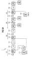
- FIG. 5 shows a particularly advantageous embodiment of an amplifier according to the invention.
- FIG. 5 shows an arrangement of optical elements of a unidirectional branch 10, 20 between the two circulators 31, 32 of a bidirectional path section 30.
- the arrangement contains 5 amplifiers 110-140, 160, all of which are erbium-doped fiber pieces 111-141, 161 contain.
- a WDM coupler 113-143 is provided; only the amplifier 161 has two WDM couplers 1631, 1632.
- the first two amplifiers 110, 120 are supplied by a pump source 112 in the 980 nm range via a power divider 116.
- the amplifier 130 is supplied by a pump laser 132 in the 1480 nm range, while the amplifier 140 is pumped by a pump laser 142 in the 980 nm range.
- the amplifier 160 is pumped contradictionally by 3 lasers 1621-1623 in the 1480 nm range, the pump sources 1621-1623 being arranged once in front of the optically active fiber piece 161 and the other time behind the optically active fiber piece 161. Lasers 1622 and 1623 can preferably be operated in multi-plexed fashion.
- an isolator 191 and a band pass filter 151 are attached.
- the second amplifier 120 is followed by a gain flattening filter 170, which in turn is from a tab coupler arrangement (180), which contains a variable optical attenuator 185, is followed.
- This coupler arrangement 180 follows Amplifier 130. After the amplifier 130 is a dispersion compensating Fibre 101 attached by two Isolators 192, 193 and various coupling elements 181, 182 is framed. Then the amplifier arrangement in turn an amplifier 140 followed by a band pass filter 152 becomes. After the bandpass filter is another amplifier stage 160 provided, which is completed by the coupling element 183 becomes.
- the function of the input stage according to the invention has already been described by Figure 4.
- the gain flattening filter 170 now has the task of the first two amplifier stages Level 110, 120 winning spectrum.
- the variable optical Attenuator 185 serves to compensate for the dynamic profit tilt.
- dispersion-compensating follows Fiber piece 101.
- a dispersion compensating Fiber piece 101 is preferably an add-drop multiplexer used, which compensates for the dispersion and through which individual channels are fed into and out of the fiber the fiber can be coupled out.
- the use of the dispersion compensating Fiber piece is very particularly preferred at the point of use of the amplifier according to the invention, since the optical signal is already sufficiently amplified here is and nonlinear effects, such as those through a full gain occur, have not yet occurred.
- An amplifier is provided an arrangement which is a powerful, low noise amplification bidirectional optical signals allowed.
- the present invention relates to a low-noise bidirectional optical amplifier operating in a bidirectional Transmission fiber is arranged so that by means of two circulators the bidirectional transmission fiber into two unidirectional Branches is split.
- the unidirectional branches are equipped with at least two amplifiers, between which preferably have at least one optical filter element and preferably at least one insulator is arranged.
- the active fiber of the first amplifier of the unidirectional Branches preferably pumped through a WDM coupler that is placed after the active fiber.
Applications Claiming Priority (2)
| Application Number | Priority Date | Filing Date | Title |
|---|---|---|---|
| DE10004435 | 2000-02-02 | ||
| DE10004435A DE10004435A1 (de) | 2000-02-02 | 2000-02-02 | Rauscharmer bidirektionaler optischer Verstärker |
Publications (1)
| Publication Number | Publication Date |
|---|---|
| EP1130821A2 true EP1130821A2 (fr) | 2001-09-05 |
Family
ID=7629508
Family Applications (1)
| Application Number | Title | Priority Date | Filing Date |
|---|---|---|---|
| EP00128432A Withdrawn EP1130821A2 (fr) | 2000-02-02 | 2000-12-22 | Amplificateur optique bidirectionnel à faible bruit |
Country Status (3)
| Country | Link |
|---|---|
| US (1) | US20010019449A1 (fr) |
| EP (1) | EP1130821A2 (fr) |
| DE (1) | DE10004435A1 (fr) |
Families Citing this family (25)
| Publication number | Priority date | Publication date | Assignee | Title |
|---|---|---|---|---|
| KR100342427B1 (ko) * | 2000-08-14 | 2002-07-02 | 윤덕용 | 다단 양방향 광증폭기 |
| DE10039950C2 (de) * | 2000-08-16 | 2002-09-05 | Siemens Ag | Bidirektionaler optischer Verstärker |
| AUPR316901A0 (en) * | 2001-02-16 | 2001-03-15 | Future Fibre Technologies Pty Ltd | Optic communication system |
| US6392790B1 (en) * | 2001-04-04 | 2002-05-21 | Redfern Broadband Networks Inc. | Bi-directional amplifier |
| US6819481B2 (en) * | 2001-06-04 | 2004-11-16 | Lucent Technologies Inc. | Bidirectional wave division multiplex systems |
| WO2005112308A1 (fr) * | 2004-04-08 | 2005-11-24 | Cybertron Co., Ltd. | Systeme de reseau optique passif a multiplexage par repartition en longueur d'onde |
| EP1788731B1 (fr) * | 2005-11-21 | 2011-06-22 | Alcatel Lucent | Système de transmission optique et ensemble filtre optique pour applications sous-marines |
| WO2009056365A1 (fr) * | 2007-10-29 | 2009-05-07 | Telefonaktiebolaget Lm Ericsson (Publ) | Améliorations dans ou relatives à des réseaux optiques |
| KR101143852B1 (ko) * | 2009-09-23 | 2012-05-22 | 신경민 | 고주파 열치료용 rf 제너레이터의 동상 모드 노이즈 필터 |
| EP2333991B1 (fr) * | 2009-12-11 | 2014-02-19 | Alcatel Lucent | Amplificateur optique bidirectionnel |
| CN102237932B (zh) * | 2010-04-30 | 2016-07-06 | 中兴通讯股份有限公司 | 长距光放大装置、无源光网络和光信号传输方法 |
| US20170272197A1 (en) * | 2016-03-17 | 2017-09-21 | Telekom Malaysia Berhad | Extender For Optical Access Communication Network |
| US10205552B2 (en) | 2017-01-20 | 2019-02-12 | Cox Communications, Inc. | Optical communications module link, systems, and methods |
| US10516922B2 (en) | 2017-01-20 | 2019-12-24 | Cox Communications, Inc. | Coherent gigabit ethernet and passive optical network coexistence in optical communications module link extender related systems and methods |
| US11502770B2 (en) | 2017-01-20 | 2022-11-15 | Cox Communications, Inc. | Optical communications module link extender, and related systems and methods |
| PL428292A1 (pl) * | 2018-12-20 | 2020-06-29 | Dawis It Spółka Z Ograniczoną Odpowiedzialnością | Sposób oraz system transmisyjny do ulepszonej jednokierunkowej lub dwukierunkowej transmisji danych w sieci telekomunikacyjnej, układ atraktora polaryzacji, program komputerowy oraz produkt w postaci programu komputerowego |
| US10993003B2 (en) | 2019-02-05 | 2021-04-27 | Cox Communications, Inc. | Forty channel optical communications module link extender related systems and methods |
| US10999658B2 (en) | 2019-09-12 | 2021-05-04 | Cox Communications, Inc. | Optical communications module link extender backhaul systems and methods |
| US11317177B2 (en) | 2020-03-10 | 2022-04-26 | Cox Communications, Inc. | Optical communications module link extender, and related systems and methods |
| EP3930228A1 (fr) * | 2020-06-26 | 2021-12-29 | ADVA Optical Networking SE | Procédé et appareil pour la gestion d'une capacité spectrale d'un système de multiplexage en longueur d'onde |
| US11146350B1 (en) | 2020-11-17 | 2021-10-12 | Cox Communications, Inc. | C and L band optical communications module link extender, and related systems and methods |
| US11271670B1 (en) | 2020-11-17 | 2022-03-08 | Cox Communications, Inc. | C and L band optical communications module link extender, and related systems and methods |
| US11323788B1 (en) | 2021-02-12 | 2022-05-03 | Cox Communications, Inc. | Amplification module |
| US11689287B2 (en) | 2021-02-12 | 2023-06-27 | Cox Communications, Inc. | Optical communications module link extender including ethernet and PON amplification |
| US11523193B2 (en) | 2021-02-12 | 2022-12-06 | Cox Communications, Inc. | Optical communications module link extender including ethernet and PON amplification |
Family Cites Families (3)
| Publication number | Priority date | Publication date | Assignee | Title |
|---|---|---|---|---|
| JPH08265258A (ja) * | 1995-03-20 | 1996-10-11 | Fujitsu Ltd | 光増幅中継器 |
| JPH0993202A (ja) * | 1995-09-21 | 1997-04-04 | Fujitsu Ltd | 双方向光増幅回路 |
| IT1283373B1 (it) * | 1996-07-31 | 1998-04-17 | Pirelli Cavi S P A Ora Pirelli | Sistema di telecomunicazione ottica multicanale bidirezionale |
-
2000
- 2000-02-02 DE DE10004435A patent/DE10004435A1/de not_active Withdrawn
- 2000-12-22 EP EP00128432A patent/EP1130821A2/fr not_active Withdrawn
-
2001
- 2001-02-01 US US09/775,269 patent/US20010019449A1/en active Pending
Also Published As
| Publication number | Publication date |
|---|---|
| DE10004435A1 (de) | 2001-08-30 |
| US20010019449A1 (en) | 2001-09-06 |
Similar Documents
| Publication | Publication Date | Title |
|---|---|---|
| EP1130821A2 (fr) | Amplificateur optique bidirectionnel à faible bruit | |
| DE60116101T2 (de) | Kaskadiertes pumpsystem zur verteilten ramanverstärkung in faseroptischen übertragungssystemen | |
| EP0613221B1 (fr) | Amplificateur à fibre optique à étages multiples | |
| DE69633476T2 (de) | Faseroptischer Verstärker und dispersionskompensierendes Fasermodul für faseroptischen Verstärker | |
| DE60213494T2 (de) | Bidirektionales optisches Verstärkermodul | |
| DE60031141T2 (de) | Lichtverstärker unter verwendung der ramanverstärkung und zugehöriges steuerungsverfahren | |
| DE60109024T2 (de) | Verbesserter breitbandiger Erbium-dotierter Faserverstärker (EDFA) | |
| DE69737117T2 (de) | Unterdrückung von Übersprechen in einem optischen Mehrwegverstärker | |
| DE19516439A1 (de) | Optischer Verstärker sowie Empfänger und optisches Übertragungssystem mit einem solchen | |
| DE19704685A1 (de) | Optischer Verstärker | |
| EP0579023B1 (fr) | Système de transmission d'informations optiques avec filtre optique pour protéger contres les très grandes impulsions | |
| DE10057659B4 (de) | Optisches Übertragungssystem mit jeweils mehrere Pumpquellen aufweisenden kaskadierte Raman-Verstärkern | |
| DE602004002204T2 (de) | Zählergepumpte verteilte raman-verstärkung in optischen kommunikationssystemen mit wellenlängenmultiplex | |
| DE10112806C1 (de) | Pumpquelle mit erhöhter Pumpleistung zur optischen breitbandigen Raman-Verstärkung | |
| DE60126531T2 (de) | Codotierter optischer Hochleistungsverstärker mit MEHREREN ABGRIFFEN | |
| EP1180859B1 (fr) | Amplificateur optique bidirectionnel | |
| DE60209841T2 (de) | Dispersionskompensierter optischer Faserverstärker | |
| EP0766358B1 (fr) | Amplificateur à fibre optique pour une multitude de signaux à longueurs d'onde différentes comprenant un démultiplexeur et un multiplexeur | |
| EP0766357B1 (fr) | Amplificateur à fibre optique pour une multitude de signaux à longueurs d'onde différents comprenant un filtre Fabry-Perot | |
| DE69829330T2 (de) | Zuverlässigkeitsverbesserung eines optischen Übertragungssystems und Verfahren geeignet dafür | |
| DE69929645T2 (de) | Optischer Verstärker, Übertragungsgerät, Übertragungssystem und Verfahren | |
| DE10048460B4 (de) | Raman-Verstärker | |
| DE19838602B4 (de) | Verstärker für optische Impulse | |
| DE602004006298T2 (de) | Optisches netzwerk und verstärkerknoten dafür | |
| DE60012826T2 (de) | Multiband-Ramanverstärker |
Legal Events
| Date | Code | Title | Description |
|---|---|---|---|
| PUAI | Public reference made under article 153(3) epc to a published international application that has entered the european phase |
Free format text: ORIGINAL CODE: 0009012 |
|
| AK | Designated contracting states |
Kind code of ref document: A2 Designated state(s): AT BE CH CY DE DK ES FI FR GB GR IE IT LI LU MC NL PT SE TR |
|
| AX | Request for extension of the european patent |
Free format text: AL;LT;LV;MK;RO;SI |
|
| STAA | Information on the status of an ep patent application or granted ep patent |
Free format text: STATUS: THE APPLICATION IS DEEMED TO BE WITHDRAWN |
|
| 18D | Application deemed to be withdrawn |
Effective date: 20030701 |